Shoeleh Vahdatpour | Afrooz Rahimi Ariaei*
© 2020 IIETA. This article is published by IIETA and is licensed under the CC BY 4.0 license (http://creativecommons.org/licenses/by/4.0/).
OPEN ACCESS
Four-sided wind catchers are common examples of wind catchers in Yazd. Analysing the physical and structural features of these wind catchers can reveal part of the characteristics of traditional Iranian architecture and the ability of traditional architects to use such renewable energies as wind power. The present study attempts to examine the effect of the arrangement of main and accessory air-shaft partition walls on the structural behaviour and construction technology of four-sided wind catchers through conducting library and field research studies. The study also attempts to simulate the process of constructing a four-sided wind catcher based on an optimal type. The analyses indicate that in addition to the amount of air conditioning, the shape of the partition walls has a direct relationship with the wind catcher’s degree of resistance to the internal and external forces. Moreover, the extension of the partition walls into the entirety of the rack and canal, compared to other similar types with partition walls in the rack, are more resistant against the lateral forces and transfer their resultant pressure more consistently thanks to their connected and consistent structure. The analysis of the construction process of wind catchers revealed part of the characteristics of the traditional Iranian architecture, utilizing vernacular materials and aiming at constructing high structures that are efficient, resistant, and dependent on renewable wind energy.
construction technology, four-sided wind catchers, main air-shaft partition walls, wind catcher’s structural behaviour, Yazd, Iran
Wind catchers have long been known as architectural strategies to control climate conditions in warm-dry and warm-humid areas in some parts of the Middle East and North Africa. The main function of wind catchers lies in the natural cooling of buildings’ internal environment through setting airflow in motion and evaporative cooling. Wind catchers can be seen in different forms in various geographical areas. Such differentiation in type and form depends on several factors, including the prevailing type of wind, wind direction and velocity, the presence of disturbing winds and tornadoes in the area, local temperature, maximum variation of day and night temperature, intensity of solar radiation, the importance of the space used, and master builders’ idiosyncratic methods [1-3]. The main function of the wind catcher as a passive system in the use of renewable wind energy is the natural cooling of the interior environment of the building through setting air flow by creating air flow or exploitation approach of the pressure difference between the inlet and outlet points of the wind, It guides inside the building if the wind blows, and if not, it helps the ventilation process of the building by letting the air out (like a chimney). In hot and dry areas (low humidity) by passing wind through the wet surface (ponds) cooling capacity of the wind catcher (evaporative cooling) is increased. Due to the optimal efficiency, ease of construction with eco-friendly materials in each area, wind deflectors have been used in various buildings (public and private) and can be seen in different physical forms.Yazd is one of the desert cities in Iran with a warm-dry climate, where architects have long employed several strategies like using wind catchers to control its climatic conditions. Today, wind catchers have lost their main function; they only serve an identity symbol for the city and are considered ornamental elements owing to changes in lifestyle and spatial needs and the use of water air-conditioners in buildings [4]. However, studying and analysing different typologies of wind catchers from the perspective of architecture technology can reveal part of the geometry knowledge and lost construction techniques previously used by architects, and help the restoration of historical buildings, some parts of which have been ruined. Besides, in the design process of contemporary architecture and with the use of renewable energies, such an analysis can present appropriate patterns that comply with climate and the context of design. Accordingly, the present study aims at investigating some of the arrangement characteristics of air-shaft partition walls on the structural behaviour and construction technology of four-sided wind catchers in Yazd by addressing the following questions:
1. Do the various arrangement shapes of the middle partition walls have any effect on the wind catcher’s structural behaviour?
2. What impact does the way that the four-sided wind catchers’ main and secondary partition walls are arranged (either in the rack or in their entirety) have on their structural behaviour?
3. How are the construction technology and arrangement of materials in the four-sided wind catchers of Yazd?
The architecture of wind catchers has drawn the attention of many researchers. Some researchers have examined wind catchers in the Middle East and categorized them in terms of climate conditions. Others have categorized Iranian wind catchers according to their function, local names, number of floors, and/or number of sides receiving airflow [5-7]. In another categorization, researchers have paid attention to Iranian wind catchers in a specific geographical area like Yazd. They have categorized and studied the wind catchers in this city in terms of their location in the house, the shape of the plan, elevation, and section [8, 9] (Table 1). A consideration of the cooling function of wind catchers in buildings influenced by the shape of the wind catchers’ plan and the direction of open apertures in various areas and climates, an examination of the approaches to use wind catchers in modern buildings, and an investigation of the role of wind catchers in the reduction of energy consumption have constituted other lines of research. According to these studies, increased cooling power and optimum efficiency are considered as important principles in the use of both two-sided and four-sided wind catchers. As with the wind catcher in Yazd, this is a governing principle, all through the four seasons. However, this principle is only at work during the summer in the case of the wind catcher in Kerman [10]. Other studies, moreover, have considered the use of wind catchers in modern buildings in Yazd (instead of wet air coolers) and its performance improvement through such approaches as the application of wetted curtains hung in the wind catcher canal or wetted evaporative cooling pads installed at its entrance and its role in decreasing energy consumption [11]. Considering the height of wind catchers and the direction and speed of the wind, other researchers have also examined the construction technology of wind catchers and their seismic behaviour. According to them, direction, speed of the wind, and the height of the wind catcher are effective in its mass flow. The increased speed of wind decreases the temperature and increases the mass flow; however, the increased height of wind catchers decreases mass flow. The studies also indicate that wind catchers are vulnerable to earthquake shaking and wind catchers of higher height bear more damage compared to those of lower height [12]. Therefore, researchers have chiefly paid attention to typology and the general construction method of wind catchers, their cooling function, and seismic behaviour; however, the role of the components of wind catchers in their general structure has not been investigated. Since the arrangement of air-shaft partition walls influences the construction technology and structural behaviour of four-sided wind catchers, the present study has attempted to identify the structural features of four-sided wind catchers in Yazd for the first time.
The data of the present study were collected through library and field research studies, on the one hand, and calculation method, on the other, in order to investigate part of the structural features of Iranian wind catchers. In this study, different types of wind catchers in Yazd were first simulated (Appendix1) according to their physical characteristics, the number of sides receiving airflow, and the shape of the plan. Among them, four-sided wind catchers with a rectangular plan were selected as the most functional types. Because of the existing variation in the shape (plan and elevation) of wind catchers in this city, in the process of structural behaviour analysis and construction technology modelling of wind catchers, the samples under examination were selected from one floor, four-sided wind catchers with a rectangular plan and flat roof (Appendix2), which, in terms of function, are used at public level (traditional houses) in Yazd (Figure 1, 2 and Appendix3).
Table 1. Typology of wind catchers (Adapted from: [6-8, 13, 14] & Redrawing by Authors, 2019)
|
Geographical area |
The ground of typology |
Types |
|||||
|
Middle East |
Climate: |
Warm-dry (Dry areas of Iran, Iraq & Egypt) |
Warm-humid (Persian Gulf & Pakistan) |
Semi warm-dry (Afghanistan) |
|||
|
Iran |
Functional |
Functional |
Symbolic |
Functional-symbolic |
|||
|
Local name |
Ardekani |
Kermani |
Yazdi |
||||
|
Number of floors |
One floor |
Two floors |
|||||
|
Number of sides receiving airflow |
Two-sided |
Four-sided |
Six-sided |
Eight-sided |
|||
|
Yazd |
Shape of the plan |
Shaft |
Square |
Rectangle |
Long rectangle |
Hexagonal |
Octagonal |
|
Main shaft partition walls |
Diagonal (X shaped) |
Perpendicular (+ or H shaped) |
Combined (K shaped) |
||||
|
Elevation |
Open aperture |
Square |
Horizontal rectangle |
Vertical rectangle |
|||
|
Height |
Long |
Average |
Short |
||||
|
Roof |
Flat |
Inclined |
Curve |
||||
|
Section: |
Simple wind catcher without a dome not supplying air to the basement |
wind catcher with a dome supplying fresh air to two floors (ground floor and basement) |
wind catcher with a dome supplying fresh air to the ground floor |
||||
|
Location of wind catcher in the house |
Wind catcher being located behind the rectangular hall and along its axis |
Wind catcher being located in one of the corners of the northern hall |
Wind catcher being located in the corner of the yard |
||||
In the process of three-dimensionalization of all samples, in order to compare the effect of the shape of the middle partition arrangement on the performance of the wind catcher, in two modes of middle partition walls (1-extension of partitions in the rack and canal, 2- the partitions only in the rack), first the dimensions of the samples (length, Width, height, wall thickness) were considered similar and fixed, and only the arrangement of the middle partitions was drawn based on the available samples using AutoCAD 2017 software (at this stage, the intervening variables were considered fixed so that the desired variables could be reviewed and compared). Then, in the computational process, basic information such as volume, moment of inertia, and centre of gravity were obtained from the computational section of AutoCAD 2017 software in the path: Tools → Inquiry → Region/Mass Properties → Select objects. In the next step, the data were completed by applying coefficients and equations related to each section, so that the effect of variables could be examined and the performance of the samples could be compared.
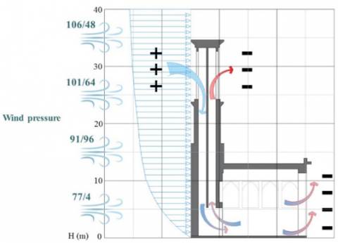
Yazd has a warm-dry climate and is located in a desert area in Iran; however, the city is not affected by sand winds thanks to the surrounding mountains. Therefore, to make the most of wind energy in the area, over 90 per cent of its wind catchers have been built in a four-sided shape. Wind catchers in Yazd are of higher height compared to other warm-dry areas in Iran. On average, their height is approximately 5 meters. The main elevation (plan elongation) in these wind catchers is mostly extended toward the north-west (Yazd’s optimum wind) (Appendix4) [9, 12, 15]. Wind stagnation pressure (q) in Yazd is equal to 60.5 daN/m2. In Figure 3, wind pressure at various levels on wind catchers in Yazd is shown.
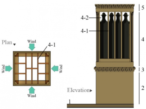
In four-sided wind catchers, air inlets are divided into four main shafts by some partition walls. Regardless of the wind direction, the wind is directed inside by one of these shafts. Made of either clay or brick, these shafts are divided into two types of main and accessory. Main partition walls serve a functional role in splitting wind catchers’ shafts and extended to the centre. Accessory partition walls, however, serve not only a decorative function on the façade of wind catchers, but also an accelerating one, increasing the speed of airflow in shafts (Bernoulli’s effect) (Appendix5). These partition walls are sometimes extended to the centre and sometimes lead only to the main shafts and choose this to build is happen under the circumstance of environmental conditions, dimensions and spatial needs and skill of craftsmen [13] (Figure 1).
1. The ground floor’s roof 2. Shaft 3. Zeh and zanjir
(A kind of brickwork with chain-like corrugated façade) 4. Wind catcher’s rack
4.1. Main and accessory partition walls 4.2. Decorative arches on partition walls 5. Wind catcher’s roof
Figure 1. Physical components of wind catchers
Figure 2. Typology of partition walls’ arrangement in four-sided wind catchers (Adapted from [8] & Redrawing by Authors, 2019)
Figure 3. Wind pressure at various height levels in Yazd (Appendix7)
In the process of modelling the samples in this study, the geometry of highly frequent secondary partition walls in Yazd has been used (Based on library and field studies). In what follows, the structural features of the sample types have been investigated (Tables 2-4). They have then been compared and contrasted so as to identify the optimal type. In the final stage, the construction method of a sample four-sided wind catcher has been simulated using traditional materials (Appendix6) (corresponding to the geometry of the optimal partition wall) and doing library research and field study (observations and interviews with traditional master builders).
The simulated sample that has undergone the process of structural analysis and final wind catcher construction modelling in this study is a one-floor four-sided wind catcher with a flat roof (with no supplying air to the basement). The area of the rectangular-shaped wind catcher also equals 2.00*1.70 m, its thickness equals 1.5 bricks of 0.3 m, and its height has been estimated to be 5.75 m2. The plan, moreover, is extended toward the north-west (Yazd’ optimum wind) (Figure 4). The final modelling process of wind catchers’ construction technology has been completed in four stages of calculating the specific volume and weight, calculating the moment of inertia and centre of gravity, selecting the optimal type of partition walls, and modelling the construction process.
Figure 4. Physical characteristics of the simulated wind catcher
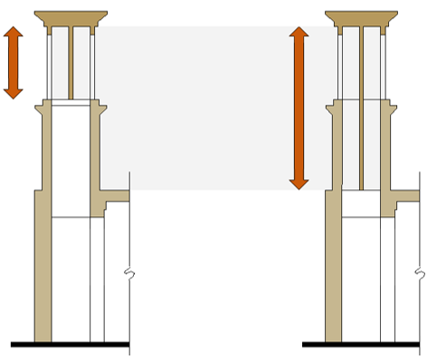
Since middle partition walls in four-sided wind catchers are sometimes in the rack only and in other cases, entirely extend to the bottom of the body, these two positions were also compared alongside the analysis of the samples’ plan (Figure 5). In what follows, samples with partition walls in the rack are indicated by P1 to P8 and those that are entirely extended to the bottom are shown by Ps1 to Ps 8.
Figure 5. The extension of the wind catcher’s main and secondary partition walls in the section
4.1 Calculating the specific volume and weight
In the analysis done, the specific weight of traditional materials has been considered 1700 kg/m3 Therefore, the specific weight γ)) equals to 16660 N/m3 [16]. Since the materials are assumed similar (brick and mortar, excluding plaster coating) according to Eqns. (1) and (2), the specific weight and the acceleration resulted from gravity (g) are stable at the Earth’s surface. Density is defined in terms of the kilogram per cubic meter (ƿ); therefore, it can be concluded that the higher the weight (w) is, the higher the mass (m) will be (Eqns. (3-5)).
W= m×g (1)
m= ƿ×v (2)
γ= ƿ×g (3)
W= v×ƿ×g (4)
W=v×γ (5)
Equations obtained from volume [17].
According to the analyses conducted, sample types Ps4 and P4 have the highest amount of specific volume, mass, and weight, respectively. Sample types Ps2 and P2 are considered in second place and samples Ps5 and P5 are in third place; however, samples Ps1 and P1 and then Ps8 and P8 have the lowest amount of specific volume, mass, and weight among the sample types (Table 2). One of the important factors in the design of a sustainable structure against the earthquake is its mass in a way that the building undergoes greater force as its mass and the intensity of the earthquake increase. Therefore, in samples of greater mass, such measures as the use of wooden struts to better transfer the forces have taken into account. Since these wind catchers have remained after so many years, it can be concluded that the tension caused by the pressure of mass on the wind catchers are less than the one caused by the sturdiness of the building materials. The analyses show that the number of materials used in the samples with partition walls in their entirety increases between 0.14 and 0.23 per cent compared to those with partition walls in the rack. According to the calculations done, the type of the partition wall and its height have a significant impact on the wind catcher’s weight. In fact, the choice of the partition wall can increase the weight by 2623.95 N (Table 2).
4.2 Calculating the moment of inertia and the centre of gravity
Corresponding to the principles of the article 3-9 of the Iranian Standard No. 2800, to strengthen a high structure against earthquake forces, a system that is resistant to the lateral load should transfer the force from an upper level to a lower one. Creating a continuous and consistent structure, especially in wind catchers with partition walls in their entirety (Ps1-Ps8), has made it possible to more consistently transfer the pressure caused by the forces. Moreover, based on the national rules of the building, the sixth chapter, articles 1-5-1-7-6, the plan of the structure should be, to the extent possible, simple and symmetrical along two sides, perpendicular, and without much projection and recess. Attempts should also be made to avoid making asymmetrical changes of plan in the height of the building as much as possible. This can be seen in the plan and elevation of the samples under investigation. Therefore, in the construction of high structures, the traditional Iranian architects have considered building principles and enforced forces based on experience and skill in applying the practical knowledge of geometry. In what follows, two influential topics in the resistance of the wind catcher structure (moment of inertia and centre of gravity) in the samples have been investigated.
Table 2. Calculation of the specific volume and weight
|
Samples with partition walls in the rack |
Samples with partition walls in their entirety |
||||
|
Type’s name |
Volume |
W |
Type’s name |
Volume |
W |
|
P 1 |
6.9263 |
115,392.158 |
Ps 1 |
7.9401 |
132,282.066 ò |
|
P 2 |
7.6216 |
126,975.856 |
Ps 2 |
9.2687 |
154,416.542 ñ |
|
P 3 |
7.2669 |
121,066.554 |
Ps 3 |
8.5910 |
143,126.06 |
|
P 4 |
7.7826 |
129,658.116 |
Ps 4 |
9.5763 |
159,541.158 ñ |
|
P 5 |
7.5482 |
125,753.012 |
Ps 5 |
9.1987 |
153,250.342 ñ |
|
P 6 |
7.3912 |
123,137.392 |
Ps 6 |
8.8285 |
147,082.81 |
|
P 7 |
7.2174 |
120,241.884 |
Ps 7 |
8.4964 |
141,550.024 |
|
P 8 |
7.1622 |
119,322.252 |
Ps 8 |
8.3909 |
139,792.394 ò |
Table 3. Moments of inertia and centre of gravity
|
Type’s name |
Moments of Inertia |
Radii of Gyration |
||||
|
X |
Y |
Z |
X |
Y |
Z |
|
|
P 1 |
65.8544 |
68.5978 |
17.3865 |
3.0835 |
3.1471 |
1.5844 ñ |
|
Ps 1 |
69.0450 |
72.2061 |
19.7903 |
2.9488 |
3.0156 |
1.5787 ñ |
|
P 2 |
77.8474 |
80.6936 |
18.8690 |
3.1959 |
3.2538 |
1.5734 ò |
|
Ps 2 |
83.0388 |
86.3963 |
22.6229 |
2.9932 |
3.0531 |
1.5623 ò |
|
P 3 |
71.7466 |
74.5186 |
18.1240 |
3.1421 |
3.2023 |
1.5793 |
|
Ps 3 |
75.9325 |
79.1481 |
21.1994 |
2.9730 |
3.0353 |
1.5709 |
|
P 4 |
80.5664 |
83.6185 |
19.2786 |
3.2175 |
3.2779 |
1.5739 ñ |
|
Ps 4 |
86.1685 |
89.9192 |
23.4056 |
2.9997 |
3.0643 |
1.5634 ñ |
|
P 5 |
76.5300 |
79.4922 |
18.7370 |
3.1842 |
3.2452 |
1.5755 |
|
Ps 5 |
83.5858 |
87.1923 |
22.5324 |
3.0144 |
3.0788 |
1.5651 |
|
P 6 |
73.8167 |
76.7944 |
18.4288 |
3.1602 |
3.2233 |
1.5790 |
|
Ps 6 |
78.2931 |
81.9017 |
21.7818 |
2.9780 |
3.0458 |
1.5707 |
|
P 7 |
70.9054 |
73.6939 |
18.0687 |
3.1344 |
3.1954 |
1.5822 ñ |
|
Ps 7 |
74.9608 |
78.2079 |
21.0937 |
2.9703 |
3.0339 |
1.5756 ñ |
|
P 8 |
69.8374 |
72.6184 |
17.7205 |
3.1226 |
3.1842 |
1.5730 ò |
|
Ps 8 |
73.6287 |
76.8615 |
20.4284 |
2.9622 |
3.0266 |
1.5603 ò |
Table 4. Classification of wind catchers with partition walls in their entirety
|
Gauge Classification according to optimal function |
Volume & W |
Moments of Inertia (Z axis) |
Radii of Gyration (Z axis) |
|
1 |
Ps4 |
Ps4 |
Ps8 |
|
2 |
Ps2 |
Ps2 |
Ps2 |
|
3 |
Ps5 |
Ps5 |
Ps4 |
|
4 |
Ps6 |
Ps6 |
Ps5 |
|
5 |
Ps3 |
Ps3 |
Ps6 |
|
6 |
Ps7 |
Ps7 |
Ps3 |
|
7 |
Ps8 |
Ps8 |
Ps7 |
|
8 |
Ps1 |
Ps1 |
Ps1 |
Figure 6. The construction process of four-sided wind catchers
Table 5. The construction process of four-sided wind catchers [18, 19] & Authors, 2019
|
Component part |
No. |
Name of elements |
Construction method |
|
Shaft |
D1 |
1-1. External walls |
- Constructing the walls of the wind catcher from the ground floor ceiling to the beginning of wind catcher’s open aperture with thickness proportional to the dimensions of wind catchers (approximately the size of one and a half or two brick lengths the dimensions of the door's brick are as follows: width: 20, length: 20, a thickness: 5 cm |
|
1-2. Horizontal struts |
-Use of horizontal wooden struts (corresponding to the arrangement shape of the wind catcher's partition walls) so as to hold the partition walls and transfer their load to the body of wind catcher -Horizontal struts aligned to the external body of the canal are constructed at various intervals depending on the height of wind catcher's canal. - Filling the gaps among horizontal wooden struts with either clay or brick. |
||
|
1-3. Main and subsidiary partition walls |
- Constructing the wind catcher's partition walls and the canal's wall with an approximate thickness of 5-8 cm at the same time and extending it to the roof (using horizontal struts) |
||
|
Zeh and zanjir |
D2 |
2.1- Wall, with a zanjir-lik facade |
- Constructing a number of rows using clay or brick in a distance between the shaft and the rack of the wind catcher with a chain-like façade, which is sometimes whitened with plaster. Forward (5 to 10cm) of each row relative to the bottom row |
|
2-2. Main and subsidiary partition walls |
- Extending the wind catcher's partition walls to the inner part) The extension of: D1/1-3). |
||
|
Rack |
D3
|
3-1. External walls |
- Constructing a number of rows of similar thickness to that of the body of the shaft up to the beginning of the rack. |
|
3-2. Main and subsidiary partition walls |
- Extending the wind catcher's partition walls to the inner part) The extension of: D1/1-3). - Horizontal wooden struts: for the most part, partition walls in this part of the building stand out and are more visible in relation to the outer body. At the time of execution when wood boards are placed on them, they are used as scaffolding. |
||
|
3-3. Vertical struts |
- Constructing vertical wooden struts in the junction of partition walls and body, which are extended to wind catcher’s ceiling - Today, angle bars and metal cans can be used as partition walls. |
||
|
3-4. Constructing walls and corner of wind catchers in a beveled or round shape facing inside |
- The adavantges of turning the wall in the corner of the wind catcher's rack circular or bevel-shaped: a. To increase the statics of the building against the slide of open apertures’ ceiling b. To cause the wind to circulate from the corners to the other side instead of striking a flat surface; this excludes the amount that is absorbed by the open apertures. |
||
|
3-5. Horizontal wooden strut on the walls in the corner of the wind catcher |
-Using wood in the horizontal strut on the walls in the corner of the wind catcher at certain intervals (about every 2 meters) with wood. |
||
|
Ceiling and roof’s covering |
D4 |
4-1. Constructing the roof |
- The stages of constructing the roof include: roofing plan, drainage, embankment, and brick flooring). - In wind catchers of larger dimensions on the surface of the roof, clay pots (i.e. soucheh) were installed. Rainwater is collected in these pots and is gradually evaporated |
|
4-2. Parapet |
- Constructing and decorating Parapet using clay or brick (in the shape of zeh or zanjir) and coating it with plaster on the façade. |
||
|
Coating and decorations |
D5 |
5-1. Decorative arcs on the facade |
- Constructing decorative arches (in various designs) on partition walls using clay or plaster coating. |
|
5-2. Thatching the internal and external walls of wind catcher |
- Thatching the internal and external walls of wind catcher with cob or glutinous straw (consisting of moving sand and cob) or simgel (consisting of sieved vivid clay and washed straw). |
||
|
5-3. Ornamental plasterwork on the elevation of the wind catcher's canal |
- Are built in various shapes on the basis of the architect's taste |
Moment of inertia is a quantity expressing a body’s tendency to resist rotation from the normal state around a rotational axis, and it can be considered as the main factor in bending resistance. Moment of inertia is very much related to the way mass is distributed in the section. The closer is mass to the centre, the lower is the moment of inertia. The level of tension and bending transformation of a component depends on the enforced force and the geometric shape of its section. The larger is a section’s moment of inertia, the lower is its tension level and bending transformations [17]. Therefore, the larger a body’s moment of inertia is, the higher its resistance against bending and rotation will be. According to the analyses done, sample types Ps4 and P4, and then the samples Ps2, P2, Ps5, and P5 have the largest amount of moment of inertia, respectively. Therefore, they are more inclined to maintain their previous state. However, samples Ps4 and P4, and then Ps2, P2, Ps5, and P5 have, respectively, the lowest amount of moment of inertia compared to the other sample types (Table 3). Therefore, one of the solutions that the traditional architects resorted to for the design of the bending components of wind catchers was increasing their moment of inertia so as to resist bending. Besides increasing ventilation, moreover, the internal network division of the wind catchers was attributed to an inclination to deflect neutral load and, consequently, increase the resistance of the section against bending. Since a decrease of mass in the height brings the structure’s centre of gravity closer to the ground level, and, consequently, reduces the possibility of collapse at the time of the earthquake, it can be stated that compared to the samples Ps1 to Ps8 (with partition walls in their entirety), the resistance of the wind catcher against the earthquake forces in the samples P1 to P8 (with partition walls in the rack) has reduced as the mass increases to higher levels. Therefore, one of the reasons for the frequency of wind catchers with partition walls in their entirety was attributed not only to greater suction potential but also to structure-related issues.
On the other hand, in physics, the centre of gravity of a set of particles is a particular point that, in many issues related to the system, behaves in a way as if all weight is concentrated at that point. The centre of gravity only depends on the location and weight of particles that form the system. In symmetrical shapes, the centre of mass is the centre of gravity [20]. The lower the centre of gravity of a structure is, the more stable it is against lateral forces, centre earthquake and wind powers. The analyses indicate that samples Ps8 and P8 with partition walls in a perpendicular position in the shape of “H” and samples Ps2, P2, Ps4, and P4 with partition walls in a perpendicular position in the shape of “+” has the lowest centre of gravity. Therefore, they are more resistant to lateral forces. In similar situations, the centre of gravity is the highest in the sample types Ps1 and P1, with diagonally arranged partition walls and samples Ps7 and P7 with partition walls in a perpendicular position in the plan. Overall, the shape of the middle partition walls has had no significant effect on the gravity level of wind catchers in Yazd. On the other hand, the analyses show that the samples with partition walls in their entirety (Ps) have lower gravity compared to those with partition walls in the rack (P), thus they are more resistant to lateral forces (Table 3).
4.3 Selecting the optimal type and modelling the construction process
Based on the analyses done, wind catchers with partition walls in their entirety are more resistant against bending, torsional, and lateral (wind and earthquake) forces. Therefore, at this stage, after a comparison of various wind catchers with partition walls in their entirety, the best samples were introduced according to their optimal function in the moment of inertia and centre of gravity. Among them, a four-sided wind catcher from the sample Ps2 (the optimum sample in both measures) was selected to simulate the construction process (Table 4). Overall, the construction stages of the wind catcher include constructing the external components (walls, ceiling, and ornaments) and internal components (partition walls and wooden struts) whose construction begins simultaneously and from the bottom-most part of the wind catcher (connecting external walls to the partition walls and structs) to create a consistent and resistant structure against the external and lateral forces. In what follows (Figure 6 and Table 5), the construction stages of each part of the wind catcher and their characteristics have been presented. It should be noted that besides the struts of the wind catcher’s partition walls, one of the common elements in the structure of wind catchers is the use of horizontal and vertical wooden struts in the external wall of its rack. The analysis of the simulated sample revealed that these structs increase the resistance of wind catchers against bending and torsional forces while they do not have a significant effect on wind catchers’ resistance against lateral forces (Table 6).
The analyses indicated that the choice of materials, design of the form, type of partition walls in the plan and section of the wind catcher is not only effective in its degree of ventilation, but also have a direct relationship with the resistance degree of the wind catcher’s structure against internal and lateral forces. The comparative study of the sample types shows that wind catchers with diagonally arranged partition walls need fewer building materials in terms of volume. However, their strength against lateral forces is lower compared to other types and are not that resistant to bending and torsional forces. Other types in a perpendicular position (+ shaped and H-shaped), the combined types (k shaped), and those partition walls of greater specific weight and splitting wind catchers’ main shaft into accessory shafts of smaller and approximately equal dimensions are more stable against bending and torsional forces in terms of function. However, although the samples with partition walls of perpendicular shape (H-shaped) are more resistant against lateral forces (wind and earthquake) compared to other samples, the shape of middle partition walls, in general, has had no significant impact on the degree of gravity in wind catchers in Yazd. Moreover, the analyses show that wind catchers with partition walls in their entirety—despite their higher specific weight compared to their counterpart samples with partition walls in the rack—convey the pressure caused by the forces in a more consistent fashion thanks to their continuous and consistent structure. Therefore, they are more resistant against the lateral forces compared to their counterpart samples with partition walls in the rack.
Table 6. Analysis of the structural features of the simulated wind catcher
|
Type of calculation |
Volume |
W |
Moments of Inertia |
Radius of Gyration |
||||
|
X |
Y |
Z |
X |
Y |
Z |
|||
|
Wind catcher with horizontal and vertical wooden strut on the external body of the rack |
8.82 |
146.94 |
89.48 |
92.77 |
21.62 |
3.18 |
3.24 |
1.56 |
|
Wind catcher without wooden struts on the external body of the rack |
8.80 |
146.60 |
89.06 |
92.33 |
21.56 |
3.18 |
3.23 |
1.56 |
New paragraph: The simulation of the construction technology of four-sided wind catchers in Yazd show that, in the past, depending on environmental contexts and spatial needs of buildings, Iranian architects, though unfamiliar with today’s structural calculations, constructed stable buildings having efficient shape and frame based on domestic materials by solely relying on their ancestors’ experiences and their own acquired knowledge (practical knowledge of geometry) (See Figure 6, & Table 5). The following strategies show that traditional architects have not only considered the function and aesthetic properties of buildings in constructing high-rise structures, but also the structural principles of construction and the enforced loads:
(1) Considering a simple and symmetrical shape in the plan of the structure and avoiding asymmetrical changes in the building’s plan and elevation;
(2) Employing partition walls in the entirety of structures (to increase its resistance against lateral forces through the consistent distribution of pressure caused by the forces);
(3) Taking into account the system of partition walls in wind catchers to increase the ventilation power and improve the structural function against bending, torsional, and lateral forces;
(4) Considering horizontal and vertical struts to increase the function of wind catchers against bending and torsional forces.
Although Iranian wind catchers have been classified by other researchers in terms of climate types, function, local name, number of floors, number of sides receiving airflow, and/or their features in various geographical areas and some of their architectural and functional characteristics have been analysed, the present study has investigated wind catchers in Yazd so as to shed light on some of the hidden concepts in their architecture and construction technology. On the one hand, the present study can be helpful in better recognizing the architectural and structural characteristics of wind catchers in Yazd and utilized in restoration designs buildings (maintenance and/or renovation) of and historical contexts, in such areas as physical (shape and form) and structural characteristics (materials, components, connections, and type of optimal partitioning) of wind catchers according to local knowledge and experiences. On the other hand, it can help propos new designs based on the exploitation approaches of renewable energies. These solutions can be updated and used in keeping with today’s technologies and new spatial requirements. Furthermore, the analytical approaches used in the present study can be applied to studies where other Iranian ancient structures and techniques such as khishkhān-ha (dome-like ventilator on the roof), windmills, and water-mills are to be investigated in the scope of other various cities.
|
g |
gravity (m/s2) |
|
m |
mass (kg) |
|
V |
volume (m3) |
|
W |
weight (kg. m/s2=N) |
|
Greek symbols |
|
|
γ |
specific weight (N /m3) |
|
ƿ |
Density (kg/ m3) |
(1) All drawings and calculations have been done by the authors using AutoCAD 2017 and Photoshop 2018.
(2) The shape of the roof in the majority of wind catchers in Iran, particularly those in Yazd, is flat [1].
(3) Typology of partition walls’ arrangement in wind catchers (Figure 7).
(4) The location of wind catchers, physical proportions, and the number and direction of open apertures are generally affected by the direction of the optimum wind, the location of the site, area, and the connecting space with the wind catcher. In Yazd, wind catchers are generally built on the south-western side of the houses as it receives the least amount of sunlight in warm seasons. Wind catchers of higher height are potentially more capable of directing wind, yet less resistant to earthquake forces [12, 19].
(5) According to Bernoulli’s effect, an increase in the speed of air airflow occurs when it passes through a tightened section [21].
(6) Traditional materials used to construct wind catchers are raw clay, plaster, Shūrūneh timber, which is a kind of hefty wood resistant to termite infestations [1].
(7) Wind pressure has been calculated using P=Ce.Cq.q. In this equation, P, Ce, Cq, and q are pressure of wind, gust factor coefficient, pressure coefficient, and wind stagnation pressure, respectively.
Figure 7. Typology of partition walls’ arrangement in wind catchers (Adapted from [22, 23] & Redrawing by Authors, 2019)
[1] Valibeigi, N., Nasekhian, S., Tavakoli, S. (2014). The role of wind catchers in improving people’s comfort. Eco-Architecture V: Harmonisation between Architecture and Nature, 142: 93-102. http://dx.doi.org/10.2495/ARC140091
[2] Pirhayati, M., Ainechi, S., Torkjazi, M., Ashrafi, E. (2013). Ancient Iran, the origin land of wind catcher in the world. Research Journal of Environmental and Earth Sciences, 5(8): 433-439. https://doi.org/10.19026/rjees.5.5671
[3] Afshin, M., Sohankar, A., Manshadi, M.D., Esfeh, M.K. (2016). An experimental study on the evaluation of natural ventilation performance of a two-sided wind-catcher for various wind angles. Renewable Energy, 85: 1068-1078. https://doi.org/10.1016/j.renene.2015.07.036
[4] Pourahmadi, M., Ayatollahi, S.M.H. (2012). Refunctioning solutions for different wind catchers of yazd based on their related summer side spaces. Scientific Journal Management System, 1(1): 7-18.
[5] Dehghan, A.A., Manshadi, M.D., Esfeh, M.K. (2014). Wind-catchers, creative buildings’ elements for passive ventilation. Advances in Energy Research and Development, 6: 189-222.
[6] Jomehzadeh, F., Nejat, P., Calautit, J.K., Yusof, M.B.M., Zaki, S.A., Hughes, B.R., Yazid, M.N.A.W.M. (2017). A review on windcatcher for passive cooling and natural ventilation in buildings, Part 1: Indoor air quality and thermal comfort assessment. Renewable and Sustainable Energy Reviews, 70: 736-756. http://dx.doi.org/10.1016/j.rser.2016.11.254
[7] Shariat Zādeh, A.A. (1995). Naqsh-e bādgir dar nāhiyeh-ye jonoubi-ye dasht-e kavir "ostān-e Yazd", in Proceedings of Iran’s Architecture History and Urbanization Congress, Ayatollah Zadeh Shirazi, B. (Ed.). Cultural Heritage Organization of Iran, Tehran, pp. 220-226.
[8] Bahadori Nejad, M. (2012). Bādgir, shāhkar-e mohandesi-ye Irān. Yazdā, Tehran. http://opac.nlai.ir/opac-prod/search/briefListSearch.do?command=FULL_VIEW&id=2726112&pageStatus=0&sortKeyValue1=sortkey_title&sortKeyValue2=sortkey_author, accessed on 10 October 2020.
[9] Mahmoudi, M. (2006). Wind catcher: An attractive and charming feature of Yazd city. The Monthly Scientific Journal of Bagh- E Nazar, 3(5): 91-99.
[10] Mahdavinejad, M.J., Javanrudi, K. (2011). Comparative evaluation of airflow in two kinds of Yazdi and Kermani wind-towers. Journal of Honar-Ha-Ye-Ziba: Memary va Shahrsazi, 3(4): 69-80. https://jfaup.ut.ac.ir/article_29678.html
[11] Bahadori, M.N., Mazidi, M., Dehghani, A.R. (2008). Experimental investigation of new designs of wind towers. Renewable Energy, 33(10): 2273-2281. http://dx.doi.org/10.1016/j.renene.2007.12.018
[12] Hejazi, B., Hejazi, M. (2014). Persian wind towers: Architecture, cooling performance and seismic behaviour. International Journal of Design & Nature and Ecodynamics, 9(1): 56-70. http://dx.doi.org/10.2495/DNE-V9-N1-56-70
[13] Aryan, A., Ehsan, Z., Amin, S., Masoud, K. (2010). Wind catchers: Remarkable example of Iranian sustainable architecture. Journal of Sustainable Development, 3(2): 89-97. http://dx.doi.org/10.5539/jsd.v3n2p89
[14] Zarandi, M.M. (2009). Analysis on Iranian wind catcher and its effect on natural ventilation as a solution towards sustainable architecture (Case Study: Yazd). World Academy of Science, Engineering and Technology, 54: 574-579.
[15] Mostafaeipour, A., Bardel, B., Mohammadi, K., Sedaghat, A., Dinpashoh, Y. (2014). Economic evaluation for cooling and ventilation of medicine storage warehouses utilizing wind catchers. Renewable and Sustainable Energy Reviews, 38: 12-19. http://dx.doi.org/10.1016/j.rser.2014.05.087
[16] Grigg, P. (2005). Westermann Mechanical Engineering Handbook. Amir Kabir Publications, Tehran.
[17] Valibeig, N., Rahravi Poodeh, S., Rahimi Ariaei, A. (2017). Structural and geometric analysis of discontinuous double-shell Persian domes in Isfahan and Nain dome-building schools. International Journal of Architectural Heritage, 11(8): 1101-1120. http://dx.doi.org/10.1080/15583058.2017.1325540
[18] Lorenz. R. (1999). Der Windturmbauer - Der Letzte seines Standes. Yazd, Iran. http://www.handwerksvideos.de/windturmbauer.htm, accessed on 10 October 2020.
[19] Golabchi, M., Javani Dizchi, A. (2013). Iranian Architecture Technology. University of Tehran, Tehran.
[20] Fowles, G.R., Cassiday, G.L. (2005). Analytical Mechanics. Thomson Brooks Cole, the UK.
[21] Pritchard, P.J., Mitchell, J.W. (2016). Fox and McDonald's Introduction to Fluid Mechanics. John Wiley & Sons, Holtsville, NY, USA.
[22] Ghadiri, M., Lukman, N. (2010). Wind Catcher, a Natural Evaporating Cooling system. 3rd International Graduate Conference on Engineering, Science and Humanities (IGCESH) School of Graduate Studies Universiti Teknologi Malaysia, pp. S1-S9.
[23] Ghadiri, M.H., Ibrahim, N.L.N., Mohamed, M.F. (2013). Performance evaluation of four-sided square wind catchers with different geometries by numerical method. Engineering Journal, 17(4): 9-18. http://dx.doi.org/10.4186/ej.2013.17.4.9