Bikheet Mohamed Sayed![]()
© 2025 The author. This article is published by IIETA and is licensed under the CC BY 4.0 license (http://creativecommons.org/licenses/by/4.0/).
OPEN ACCESS
Manual calibrators in mass measurement are widely common in mass technology. However, the process for calibration masses is monotonic and dangerous for heavy masses. This article concerns the main features of designing and controlling a low-cost, high-accuracy 2-axis automatic weight exchanger for mass measurement up to 20 kg with minimum requirements based on design constraint variables. The design variables are the mass and balance dimension, balance range, readability, weight of the masses, and the system's rigidity. Other key operational factors, including stability, motor sizing, and precise PID position control, should be considered and engineered for automated calibration. Lots of modifications are carried out to enhance the calibration process. The cost function generation is carried out to find the maximum number of masses that can calibrated according to the design variables. The weight exchanger has two 2-axis for motion in the Cartesian coordinate X-axis and Y-axis, respectively. The motors' size and speed are selected carefully to verify stability during the measuring process for each case. Experimental tests were conducted on four automatic weight exchangers for automatic mass calibration. Controlling the motion using PID position control for the automatic calibration based on the weight exchanger's maximum weight and the carried masses. The automatic system approves the mechanical design features and controls and performs measurements for masses up to 20 kg. The obtained results prove the feasibility of the proposed weight exchanger from design and control viewpoints. The results show that the automatic weight exchanger can efficiently calibrate 7, 4, 16, and 3 masses ranging from 50 g up to 20 kg based on design variables selection. Moreover, it enhances and reduces the standard deviations of the reading measurement compared to manual work.
standard mass, mass calibration, robotic system, weight exchanger, automatic calibration
Mass calibration is the process of determining the mass of an object by comparing a test weight to a reference mass standard that is a known and traceable value. This process is fundamental to science, industry, and trade, ensuring measurement consistency and accuracy. The primary instrument is a mass comparator, a high-resolution balance designed for differential weighing.
The traditional calibration process is performed manually according to specific weighing cycles, such as the R-T-R (Reference-Test-Reference) or R-T-T-R (Reference-Test-Test-Reference) schemes [1]. This manual process, however, has significant limitations. The presence of a human operator can introduce thermal disturbances (body heat), vibrations, and inconsistent weight handling, all of which increase measurement uncertainty [2]. High-precision calibration requires long thermal stabilization times and numerous repetitions for statistical validity, making it a very slow and costly process. Manual handling of high-purity mass standards (especially E1 and E2 class weights) with tweezers carries a risk of surface contamination or physical damage, altering their mass value [3]. The development of automatic mass carriers was driven by the need to overcome these limitations. By automating the loading and unloading of weights onto the mass comparator, these systems achieve higher throughput, improved repeatability, and a significant reduction in measurement uncertainty by isolating the measurement from human and environmental influences [4, 5].
Weight exchanger is used widely to calibrate standard masses ranging from 1 mg up to 500 kg. Peng et al. [6] introduce a combined feature of mass measurements in small nominal value, a data analysis and processing method based on the automatic measurement system.
Ota et al. [7] introduce a mass comparator's capability for accurately transporting and weighing sub-milligram weights. This research addresses the critical need for a sophisticated and robust data processing method specifically tailored for the output of automatic small-mass measurement systems. Solecki et al. [8] present a novel mass comparator to measure small weights of 2 mg and lower, with an unprecedented resolution of 10 ng readability. Moreover, this work presents a novel automatic mass comparator's design, development, and characterization. This instrument is specifically engineered for the high-precision calibration of mass standards with nominal values below 2 mg. Automatic weighing has recently been used to weigh masses in vacuum chambers to eliminate the air buoyancy effect between different masses [9].
However, the mass carriers in heavy masses are used widely, too. The basic design of the mass comparator improved calibration capabilities for large weights (100 kg to 500 kg) [10]. This novel design integrating a high-resolution Electro-Magnetic Force Compensation (EMFC) weighing cell with a robust, low-deformation mechanical structure and a fully automatic weight exchange mechanism was introduced. Moreover, the automated system ensures precise and repeatable loading of the test and reference masses, eliminating the errors and safety hazards associated with manual intervention.
A different series of serial robotic systems are used to calibrate standard masses from 1 mg up to 50 kg, and they are used in different robotic systems that can perform the task accurately and efficiently. Mettler Toledo: Their AX line of mass comparators is often equipped with integrated weight changers. For example, the AX1006 and AX505 comparators feature a turntable magazine that can hold up to 4 or 8 weights, respectively. The software MC Link manages the entire automated calibration process [11].
Sartorius (Minebea Intec): The CCE series of mass comparators is one of the industry-leading robotic systems. For instance, the Sartorius CCE manual series is a 50 kg capacity comparator with a 1mg resolution that uses a 2-position turntable for fully automatic [12]. RADWAG Known for high-quality mass standards. RADWAG also offers robotic calibration systems. Their systems often feature a carousel design and are designed to handle weights from 1 mg to 50 kg [13]. A multi-axis robotic arm picks up weights from a storage magazine and places them onto the weighing pan. This approach decouples the weight storage from the immediate vicinity of the weighing cell, potentially reducing thermal and vibrational interference. Those systems have initial and maintenance cost high.
Research into automated and high-precision mass determination has explored several advanced systems. Lee and Kwak [14] presented a 3-axis robot for automatically calibrating low-accuracy (class M) masses from 10 kg to 20 kg. The system was controlled by LabVIEW and produced results comparable to those of manual calibration. Ueki et al. [15, 16] designed an airtight chamber for standard masses from 1 kg to 20 kg to address environmental variables. By controlling internal pressure to keep air density constant, their system evaluates a weight's mass and volume simultaneously. In a more specialized application, McLinden et al. [17] described a hydrostatic comparator optimized for determining the density of sinkers used in magnetic suspension densimeters. Similarly focused on dual measurements, Sayed et al. and Hamdy et al. [18-20] designed a new apparatus to measure both mass and density from 1 kg to 20 kg, which included work on optimizing the balance pan and validating the system's performance.
National Metrology Institutes (NMIs): NMIs like NIST (USA), PTB (Germany), and METAS (Switzerland) have developed custom robotic systems. For example, the NIST-1 vacuum balance and the PTB's "Robot-Comparator-System" use robotic arms for the automated calibration of kilogram prototypes in a vacuum to minimize air buoyancy effects and surface contamination [21, 22]. These systems are not commercially available but represent the state-of-the-art in research. The BIPM (International Bureau of Weights and Measures) uses a custom-designed carousel-type automatic weight changer for its reference mass comparators, demonstrating the critical role of automation in maintaining the international mass scale [23].
Automatic calibration is one of the urgent requirements in mass meteorology because it has more accurate results than manual calibration. Moreover, the fully automated process allows efficient and highly accurate mass calibration. Furthermore, the absence of manual intervention during the automated process improves the quality and accuracy of the mass measurements. Additionally, manual calibration for standard masses has a monotonous sequence of calibration sequences. Finally, the maintenance of these systems is highly expensive.
This paper presents the design and control of a novel, low-cost mass carrier for calibrating standards from 50 g to 20 kg. The system's design is optimized based on balance capacity, readability, and mass dimensions. It features a 2-axis weight exchanger, actuated by two motors for horizontal and vertical motion, with torque and speed calculated to meet system requirements. PID controllers were designed to ensure stable operation, and a prototype demonstrated successful signal tracking with minimal steady-state error.
To validate the system, mass standards of E2, F1, F2, and M accuracy classes were calibrated automatically and compared against manual methods to determine measurement repeatability. The experimental work, conducted across four distinct test cases simulating different mass ranges and accuracy classes, confirmed the system's rigidity, motor performance, and controller effectiveness. The automated results showed strong agreement with manual calibrations, demonstrating the design's capability to accurately and efficiently calibrate a wide range of masses.
The mass is often calibrated according to OIML R111 recommendations. The sequence for mass is based on R-T-T-R and R-T-R. R refers to reference mass, while T refers to test mass.
Test mass calibration can be performed by comparing a standard mass with a known conventional mass ($m_{c r}$) and a test mass $\left(m_{c t}\right)$ [1]. The conventional mass can be measured using the following procedures: For cycles R-T-T-R and R-T-R. R. The conventional mass difference, ($\Delta m_c$), between a test and a reference mass (which have the same nominal values) of several cycles (i) is obtained by applying Eq. (1):
$\Delta m_c=m_{c t}-m_{c r}$ (1)
where,
$\left(m_{c t}\right)$ is the conventional mass of the test object and $\left(m_{c r}\right)$ is the conventional mass of the reference object.
The average difference in the conventional mass for n cycles is given by Eq. (2):
$\Delta m_{c i}=\Delta I_i-m_{c r} C_i$ (2)
where,
$\left(C_i\right)$ is the correction factor of the air buoyancy, $\left(\Delta I_i\right)$ is the indication difference between a test $(T)$ and a reference mass (R).
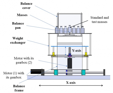
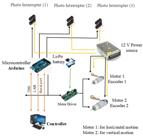
Automatic calibration is more reliable than manual work. Automating a non-automatic balance is crucial to increase capability and minimize the time required to calibrate masses. Figure 1 describes the main subsystems for automatic calibration. It is a balance's frame, balance pan, and weight exchanger (2-axis mechanism). The weight exchanger has two motors. Motor 1 is actuating the X-axis, while motor 2 is actuating the Y-axis. Some design considerations should be considered while designing the automatic weight exchanger. The first design consideration is the used balance capacity and its readability. According to these parameters, the user can know the maximum nominal mass that can be measured and its classes from E1 to M3. The maximum permissible error and the balance readability are also used to fix the mass's class. The second design consideration is the mass dimension, especially the outer diameter (D) as seen in Table 1.
Figure 1. Design consideration for weight exchanger (X-Y axis)
Table 1. The dimensions of OIML shape masses
|
Nominal Value, g |
Class |
Diameter, D, mm |
|
50 |
E2- M |
18 |
|
100 |
E2- M |
22 |
|
200 |
E2- M |
28 |
|
500 |
E2- M |
38 |
|
1,000 |
E2- M |
48 |
|
2,000 |
E2- M |
60 |
|
5,000 |
E2- M |
80 |
|
10,000 |
E2- M |
100 |
|
20,000 |
E2- M |
128 |
The user can measure the accepted class for the selected masses and the balance readability. Case 1, the balance maximum range is 320 g, its readability 0.1 mg, and its maximum permissible error, the user can measure masses with classes F1 to M. In cases 2 and 3, the user uses balance with maximum range 1,050 g and its readability.
0.01 mg, the user can calibrate mass from 50 g to 1,000 g with class E2 to M. Case 4, the user uses balance with maximum range 26.1 kg and its readability 1 mg, the user can calibrate mass from 5 kg to 20 kg with class E2 to M.
The design of each case can be calculated using the design parameters to determine the maximum number of masses that can be calibrated. However, the design parameters in the Y-axis to make the weight exchanger have consistent height with the balance frame's height. The main function of the motor 2 is loading or unloading masses. Then, the design based is applied for each axis according to the design considerations (constraints).
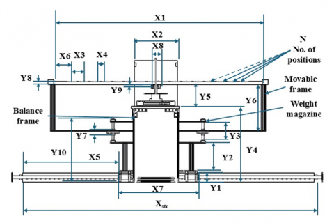
The design' parameters for each axis are shown in Figure 2. X-axis parameters design consideration is as follows.
Figure 2. Design consideration parameters for X-axis and Y-axis
Firstly, the maximum and minimum dimensions for standard and test masses (X3) are used to design the new balance pan. (X3) is equal to the maximum diameter of the mass (D) over the weight exchanger. Then, the balance width (X2) is required to design the width of the balance frame. Then, the no-mass distance (X6) can be calculated according to Eq. (3), which is equal to half of (X2) and a gap distance in the X-axis (a is a small distance which the designer can select).
$X 6=\frac{X 2}{2}+a$ (3)
To evaluate the length of the power screw in X-axis (Xstr), Eq. (4) and Eq. (5) are applied.
$X_{s t r}=2 X 5-X 7+a$ (4)
$X_{s t r}=X 1-X 2+a$ (5)
where,
(X5) is the half distance of the remaining distance of the X-axis, and (X7) is the distance between the two bearings.
Then, the user can calculate the maximum number of masses on the weight exchanger (N) using Eq. (6):
$X 1=2 X 6+(N-1)(X 3+X 4)$ (6)
where,
(X1) is the length of the mass holder, and (X4) is a small gab distance.
Finally, the design parameters for the X-axis are X1, X2, X3, X4, and a. The calculated parameters are X6, X7 and Xstr as seen in Table 2.
Table 2. Design parameters for X-axis and Y-axis
|
Balance Constraints |
||||
|
Design Parameters |
Case 1 up to 200 g |
Case 2 up to 1,000 g |
Case 3 up to 1,000 g |
Case 4 up to 20 kg |
|
Balance capacity, g |
320 |
1,050 |
1,050 |
26,100 |
|
Balance readability, mg |
0.1 |
0.01 |
0.01 |
1 |
|
Design Parameters for X-axis |
||||
|
X1, mm |
500 |
500 |
1,100 |
600 |
|
X2, mm |
250 |
250 |
250 |
300 |
|
X3, mm |
28 |
48 |
48 |
128 |
|
X4, mm |
10 |
20 |
5 |
5 |
|
a, mm |
10 |
20 |
5 |
15 |
|
Selected Parameters for X-axis |
||||
|
Xstr, mm |
250 |
250 |
800 |
300 |
|
X6, mm |
135 |
145 |
130 |
165 |
|
X7, mm |
260 |
270 |
530 |
315 |
|
N |
7.3 |
4.4 |
16.0 |
3.1 |
|
Design Parameters for Y-axis |
||||
|
Design parameters |
Option 1 up to 200 g |
Option 2 up to 1,000 g |
Option 3 up to 1,000 g |
Option 4 up to 20 kg |
|
Hal, mm |
30 |
30 |
30 |
30 |
|
TP, mm |
30 |
30 |
30 |
30 |
|
b, mm |
30 |
30 |
30 |
30 |
|
Y1, mm |
50 |
50 |
50 |
50 |
|
Y2, mm |
200 |
70 |
200 |
70 |
|
Y3, mm |
85 |
85 |
85 |
85 |
|
Y5, mm |
50 |
50 |
150 |
150 |
|
Y7, mm |
40 |
40 |
40 |
40 |
|
Y8, mm |
20 |
20 |
20 |
20 |
|
Y9, mm |
30 |
30 |
30 |
30 |
|
Selected Parameters for Y-axis |
||||
|
Ystr, mm |
25 |
25 |
25 |
25 |
|
Y4, mm |
440 |
310 |
440 |
310 |
|
Y6, mm |
185 |
185 |
385 |
285 |
|
Y10, mm |
350 |
220 |
350 |
220 |
According to the design parameters for the X-axis, Table 2 describes the effect of each parameter in selecting the number of masses that can be calibrated automatically. Eq. (3) to Eq. (6) are used to design the selected parameters. Four cases are applied to design the weight exchanger based on the design considerations.
Case 1, this design calibrates standard masses up to 200 g. The constraint parameter is the diameter of the standard masses (X3) according to the OIML 111 is 28 mm. X2 is 250 mm, and (X1) is 500 mm. By solving Eq. (6), the number of masses (N) can be estimated as 7.3. Therefore, N will be 7 masses.
Case 2, this design calibrates standard masses up to 1,000 g using the same previous design parameters (X1) and (X2). However, the diameter of 1,000 g is 48 mm. By solving Eq. (6), the number of masses (N) can be estimated as 4.1. Therefore, N will be 4 masses.
In case 3, the design parameters are the same as in the last case except that X1 is increased to 1,100 mm. Therefore, N will be 16 masses.
In the last case, the balance capacity is increased to be 26.1 kg, so this system can calibrate masses up to 20 kg. X3 for 20 kg is 128 mm. The balance width (X2) is 300 mm. X1 is 600 mm. Using Eq. (6), N is 3.1. Therefore, N will be 3 masses.
The design parameters for the Y-axis are selected to make the balance frame and the weight exchanger consistent.
Firstly, the design constraints are that the height of the weight exchanger (Y8) should be less than the height of the new balance pan (Y9) as in Eq. (7), the height of the vertical column (Y2), the height of the linear guide (Y2) and the height of the balance frame (Y5). According to the design parameters, Eq. (7) to Eq. (12) should be applied to get the selected parameters. Table 2 describes the design constraint parameters for four options. Option 1 and 3 are used motor coupling with power screw, so the column height (Y2) is 200 mm. However, options 2 and 4 use the coupling with a bevel gear. Therefore, the vertical column height is decreased to be 70 mm.
$Y 8<Y 9$ (7)
where,
(Y8) is the thickness of the balance, and (Y9) is the thickness of the balance pan.
The maximum stroke in Y-axis (Ystr) is equal to the height of linear guide (Y3) minus the height of the linear bearing (Y7) and 20 as Eq. (8):
$Y_{s t r}=Y 3-Y 7-20$ (8)
where,
20 is the height of two fixed coupling.
The height of the balance frame (Y4) is equal to the height of the weight exchanger movable frame for X-axis (Y1), the height of the vertical column to install motor 2 (Y2), the height of the linear guide in Y-axis (Y3) and a half distance of (b) as Eq. (9):
$Y 10=Y 1+Y 2+Y 3+0.5 b$ (9)
The height of the balance frame depends on the height of the weight exchanger (Y10), the height of the Aluminum profile of the balance frame (Hal), the thickness of the granite plate over the Aluminum profile (Tp) and a gab distance in Y-axis (b).
$Y 4=Y 10+H_{a l}+T_P+b$ (10)
Then, the movable frame height (Y6) can be calculated as Eq. (11).
$Y 6=0.5 Y 7+H_{a l}+T_P+b+Y 5$ (11)
where,
(Y5) is the distance between the balance and the mass holder, and the vertical distance between the bottom plate and the end of the fixed coupling.
Two positions are important for controlling the height of weight exchanger and the height of balance frame in Y-axis.
Eq. (12) is used to ensure the height of the balance frame is consistent with the weight exchanger height.
The first position is at no load on the balance pan. The linear bearing is at the higher position (Ystr is maximum). The condition for loading mass is as the given Eq. (12):
$Y 1+Y 2+Y_{s t r}+Y 6+Y 8>Y 4+Y 5+Y 9$ (12)
where,
(Ystr) is the vertical distance to load mass on the balance. However, the second position is while loading mass on the balance pan so the (Ystr) is less than the previous one.
For consistency, L.H.S. of Eq. (12) should be larger than R.H.S by a small distance. The L.H.S. for option 1 to 4, the height of the balance frame is 500, 370, 600 and 470 mm consequently. However, the height of the weight exchanger is 490, 360, 590 and 460 consequently.
These are the geometry parameters in X-axis and Y-axis. However, the maximum load should be considered for static and dynamic load. Furthermore, the motor size and its speed should be calculated. Moreover, the motor control the motion using a feedback position control.
The maximum stroke for two motions (horizontal or vertical) is minimized as much as possible according to the standard dimensions of masses to increase the number of masses that can be calibrated automatically (N). These factors fix the required system rigidity, the material of the weight exchanger. For small masses up to 200 g, the weight exchanger's plates can be manufactured with Aluminum alloy. For masses up to 1,000 g and increasing the number of masses, the exchanger's plates should be stronger than the previous status. For masses up to 20 kg, the weight exchanger should be designed with high thickness Aluminum plates to decrease the deflection or even using Steel alloy with high strength.
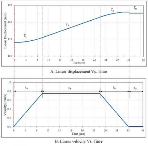
This application uses two brushed DC motors more frequently than others because they offer the highest precision in control positioning. The best actuator for the new multi-position series mass carrier requires a high-torque motor with a low speed. A planetary gearbox for the output motor shaft is a possible solution for increasing torque and reducing speed. It has a lightweight, small-volume solution with no backlash. Moreover, it can provide a coaxial input and output shaft, good resolution, and excellent repeatability. The trapezoidal curve is used to specify the motor's size, as obtained from Eq. (13) [24, 25] as shown in Figure 3. It depends on the torque required to raise the speed from zero to maximum speed (TA) and load torque (TL), the torque required to run at a fixed speed (TR), the torque required to decrease the speed from maximum speed to zero (TD), (TL) and standby torque Tss. tA is the time required for accelerated torque; tR is the time required for running; tss is the standby time and tD is the time required for decelerated torque. The motors are selected based on the maximum masses on the mass carrier using a simulation study.
$T_{R M S}=\sqrt[2]{\frac{\left(T_A-T_L\right)^2 t_A+T_L^2 t_R+\left(T_D-T_L\right)^2 t_D+T_{S S} t_{ss}}{t_A+t_R+t_D+t_{ss}}}$ (13)
Figure 3. Linear displacement and velocity Vs. time
For the X-axis, the maximum load depends on the inertia of the masses and the weight exchanger inertia; for cases 1 to 2, the motor required to actuate the X-axis is a DC motor with a planetary gearbox. The motor speed is 38 rpm, and the maximum torque is 29 kgf.cm. However, cases 3 and 4 increase as the loads increase. Moreover, the distance between each position is increased. Therefore, a DC motor with a planetary gearbox is required to actuate the X-axis. The motor speed is 60 rpm, and its maximum torque is 135 kgf.cm.
For the Y-axis, the motor required to actuate the vertical axis depends on the maximum load, the inertia of the masses, and the weight exchanger inertia; for options 1 to 4, the motor required to actuate the Y-axis is a DC motor with a planetary gearbox. The motor speed is 23 rpm, and the maximum torque is 300 kgf.cm.
5.1 Models design
The four cases are manufactured using the design and selected parameters. The main difference between each design is the balance capacity, which fixes the nominal mass that can be calibrated. Position control is applied for each case. After that, the conventional mass and standard deviation of the measured values are calculated. After that, the manual and the automatic work results for each case will be compared.
Table 3. Motors and its encoders specifications
|
Support |
Case 1 and Case 2 |
Case 3 and Case 4 |
Option 1 to 4 |
|
Voltage, V |
6 to 12 |
6 to 12 |
6 to 12 |
|
Speed (No load), rpm |
38 |
60 |
23 |
|
Torque (Stall), kgf.cm |
29 |
135 |
300 |
|
Gear ratio |
270:1 |
39.138:1 |
368.763:1 |
|
Encoder: cycles per revolution (motor shaft) |
3 |
12 |
12 |
5.2 Model control design
Three main hardware components are implemented for these motions. The Arduino Due microcontroller controls the position of a DC motor as seen in Table 3 by controlling the input voltage to the motor. PID tuning algorithms are implemented in a microcontroller to execute the PWM signal for the DC motor drive [26-29].
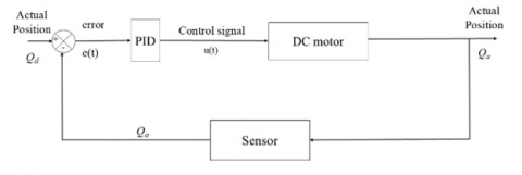
Figure 4 shows the PID controller design for DC motor control. The PID equation is applied to get the control signal for a DC motor. From Eq. (14), e(t) is the position error value difference between the set angle and the output measured angle (actual angle), u(t) is PWM signal for the DC motor, and y(t) is the actual angle. Kp, Ki, and Kd were proportion, integral, and differential coefficient values, respectively.
$u(t)=K_p e(t)+K_i \int_0^t e(t) d t+K_d \frac{d e(t)}{d t}$ (14)
Figure 4. PID block diagram of closed loop position control of the DC motor
The difference between the desired position (Qd) and the actual position (Qa) can be solved using Eq. (15).
$e(t)=Q_d-Q_a$ (15)
For case 1, there are 7 positions, and the distance between each two positions is 38 mm. However, for case 2, there are 4 positions, and the distance between each one is 68 mm. For case 3, there are 16 positions, and the distance between each two positions is 53 mm. In case 4, there are 3 positions, and the distance between each is 153 mm. However, for the Y-axis, each option has 20 mm.
Trial-and-error tuning is applied to evaluate Kp, Kd and Ki. Tuning is applied using different loads. The maximum load the weight exchanger can carry is in the first and second cases. In this case, the maximum load that can carried by the weight exchanger is 3 kg. However, in the third and fourth cases, the maximum load that can carried by the weight exchanger is 10 kg and 60 kg, respectively. For each case, the PID controller was empirically tuned to achieve consistent performance across all calibration cycles. This was accomplished by monitoring the system's steady-state error over multiple cycles using real-time feedback from the Arduino's serial monitor. Table 4 shows the PID controller value for each case. Then, the sequence of calibration is ready to apply for mass calibration.
Table 4. PID controller parameters
|
Controller |
Masses up to 3 kg |
Masses up to 10 kg |
Masses up to 60 kg |
|||
|
Case 1 and 2 |
Option 1 and 2 |
Case 3 |
Option 3 |
Case 4 |
Option 4 |
|
|
Kp |
5 |
8.5 |
7.0 |
10.4 |
11.0 |
18.8 |
|
Kd |
0.1 |
0.1 |
0.1 |
0.1 |
0.1 |
0.1 |
|
Ki |
0.1 |
0.3 |
0.1 |
0.3 |
0.1 |
0.5 |
A premium planetary geared motor with an encoder actuates each axis. Electronic scheme as shown in Figure 5. Arduino Due is used to control the movements of the prototype. Each pin has pulse width modulation. Dual motor controllers are also used to control the motors' positions.
For each case, the maximum error in the x-direction is within 0.03 - 0.05 mm, whereas the maximum error in the y-direction is 0.07 - 0.13 mm. The error in the control signal does not affect the position of the measuring process because the last error is added to the next control signal. Therefore, the error remains constant during the whole measurement.
Figure 5. Electronic scheme of the weight exchanger
5.3 Experimental setup and mass measurement
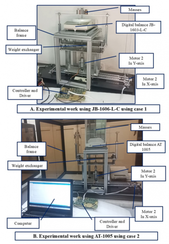
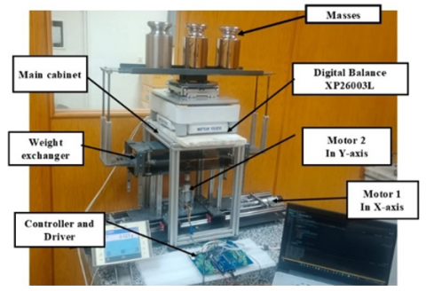
The control design is designed according to the calibration sequence, whether R-T-T-R or R-T-R, according to OIML R-111 [1]. The experimental work uses three digital electronic balances to verify the design parameters. The first case is JB1603-L-C; the maximum capacity is 320 g, and its resolution is 0.1 mg. Therefore, the measurement uses standard masses with class E2 and test masses with low classes M from 50 g up to 200 g. The second and third cases use a high-resolution balance to check the stability of the reading during the measurement process (AT-1005). The maximum capacity of the balance is 1,050 g, and the balance's resolution is 0.01 mg. Therefore, the measurement uses standard masses with class E1 and test masses with classes E2 and F1. The difference between cases 2 and 3 is the number of masses that can be calibrated. The fourth case calibrates mass up to 20 kg using (XP26003L). Therefore, this case can calibrate masses from 2 kg up to 20 kg. The experimental works setup for cases 1, 2 and 4 are shown in Figures 6 and 7.
Figure 6. Experimental work setup using case 1 and 2
Figure 7. Experimental work setup using case 4
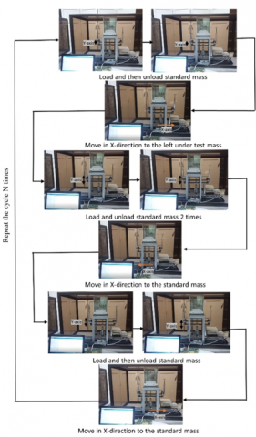
Figure 8. The measurement process for one position snapshot
The main aim of these measurements is to verify the control's parameter while loading different nominal masses. All these masses are traceable to the national prototype No. 58 [30]. Then, the conventional mass for each test mass is calculated using Eq. (1) by comparing the standard and test masses several times. Figure 8 describes the snapshot of the one-cycle measurement procedure.
Table 5. Measurement was carried out using JB1603-L-C manually and automatically using case 1
|
Nominal Mass |
R |
T |
Manual Calibration |
Automatic Calibration |
||
|
(g) |
$\Delta m_{c i}$, (mg) |
Standard deviation, (mg) |
$\Delta m_{c i}$, (mg) |
Standard deviation, (mg) |
||
|
50 |
E2/1 |
M(1) |
-7.75 |
0.38 |
-8.95 |
0.06 |
|
50 |
E2/1 |
M(2) |
-9.37 |
0.30 |
-9.0 |
0.02 |
|
100 |
E2/1 |
M(1) |
11.97 |
0.46 |
11.93 |
0.20 |
|
100 |
E2/1 |
M(2) |
-6.52 |
0.32 |
-5.71 |
0.07 |
|
100 |
E2/1 |
M(3) |
114.67 |
0.51 |
114.52 |
0.12 |
|
200 |
E2/1 |
M(1) |
2.4 |
0.44 |
2.72 |
0.30 |
|
200 |
E2/1 |
M(2) |
106.5 |
0.26 |
106.97 |
0.15 |
Table 6. Measurement was carried out using AT-1005 manually and automatically using case 2 and 3
|
Nominal Value |
R |
T |
Manual Calibration |
Automatic Calibration |
||
|
(g) |
$\Delta m_{c i}$, (mg) |
Standard deviation, (mg) |
$\Delta m_{c i}$, (mg) |
Standard deviation, (mg) |
||
|
200 |
E2/1 |
F1(1) |
0.52 |
0.021 |
0.50 |
0.012 |
|
200 |
E2/1 |
F1(2) |
0.34 |
0.018 |
0.60 |
0.003 |
|
500 |
E2/1 |
F1(1) |
0.01 |
0.019 |
-0.02 |
0.007 |
|
500 |
E2/1 |
F1(2) |
-0.20 |
0.021 |
0.01 |
0.006 |
|
1000 |
E2/1 |
F1(1) |
-4.12 |
0.022 |
-4.10 |
0.010 |
|
1000 |
E2/1 |
F1(2) |
-2.18 |
0.028 |
-2.22 |
0.009 |
Table 7. Measurement was carried out using XP26003L manually and automatically using case 4
|
Nominal Value |
R |
T |
Manual Calibration |
Automatic Calibration |
||
|
(kg) |
$\Delta m_{c i}$, (mg) |
Standard deviation, (mg) |
$\Delta m_{c i}$, (mg) |
Standard deviation, (mg) |
||
|
2 |
E2/1 |
F1(1) |
-3 |
3.3 |
-2 |
1.6 |
|
2 |
E2/1 |
F1(2) |
5 |
4.1 |
3 |
2.1 |
|
5 |
E2/1 |
F1(1) |
7 |
3.1 |
8 |
1.6 |
|
5 |
E2/1 |
F1(2) |
4 |
2.9 |
2 |
2.1 |
|
10 |
E2/1 |
F1(1) |
14 |
2.5 |
13 |
1.1 |
|
10 |
E2/1 |
F1(2) |
12 |
2.3 |
13 |
1.1 |
|
20 |
E2/1 |
F2(1) |
40 |
2.1 |
40 |
1.0 |
|
20 |
E2/1 |
F2(2) |
41 |
2.0 |
40 |
0.9 |
The measurements are done manually and automatically to see their difference, as seen in Table 5.
This table describes the measurement's error and the standard deviation of readings. Another measurement is carried out using case 2 and 3 for masses up to 1,000 g as seen in Table 6. Finally, masses ranging from 2 kg up to 20 kg are measured using case 4 as seen in Table 7.
Thirdly, in XP26003L, the mechanism is examined by changing the desired position and load. However, the model can get the motion from the controller exactly. The results show that the standard deviation of readings is minimized.
Moreover, the standard deviation from the automatic measurement is often less than the balance's resolution. Therefore, the new system can decrease the measurement's standard deviation and uncertainty more than manual work.
This work presents a new idea of designing a low-cost weight exchanger based on balance and design constraints to calibrate number of masses up to 20 kg. The motor size is determined for the 2-Axis mechanism using the root mean square torque. The control scheme is designed according to the calibration sequence. Four cases of design constraints are proposed, ranging from 50 g up to 20 kg.
Cases are manufactured successfully according to design variables, and a PID controller is applied to ensure that the controller can track the required position. The maximum error in the x-direction is within 0.03 - 0.05 mm, whereas the maximum error in the y-direction is 0.07 - 0.13 mm. The Experimental works are done on three digital electronic balances to verify the designed-based concept. The results show that the new design of the weight exchanger can calibrate 7, 4, 16, and 3 masses ranging from 50 g up to 20 kg efficiently. From the measurements, the proposed model can measure test masses with a standard deviation less than the balance's resolution. Moreover, automatic systems' standard deviation is better than manual work's for all cases.
The implemented four cases could illustrate the functionality of our idea. Finally, the new weight exchanger can measure number of masses with the minimum standard deviation according to the design constraint and design variables.
|
$\Delta m_c$ |
The conventional mass difference between a test and a reference mass, mg |
|
$m_{c t}$ |
The conventional mass of the test object, mg |
|
$m_{c r}$ |
The conventional mass of the reference object, mg |
|
$\Delta m_{ci}$ |
The average difference in the conventional mass for n cycles, mg |
|
$\Delta I_i$ |
The indication difference between a test (T) and a reference mass (R), mg |
|
Ci |
The correction factor of the air buoyancy |
|
X1 |
The length of the mass holder, mm |
|
X2 |
The balance width, mm |
|
X3 |
The maximum diameter of the mass over the weight exchanger, mm |
|
X4 |
The small gab distance, mm |
|
a |
The gap distance in the X-axis, mm |
|
Xstr |
The length of the power screw, mm |
|
X5 |
The half distance of the remaining distance of the X-axis, mm |
|
X6 |
The no-mass distance, mm |
|
X7 |
The distance between the two bearings, mm |
|
Hal |
The height of the Aluminum profile of the balance frame, mm |
|
TP |
The thickness of the granite plate over the Aluminum profile, mm |
|
b |
The gab area in Y-axis, mm |
|
Y1 |
The height of the weight exchanger movable frame for Y-axis, mm |
|
Y2 |
The column height, mm |
|
Y3 |
The height of linear guide, mm |
|
Y4 |
The height of the balance frame, mm |
|
Y5 |
The distance between the balance and the mass holder, mm |
|
Y6 |
The movable frame height, mm |
|
Y7 |
The vertical distance between the bottom plate and the end of the fixed coupling, mm |
|
Y8 |
The thickness of the mass holder, mm |
|
Y9 |
The thickness of the balance, mm |
|
Y10 |
The height of the weight exchanger, mm |
|
Ystr |
The vertical distance to load mass on the balance, mm |
|
u(t) |
The PWM signal for the DC motor |
|
kp |
Proportional |
|
ki |
Integral |
|
kd |
Derivative |
|
e(t) |
The error |
|
Qd |
The desired position, mm |
|
Qa |
The actual position, mm |
|
TRMS |
The root means square torque, N.m |
|
Ta |
The acceleration torque, N.m |
|
TL |
The load torque, N.m |
|
TD |
The deceleration torque, N.m |
|
Tss |
The standby torque, N.m |
|
ta |
The time required to accelerate, s |
|
tR |
The time required for running |
|
tD |
The time required to accelerate, s |
|
tss |
The standby time |
[1] Oiml, R. (2004). 111-1, Weights of classes E1, E2, F1, F2, M1, M1-2, M2, M2-3 and M3 Part 1: Metrological and technical requirements. International Organization of Legal Metrology.
[2] Gläser, M. (1999). Change of the apparent mass of weights arising from temperature differences. Metrologia, 36(3): 183.
[3] Davidson, S., Perkin, M., Buckley, M. (2004). The measurement of mass and weight. National Physical Laboratory, 40(5): S310. https://eprintspublications.npl.co.uk/3028/1/mgpg71.pd.
[4] GWP. (2025). Get quality, costs and compliance under control. Mettler Toledo. https://www.mt.com/us/en/home/service/good-weighing-practice.html.
[5] Kliebenschaedel, M. (2015). Mass calibration with robotic mass comparators. In XXI IMEKO world congress “measurement in research and industry August.
[6] Peng, C., Wang, J., Wang, X.L., Wu, D., Zhong, R.L., Hu, M.H. (2022). Research on data processing method based on automatic measurement system of mass in small nominal value. Metrology Science and Technology, 66(5): 29-36. https://doi.org/10.12338/j.issn.2096-9015.2021.0648
[7] Ota, Y., Ueki, M., Kuramoto, N. (2021). Evaluation of an automated mass comparator performance for mass calibration of sub-milligram weights. Measurement, 172: 108841. https://doi.org/10.1016/j.measurement.2020.108841
[8] Solecki, M., Szumiata, T., Rucki, M. (2021). A novel automatic mass comparator with a resolution of 10 ng for calibration of masses below 2 mg. Precision Engineering, 72: 576-582. https://doi.org/10.1016/j.precisioneng.2021.07.006
[9] Wang, J. (2019). Research on vacuum transfer equipment in NIM. IEEE Access, 7: 114014-114020. https://doi.org/10.1109/ACCESS.2019.2935757
[10] Sun, J., Ueki, M., Ueda, K. (2017). Development of a high-accuracy 500 kg mass comparator for improved weight calibration capability. Measurement, 95: 418-423. https://doi.org/10.1016/j.measurement.2016.10.036
[11] Mettler Toledo. (2012). Comparator Balances Brochure, pp. 1-40, https://www.mt.com/us/en/home/library/product-brochures/laboratory-weighing/Mass_Comparators.html.
[12] Sartorius Lab Instruments GmbH. (2024). Mass metrology. https://www.sartorius.hr/media/llncapyk/brochure-en-bro-mass-comparators-e.pdf.
[13] Mass Comparators. https://radwag.com/en/mass-comparators.
[14] Lee, M.S., Kwak, W.Y. (2013). Automatic calibration system for 20 Kg weights by robot and weight magazine. In International Journal of Modern Physics: Conference Series. World Scientific Publishing Company, Singapore, 24: 1360037. https://doi.org/10.1142/S2010194513600379
[15] Ueki, M., Mizushima, S., Sun, J.X., Ueda, K. (2004). Improvement of mass standard up to 20 kg by multiple calibration method. In SICE 2004 Annual Conference, Sapporo, Japan, pp. 450-455.
[16] Ueki, M., Mizushima, S., Sun, J.X., Ueda, K. (2002). Simultaneous calibration of the mass and the volume of weights in the range from 1 kg to 20 kg. In Proceedings of the 41st SICE Annual Conference. SICE 2002, Osaka, Japan, pp. 480-482. https://doi.org/10.1109/SICE.2002.1195448
[17] McLinden, M.O., Bernardini, L., Richter, M. (2025). A hydrostatic comparator for the density determination of solid objects. Metrologia, 62(2): 025003. https://doi.org/10.1088/1681-7575/adad77
[18] Sayed, B.M., Azzam, A.B.S., Abdou, B.M.Z., Eltawil, A.A. (2016). Design, control and optimization of the weighing mechanism for the HWA-NIS up to 20 kg. In 2016 3rd International Conference on Information Science and Control Engineering (ICISCE), Beijing, China, pp. 302-307. https://doi.org/10.1109/ICISCE.2016.74
[19] Hamdy, M., Bayoumi, M.A., Abuelezz, A.E., Eltawil, A.A. (2020). Developing the NIS solid density hydrostatic weighing system up to 20 kg. International Journal of Metrology and Quality Engineering, 11: 8. https://doi.org/10.1051/ijmqe/2020006
[20] Sayed, B.M., Hamdy, M. (2025). Automatic control of hydrostatic weighing apparatus in NIS up to 20kg based on PLC and HMI panel. Instrumentation Mesure Métrologie, 24(2): 187-193. https://doi.org/10.18280/i2m.240210
[21] Stock, M., Barat, P., Pinot, P., Beaudoux, F., et al. (2018). A comparison of future realizations of the kilogram. Metrologia, 55(1): T1. https://doi.org/10.1088/1681-7575/aa9a7e
[22] Borys, M., Fehling, T., Fröhlich, T., Heydenbluth, D., Mecke, M., Schwartz, R. (2006). Design and performance of the new Sartorius 1 kg vacuum mass comparator at PTB. In XVIII Imeko World Congress, Rio de Janeiro, Brazil. pp. 1-4.
[23] Fröhlich, T. (2005). The new sartorius 1Kg-Prototype balance for high precision mass determination and research applications. 2005 NCSL International Workshop and Symposium. https://www.researchgate.net/profile/Thomas-Fehling/publication/314045581_Design_and_Performance_of_the_New_Sartorius_1kg-Prototype_Mass_Comparator_for_High_Precision_Mass_Determination_and_Research_Applications/links/5bbde4d892851c4efd534850/Design-and-Performance-of-the-New-Sartorius-1kg-Prototype-Mass-Comparator-for-High-Precision-Mass-Determination-and-Research-Applications.pdf.
[24] Cusimano, G. (2022). Optimized trapezoidal acceleration profiles for minimum settling time of the load velocity. Machines, 10(9): 767. https://doi.org/10.3390/machines10090767
[25] Yoon, H.J., Chung, S.Y., Kang, H.S., Hwang, M.J. (2019). Trapezoidal motion profile to suppress residual vibration of flexible object moved by robot. Electronics, 8(1): 30. https://doi.org/10.3390/electronics8010030
[26] Prasad, G., Ramya, N.S., Prasad, P.V.N., Das, G.T.R. (2012). Modelling and simulation analysis of the brushless DC motor by using MATLAB. International Journal of Innovative Technology and Exploring Engineering (IJITEE), 1(5): 27-31.
[27] Vikhe, P., Punjabi, N., Kadu, C. (2014). Real time DC motor speed control using PID controller in LabVIEW. International Journal of Advanced Research in Electrical, Electronics and Instrumentation Engineering, 3(9): 12162-12167. https://doi.org/10.15662/ijareeie.2014.0309046
[28] Maung, M.M., Latt, M.M., Nwe, C.M. (2018). DC motor angular position control using PID controller with friction compensation. International Journal of Scientific and Research Publications, 8(11): 149-155. http://doi.org/10.29322/IJSRP.8.11.2018.p8321
[29] Khalifa, M., Amhedb, A.H., Al Sharqawi, M. (2021). Real time DC motor position control using PID controller in LabVIEW. Journal of Robotics and Control (JRC), 2(5): 342-348. https://doi.org/10.18196/jrc.25104
[30] Emira, S., Shaaban, E.R., Rashad, M.M., Gelany, S.A. (2025). 01 development and performance evaluation of the NIS-Watt balance prototype. Journal of Measurement Science and Applications (JMSA), 5(1): 2-9. https://doi.org/10.21608/jmsa.2025.422905