B. M. Sayed*![]() | Mohamed Hamdy
| Mohamed Hamdy![]()
© 2025 The author. This article is published by IIETA and is licensed under the CC BY 4.0 license (http://creativecommons.org/licenses/by/4.0/).
OPEN ACCESS
Automation converts a work process, procedure, or equipment to automatic rather than human operation or control. Measuring solid density with high accuracy is carried out using the hydrostatic weighing method, which is one of the urgent requirements for automation in National Metrology Institutes (NMIs). This paper describes the automatic system for measuring density of solid objects in the National Institute of Standards (NIS). A Programmable Logic Controller (PLC) controller and a Human Machine Interface (HMI) control automatic weighing operation. The system consists of a main cabinet, assembly elevating platform, Mass carrier, and Water bath. The system has three induction motors for automatic calibration; the first motor is used for the assembly elevating platform. The second and third motors are used for mass carriers. This paper provides a complete description of the automation system. The feasibility of the automatic system is described using simulation software. The results of motion and the automatic system enhance the ability of the system control to measure the solid density. Finally, experimental measurements are helpful for automatically measuring the solid density of standard mass ranging from 1kg up to 20kg.
PLC, HWA-NIS, solid density, Archimedes principle, hydrostatic weighing
Automation is delegating human control functions to technical equipment to increase productivity, quality, maintenance cost and safety in working conditions. Programmable Logic Controllers (PLCs) are widely used in various industries for automation and control due to their flexibility and reliability. Here are some exciting Programmable Logic Control (PLC) applications across different industries [1, 2]. During the last 40 years, Early automation relied on mechanical and electromechanical control devices. However, the computer gradually became the leading vehicle of automation [1]. Modern automation is usually associated with computerization. The significant phases of historical development and social and economic aspects of industrial automation focus on computerizing production, engineering, and managerial tasks.
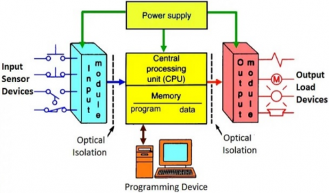
PLC is one of the most widely used industrial control systems [3, 4]. The PLC system is a computer system that consists of various hardware components such as the CPU, programming devices, external hardware components, Input/Outputs (I/O), and power supply. It is an industrial computer that is used to monitor inputs and control the process or make a design based on its control (on/off), as shown in Figure 1 [4]. The input of any machine is in the plant. It is a microcontroller device that senses input from input devices and executes it in the cup, which updates the output module to provide data to output devices.
Figure 1. Block diagram of the PLC system
A control system is a combination of various devices integrated into a system that is used to scene, measure, indicate and control the process variable. This variable indicates the process designed for automation. It takes care of operations in an automated way with minimum human interface.
PLCs operate cyclically, following a continuous loop known as the scan cycle, which includes the following steps:
Firstly, input scan: The PLC reads the status of all input devices and sensors.
Secondly, program execution: Based on the input status and the control program, the PLC processes the logic and determines the necessary actions.
Thirdly, output scan: The PLC updates the status of output devices and actuators based on the processed logic.
Lastly, diagnostics/communication: The PLC performs self-checks and communicates with other systems or PLCs as required.
PLC is used in a wide range of applications in the industry [1, 2, 5, 6]. PLCs are extensively used in manufacturing plants to control assembly lines, conveyors, robotic arms, and packaging systems. They help in improving efficiency, reducing downtime, and ensuring consistent product quality [7-9]. Moreover, PLCs are used in automobile manufacturing for tasks like controlling robotic welding arms, painting systems, and assembly line operations. They can also be used for quality control and testing processes [9]. Pollák et al. [10] describe programming procedures for robotic arms used in industry, PLC automation technology programming, and simulation programs commonly used to verify the functionality of proposed robotic workplace solutions in practice. Recently, PLC is used for design method of intelligent controller for obstacle avoidance and navigation of electrical inspection mobile robot [11]. PLCs play a crucial role in food processing and packaging plants by controlling mixing, cooking, filling, and packaging processes [12-14]. PLCs are used in water treatment plants to control pumps, valves, chemical dosing systems, and filtration processes. PLC with HMI panel is used to present the design and automation control of milk pasteurization process in the dairy industry using a Siemens S7-300 PLC and online monitoring [15]. Designing and implementation of a PLC enhances performance and energy efficiency of steam boilers through adjusting the pH value and total dissolved solids in boiler water [16]. PLCs are employed in building management systems to control HVAC (Heating, Ventilation, and Air Conditioning) systems, lighting, access control, and security systems. PLCs are used in traffic control systems, railway signaling systems, and Automated Guided Vehicles (AGVs) for efficient and safe transportation operations. PLCs are utilized in oil refineries, pipelines, and offshore platforms to control drilling operations, pipeline monitoring, and refinery operations. PLCs are used in pharmaceutical manufacturing to control processes like mixing, filling, labeling, and packaging medicines. In measuring solid density, manual work cannot measure the density of solid objects accurately because of the disposal of water while putting the mass from/to the balance. Moreover, the user cannot ensure that the mass is weighed at the center of the balance pan because of the illumination of the water. Therefore, the automatic weighing for measuring solid density is urgent for accurate measurement. The accurate measurement is urgent for NMIs because it can be used for measuring conventional mass accurately. Therefore, traceability can be achieved for the reference masses in each NMI.
HWA-NIS is a device to measure solid density accurately up to 20kg using a hydrostatic weighing technique. This technique is based on weighing in two different mediums. Weighing process should be carried out at the center of the mass. The solid object weighs in the air to find its mass. Then, it weighs in distilled water to find the displaced liquid by the object immersed in it. This operation must operate automatically by comparing two artifacts in weighing in air and in distilled water. The first one is the standard mass with known mass and density while the other is unknown mass and density. The system consists of the main cabinet, the balance pan, the mass carrier, the assembly elevating platform and the thermostatic water bath. The mass carrier has two motors. The first one is used to load/unload a mass on a balance pan. The second motor is used to rotate masses about a particular axis. The assembly elevating platform is motorized to change the weighing medium (air or liquid).
This process is controlled using PLC and touch screens (HMI) to create a user-friendly user interface. The circuit diagram is described and simulated using a simulation software package. Then, the process of weighing is presented using PLC's ladder diagram. After that, the system will operate automatically after conducting the ladder diagram. Finally, a series of measurements, the system is excellent for measuring solid density automatically.
The primary function of the HWA-NIS is to measure the solid density according to Archimedes principle [17-19]. It can measure the solid density of test mass ranging from 1kg up to 20kg. This operation can be applied by comparing a standard and test mass according to method 2 in OIML R111 Recommendation [20, 21]. The standard mass, its mass, and its density are known. Therefore, the operation should be executed automatically to compare the mass and volume of the standard mass and test mass in air and liquid. The system has five sub-systems: The main cabinet, balance pan, mass carrier, assembly elevating platform and the thermostatic water bath, as shown in Figure 2.
Figure 2. HWA-NIS main subsystems
The mass carrier has two axes for motion (vertical and rotational motion) [19]. This motion is actuated using two induction motors. The vertical motion is transferred using a power screw and nut. The power screw is attached to motor 1 (M1) using coupling. Four linear guides and bearings are used to minimize friction. M1 is used to weigh the mass when it is concentric with the balance pan. The second motor (M2) rotates the masses about a particular axis. This motor is used to select whether mass will be weighed. The assembly elevating platform is actuated using an induction motor (M3). Two power screws are used to transfer the rotational motion to linear motion. Chain and sprockets are used to transfer the motion from the M3 to the two power screws. Therefore, three motors are used to operate the system. Motor 1 (M1) loads and unloads the mass on the balance pan. Motor 2 (M2) selects which mass between the standard and test masses to weigh. Motor 3 (M3) is used to change the weighing medium to weigh both masses in two different mediums (air and distilled water).
All these motors and the thermostatic water baths must operate automatically according to OIML R111 [21]. Therefore, using a PLC is one of the most reliable sources for automating a sequence of operation for these motors.
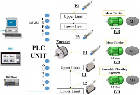
The system has three motors that need to be controlled according to the sequence of operation. Each motor will operate in a forward and reverse direction. This sequence can be achieved using PLCs, electronic devices programmed to control the sequence of operations. Figure 3 illustrates the main components for automatic control of the HWA-NIS.
Figure 3. Schematic diagram for controlling elements
Three proximity switches are added. The first one is used for home position detection. This signal will allow the encoder to operate motor 2 (M2) according to motion control angle-step. The used encoder has one step, so each step equals 1o. The first motor (M1) must operate forward and reverse according to constant stroke. Therefore, two proximity switches are added. The first (P2) is used for the upper limit, while the other (P3) is used for a lower limit. An assembly elevating platform changes the medium of weighing from air to liquid and vice versa. Motor 3 (M3) is used for this operation. Therefore, two limit switches are added. The first is used for the upper limit (L1), while the second is for the lower limit (L2).
Figure 4. Wiring system diagram for controlling HWA-NIS
The full description of the electrical diagram is shown in Figure 4. Reverse forward motor control circuits are used to control the direction of rotation of a three-phase motor. The main components are as follows:
K7M-DR40U PLC, three three-phase induction motors, six poles (Molded Case Circuit Breaker) MCCB, six poles (Miniature Circuit Breaker) MCB, six magnetic contactors, thermal overload relay, 400-480V three phase supply, 230V Single phase supply and 24V DC supply as shown in Figure 4.
The direction of rotation of the motor is controlled by reversing the phase sequence of the supply to the motor. A PLC can be used to control the reverse forward motor.
The reverse forward motor control circuit is a three-phase motor control circuit that controls the direction of rotation of the motor. The control circuit consists of two contactors, a thermal overload relay, and a PLC. The contractors are used to reverse the phase sequence of the supply to the motor, and the thermal overload relay is used to protect the motor from overloading. The PLC is used to control the contactors and to monitor the status of the thermal overload relay. Thermal overload consists of three thermal coils connected in series to the motor and it has a current setting to be adjusted according to motor current. In case of motor current is greater than the overload current setting for any reason such as overload, phase disconnection, etc, the overload thermal coils temperature is increased then expanded and disconnect NC contact inside the overload. The overload NC contact is connected externally to the contactor coil, so it disconnects the main contactor contacts and hence disconnects the motor.
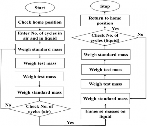
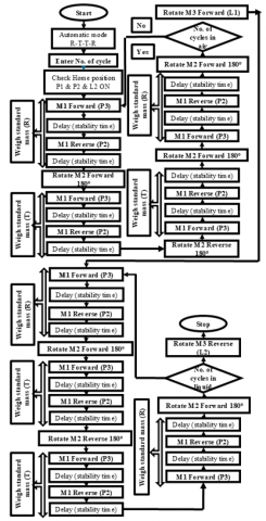
The sequence is controlled according to OIML R111. The sequence of operation is carried out as shown in Figure 5.
Figure 5. Block diagram of the controlling system
The sequence is operated using the R-T-T-R sequence of operation in air and liquid. R refers to the weight of reference mass, while T refers to test mass. Firstly, the user should enter No. of cycles which No. of repeat the sequence of operation R-T-T-R. The double shield water bath is thermostatically stable, and the user enters the reference temperature value of 20℃. The water bath is controlled using a PID controller. The control of the water bath is shown in Figure 6.
Figure 6. Block diagram of controlling temperature of the water bath
It comprises a double shield water bath, cooler, heater, pump, temperature sensor and PID control unit. The diagram shows an automatic temperature control loop. It consists of a sensor to measure the temperature, a controller and a power regulator. The controller compares the measured temperature with the desired temperature, called the setpoint, and regulates the output power to make them the same. The error signal is the difference between the setpoint and the measured value. Firstly, the PLC controller will check the home position before weighing. The home position is P1, L2, and P2 are ON. When P1 is ON, it will set the encoder angle to 0o. Then, the calibration process will start by weighing the standard mass. This operation is controlled using PLC to operate M1 forward until it reaches the next proximity sensor (P3).
Then, M1 will operate in the reverse direction until it reaches upper proximity (P2). Then, (M2) will rotate 180o until the test mass will be concentric to the balance pan. After that, the weighing process for test mass two times will start. Test mass will be weighed by operating M1 in forward and reverse directions. This process is controlled using P2 and P3 for upper and lower limits, respectively. Then, the mass carrier will operate (M2) until the standard mass is concentric with the balance pan. Then, the standard mass will load and unload using (M1), P2 and P3 proximity sensors. Then, the process will be repeated until the No. of cycles. The weighing in air is finished. Then, (M3) will operate until the limit switch 1 (L1) is reached. Therefore, the masses are now immersed in the distilled water. Then, all previous sequences of weighing operation will be repeated in the distilled water using a sequence of operation R-T-T-R. After that, M3 will operate until it reaches the lower limit switch (L2). The sequence of operations has been finished, and the system is ready for the subsequent measurement.
The sequence of operation is controlled using the PLC module (Master-K120S). The model is k7M-DR40U. This type has 24 inputs and 16 outputs. A touch screen is also used (XP 30), which can ease the interface with the controller, and the user can check the position of each motor. The No. of input pins is 13 pins, while No. of output pins is 6 pins. Table 1 describes the primary function for each pin. Then, the user can enter No. of cycles, the delay between each weighing process and the delay time before starting the measurement. Finally, the process will start. This sequence of operation is programmed and organized using a PLC ladder diagram. It is the most widely used software language for a sequence of regular operations.
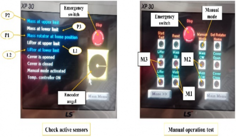
The system can be controlled manually using the touch screen to test motors, manual calibration checks, or the presence of active sensors as shown in Figure 7.
Figure 7. Manual calibration switches
Table 1. PLC inputs and outputs pins
|
Input Pins |
Output Pins |
|
Emergency switch |
M1 forward direction |
|
M1 forward switch |
M1 reverse direction |
|
M1 reverse switch |
M2 rotates in CW |
|
M2 CW |
M2 rotates in CCW |
|
M2 CCW |
M3 forward direction |
|
M3 forward switch |
M3 reverse direction |
|
M3 reverse switch |
----- |
|
Inputs parameters |
----- |
|
P1 home position |
----- |
|
P2 (upper limit) mass carrier |
----- |
|
P3 (lower limit) mass carrier |
----- |
|
L1 (upper limit) assembly elevating platform |
----- |
|
P3 (lower limit) assembly elevating platform |
----- |
The blue indicates that the used sensor is active, while the white indicates that the sensor is inactive. An emergency switch is added for any fault.
However, automatic control is used for the calibration process, and each operation takes more than three hours depending on the number of cycles, the delay time before starting the test and the delay time between each weighing process (stability time).
For automatic calibration, the sequence of the calibration process is shown on Figure 8. All sensors are normally open. Firstly, HWA-NIS checks that the home positions P1, P2, and L2 are ON. Then, the weighing process is ready to start. M1 operates in a forward direction till it reaches (P3). After that, stability time to let the balance be stable. Then, M2 rotates 180o in the forward direction. Now, the test mass is ready to weigh. M1 operates in a Reverse direction till it reaches (P2). After that, stability time to let the balance be stable. They are weighing reference mass (R). Then, the (T) mass is weighed again using (P3) and (P2) in forward and reverse directions. Then, M2 rotates 180o in reverse direction. Now, the reference mass is ready to weigh. Then, the (R) mass is weighed again using (P3) and (P2) in forward and reverse directions. Then, the number of cycles will be checked. If No. of cycles is not equal to the set value, the weighing process will be repeated. Else, M3 will be actuated till reaching (L1). Then, the weighing process will be repeated according to the number of cycles after the masses are immersed in the distilled water. Finally, M3 will be actuated till reaching (L1).
Figure 8. Sequential full-description block diagram of the controlling system
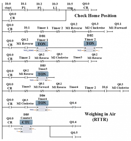
Figure 9. Ladder diagram of the automatic mode
The ladder diagram as shown in Figure 9 describes the weighing process of the operations.
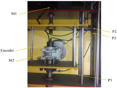
The experiment was carried out using the HWA-NIS system, balanced with model XP26003. The balance resolution is 1mg, PLC unit, Muman Machine Interface (MHI), reference standard with known conventional mass and density as seen in Table 2. The distance between P2 and P3 is 30mm. The screw's pitch is 4mm. Then, the time required to load or unload a mass is 90 sec. Similarly to the assembly elevating platform, the screw pitch is 6mm. For M2, the time required to rotate masses 180o is 30 sec. The distance between L1 and L2 is 500mm. The deduction between chain and sprocket is 2:1. Then, the time required to change the medium from air to liquid is 285.7 sec. HWA-NIS system has three motors as described in Table 3. The HWA-NIS system set-up is shown in Figure 10. Touch screen and control unit circuits, including motors and sensors. The system has two modes of operation: Manual and automatic mode. Automatic mode is examined practically by weighing different nominal masses (1, 2, 5, 10 and 20) kg in air and liquid. The system operates perfectly and follows the sequence of operations exactly using an inverter to control the speed of M3. This inverter keeps the motor safe without slipping from the center of the mass carrier. Some measurements are carried out by weighing both air masses and distilled water. The mass carrier is shown in Figure 11, including three proximity sensors and an encoder.
Table 2. Standard mass value
|
Nominal Mass (kg) |
Conventional Mass |
Density (kg.m-3) |
|
1 |
1kg+0.282mg |
8008.0 |
|
2 |
2kg–0.49mg |
8007.6 |
|
5 |
5kg–0.42mg |
8009.1 |
|
10 |
10kg–0.13mg |
8008.1 |
|
20 |
20kg–1.0mg |
8015.7 |
Table 3. The speed of each motor
|
Motor |
Speed (rpm) |
Power (HP) |
|
M1 |
5 |
0.25 |
|
M2 |
4 |
0.33 |
|
M3 |
35 |
0.50 |
Figure 10. Experemintal setup
Figure 11. Experimental setup for mass carrier
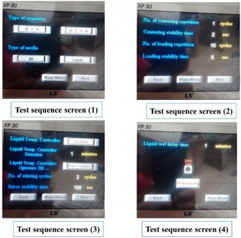
The touch screen is programmed with PLC to facilitate the weighing process. Figure 12 explains the channels of the HWA-NIS control sequence. Users can check the active sensor and the angle of the encoder using channel (1). The active sensor is blue, while the other is inactive. Moreover, the user can select the weighing sequence (R-T-R) or (R-T-T-R) and the weighing medium (air or liquid) using channel 2. No. Of cycles, centering stability time, No. of centering cycles, and No. Stability time can be selected using channel 3. Channel 4 controls the thermostatic water bath using a timer to make the water bath temperature within 20℃. The next Channel is used for the start test. The user can operate the system using the touch buttons shown in the last channel for manual work. During the automatic operation, the user should follow the experiment using the status of each sensor and encoder angle. Then, Eq. (1) is used to determine the density of the solid object based on OIML R111 recommendations (method A2) [20].
Figure 12. HMI automatic setting channels
$\rho_t=\frac{\rho_l\left(C_a m_r+m_{w a}\right)-\rho_a\left(C_l m_r+m_{w l}\right)}{m_r\left(\frac{\rho_l-\rho_a}{\rho_r}\right)+\Delta m_{w a}-\Delta m_{w l}}$ (1)
where, $\rho_{\mathrm{t}}$ is the density of test object, $\rho_l$ is the density of the distilled water, $\rho_{\mathrm{a}}$ is the density of the air density, $\mathrm{C}_{\mathrm{a}}$ is the correction of the air buoyancy when weighing in air, $\mathrm{C}_{\mathrm{l}}$ is the correction of the liquid buoyancy when weighing in liquid, $\mathrm{m}_{\mathrm{r}}$ is the conventional mass of the reference mass, $\mathrm{m}_{\mathrm{w a}}$ is the mass difference between standard mass and test mass in air, $\mathrm{m}_{\mathrm{w l}}$ is the mass difference between standard mass and test mass in liquid.
$\mathrm{C}_{\mathrm{a}}$ and $\mathrm{C}_{\mathrm{l}}$ can be calculated according to the following Equations.
$C_a=1-\frac{\rho_a}{\rho_r}$ (2)
$C_l=1-\frac{\rho_l}{\rho_r}$ (3)
where, $\rho_{\mathrm{r}}$ is the reference density, which is 8000kg.m-3. Air density, $\rho_{\mathrm{a}}$, is 1.2kg.m-3.
A series of measurements are carried out to validate automatic control. The sequence of the measurement is as follows:
Firstly, the water bath's temperature should be within 20℃. The stability time should be between 30 to 90 sec. The time before starting the test depends on the temperature of the water bath. Then, start weighing in the air. Table 4 describes the measurement in air. Table 4 describes the difference between reference and test mass while weighing in air. Then, both masses are immersed in the distilled water to get the difference in weighting. Then, the density of the solid object can be calculated using Eq. (1). As seen in Table 4, a set of measurements is carried out using the automatic system ranging from 1kg up to 20kg to validate the operation control.
Table 4. Results of the automatic weighing process
|
Nominal Mass (kg) |
mwa |
mwl |
ρt |
|
1 |
-1 |
+3 |
8005.9 |
|
2 |
-2 |
+21 |
8008.3 |
|
5 |
-6 |
+41 |
8009.7 |
|
10 |
-9 |
+2 |
8006.7 |
|
20 |
+1 |
+85 |
8004.6 |
PLCs are a cornerstone of modern industrial automation, providing the versatility and control needed to optimize manufacturing processes and ensure efficiency. HWA-NIS controls the motion of the HWA-NIS to measure the solid density for standard masses ranging from 1kg up to 20kg. HMI facilitates the weighing process, allowing users to follow the active sensor and motor in action. Motor 1 uses two proximity sensors, while Motor 3 is controlled using two limit switches. Motor 2 is controlled using a rotary encoder and proximity switch to set the home position of the system. The obtained results prove the feasibility of the automatic system. The designed system is successfully controlled using a PLC unit to measure solid density ranging from 1kg to 20kg. The obtained results prove the new system's ability to measure solid density automatically.
|
Ca |
dimensionless heat source length |
|
Cl |
specific heat, J. kg-1. K-1 |
|
mr |
the conventional mass of reference mass |
|
mwa |
the mass difference between standard mass and test mass in air |
|
mwl |
the mass difference between standard mass and test mass in liquid |
|
Greek symbols |
|
|
ρa |
the density of the air density |
|
ρl |
the density of the distilled water |
|
ρt |
the density of test object |
|
Subscripts |
|
|
NMIs |
National Metrology Institutes |
|
NIS |
National Institute of Standards |
|
PLC |
Programmable Logic Control |
|
HWA |
Hydrostatic Weighing Apparatus |
|
MHI |
Machine Human Interface |
|
HVAC |
Heating, Ventilation, and Air Conditioning |
|
MCCB |
Molded Case Circuit Breaker |
|
AGVs |
Automated Guided Vehicles |
[1] Basile, F., Chiacchio, P., Gerbasio, D. (2012). On the implementation of industrial automation systems based on PLC. IEEE Transactions on Automation Science and Engineering, 10(4): 990-1003. https://doi.org/10.1109/TASE.2012.2226578
[2] Satyanarayana, S.V., Pranavi, P.V., Reddy, P.D. (2018). Multifunctional smart energy system by internet of things. Journal of Engineering Research and Application, 8(11): 47-48. https://www.ijera.com/papers/vol8no11/p1/I0811014748.pdf.
[3] Zhou, M., Twiss, E. (1998). Design of industrial automated systems via relay ladder logic programming and Petri nets. IEEE Transactions on Systems, Man, and Cybernetics, Part C (Applications and Reviews), 28(1): 137-150. https://doi.org/10.1109/5326.661096
[4] Bryan, L.A., Bryan, E.A. (1997). Programmable controllers: Theory and implementation. Industrial Text Company.
[5] Alheraish, A., Alomar, W., Abu-Al-Ela, M. (2006). Programmable logic controller system for controlling and monitoring home application using mobile network. In 2006 IEEE Instrumentation and Measurement Technology Conference Proceedings, Sorrento, Italy, pp. 469-472. https://doi.org/10.1109/IMTC.2006.328543
[6] Xiao, Z., Cai, T., Zhang, Y., Liu, Z., Peng, W. (2011). The automatic control system based on PLC in concrete's grouting and vibrating project. In 2011 Second International Conference on Mechanic Automation and Control Engineering, Hohhot, pp. 5358-5361. https://doi.org/10.1109/MACE.2011.5988203
[7] Dixit, A., Mendiratta, R., Chaudhary, T., Kumari, N. (2015). Review paper on PLC & its applications in automation plants. International Journal of Enhanced Research in Science Technology & Engineering, 4(3): 63-66.
[8] Şahin, H., Güntürkün, R., Hız, O. (2020). Design and application of PLC controlled robotic arm choosing objects according to their color. Electronic Letters on Science and Engineering, 16(2): 52-62.
[9] Fredmer, A. (2017). Application and Control of Robotic Manipulator through PLC.
[10] Pollák, M., Kočiško, M., Goryl, K. (2023). PLC control of a 2-axis robotic arm in a virtual simulation environment. In Design, Simulation, Manufacturing: The Innovation Exchange. Cham: Springer Nature Switzerland, pp. 50-59. https://doi.org/10.1007/978-3-031-32767-4_5
[11] Liu, Z., Li, M., Fu, D., Zhang, S. (2024). Design of intelligent controller for obstacle avoidance and navigation of electric patrol mobile robot based on PLC. Scientific Reports, 14(1): 13476. https://doi.org/10.1038/s41598-024-63810-5
[12] Hambir, P., Joshi, N., Karande, P., Kolhe, A., Karande, P. (2019). Automatic weighing and packaging machine. International Research Journal of Engineering and Technology (IRJET), 7(5): 2395-0072.
[13] Mahalik, N.P., Yen, M. (2009). Extending fieldbus standards to food processing and packaging industry: A review. Computer Standards & Interfaces, 31(3): 586-598. https://doi.org/10.1016/j.csi.2008.03.027
[14] Xuan, K., Gu, G. (2022). Optimisation of multi-channel to single channel control method for food packaging line based on PLC. International Journal of Manufacturing Technology and Management, 36(2-4): 112-126. https://doi.org/10.1504/IJMTM.2022.123658
[15] Kumaresan, K., Deepa, R., Dhanasekar, R., Monisha, C.C., Dasaprakash, C., Priyavarshini, G.U. (2018). Design and automated control of pasteurization process in dairy industry using S7-300 PLC and HMI. In National Conference on Control Instrumentation System Conference. Singapore: Springer Nature Singapore, pp. 329-337. https://doi.org/10.1007/978-981-99-9554-7_25
[16] Sami, H.A., Ibrahim, R.I., Oudah, M.K., Naeem, B.S. (2024). Fouling and corrosion control of steam boiler tube using PLC system. Petroleum Chemistry, 64(1): 151-158. https://doi.org/10.1134/S0965544124020142
[17] Hamdy, M., Bayoumi, M.A., Abuelezz, A.E., Eltawil, A.A. (2020). Developing the NIS solid density hydrostatic weighing system up to 20kg. International Journal of Metrology and Quality Engineering, 11: 8. https://doi.org/10.1051/ijmqe/2020006
[18] Sayed, B.M., Azzam, A.B.S., Abdou, B.M.Z., Eltawil, A.A. (2016). Design, control and optimization of the weighing mechanism for the HWA-NIS up to 20kg. In 2016 3rd International Conference on Information Science and Control Engineering (ICISCE), Beijing, China, pp. 302-307. https://doi.org/10.1109/ICISCE.2016.74
[19] Sayed, B.M., Azzam, B.S., Abdou, M.Z., Eltawil, A.A. (2014). A new precise apparatus for solid density measurement up to 10kg. Advanced Materials Research, 909: 127-134. https://doi.org/10.4028/www.scientific.net/AMR.909.127
[20] de Metrologie Legale, O.I. (2004). OIML R111-1 Weights of Classes E1, E2, F1, F2, M1, M1-2, M2, M2-3 and M3. OIML. Paris.
[21] Hayu, R., Sutanto, H., Ismail, Z. (2019). Accurate density measurement of stainless steel weights by hydrostatic weighing system. Measurement, 131: 120-124. https://doi.org/10.1016/j.measurement.2018.08.033