Nadya Husain Muslim*![]() | Ali R. Yousif
| Ali R. Yousif![]()
© 2025 The authors. This article is published by IIETA and is licensed under the CC BY 4.0 license (http://creativecommons.org/licenses/by/4.0/).
OPEN ACCESS
Centrifugal pumps are one of the most important mechanical equipment used in several industrial fields, the design and development of this equipment must be carefully done to obtain higher efficiency. This study focused on the effect of blade inlet angle and blade outlet angle on the movable energy and efficiency of centrifugal pumps at different flow rates and velocities. The maximum pressure was obtained in Impeller No. 4 at a 70º inlet angle and a 5 Kg/sec flow rate while the maximum efficiency was obtained in Impeller No. 5 at a 3.5 kg/sec flow rate. The experimental work also considered the effect of blade number on 2-D impellers using different types of impellers with two diffusers, one of which is a helical diffuser, and the other is a multi-blade diffuser. The performance curve results of each Impeller at different speeds (1100 and 1200 rpm) were compared to get the best specs when it comes to movable energy pressure and flow rates. The current findings showed that the shape of the Impeller passages affects pump properties and blade number; besides, the angle of the inlet and outlet of blades is controlled by the movable energy.
centrifugal pump, impeller blades, helical diffuser, movable energy, centrifugal pump efficiency
Impeller blade shape modulation and its effect on centrifugal pump performance was studied in this work; the blade-let technique was used to modulate the impeller blade shape. The airplane winglet is like a centrifugal pump blade; the shape of the trailing edge of the pump blade has a high effect on turbo machine performance. The high-pressure difference causes the pump blade to reduce flow recirculation at the trailing edge of the pump. There are two parameters in this research - the radial position (Rb) and the blade's inclined angle. ANSYS program software was used to study the blade-let technique effect following simulation with different parameters [1-3].
A centrifugal pump with a semi-open impeller has been studied experimentally and numerically by Gen [4]; the study found more impact of side clearance on the performance of the centrifugal pumps and modified the impeller blades by cutting them with different geometrical parameters. The performance of the pump was discussed, including the pump head, blade loads, internal flow structure, efficiency, and slip factor.
Numerically, Waluyo and Waluyo [5] investigated the variation in pump performance with the number of blades, and the results showed that hydrodynamic efficiency was higher in the case of 7 blades when matched with the two other flow rates that were simulated. A plot of the head and flow rate in the form of a head-efficiency plot verses the flow rate produced the same pattern, indicating an optimum number of blades for the centrifugal pump.
The performance of the centrifugal water pump impeller at varying loads was numerically investigated using mathematical methods [6]. The study found that the pressure of the fluid on the impeller significantly influenced the performance of the impeller as it caused the impeller to experience high stress and deformation. A diffuser with/without a van on three walls with deformation angles (0, 5, and 10º) was also used for the experimental and numerical studies. Better performance of the centrifugal pump was also reported when using different diffusers on the lower flow side for the impeller of the pumps. The numerical and experimental results were combined to reveal differences in the van angle between the head and the efficiency of the centrifugal pump (head = 15.4 and overall efficiency = 9 % at the van diffuser angle, a = 10º) [7-10].
The effect of adding splitter blades and altering their geometry on the performance of the impeller of a centrifugal pump has been optimized [8] via experimental and numerical studies and from the results, the addition of splitters can bring about 10.6% improvement in total head and their geometry alteration by the DoE technique can increase the total head by an extra 4.4 % without considering their effect on the overall efficiency of the pump. The design and selection of centrifugal pumps were also studied by Han et al. [9] who found that the mechanical-to-kinetic energy ratio and pressure energy varied with increases in the impeller diameter for pumps with different impeller diameters. Also, they reported that the shift in energy performance is associated with changes in impeller flows, chamber, and diffuser. Meanwhile, Susilo and Setiawan [10] discussed the performance of impeller-related pumps and analyzed the impacts of blades number and impeller blades angle on the discharge pressure of centrifugal pumps. The impeller suction was determined by the number and angle of the blades. The experimental and simulation studies showed that an increase in the number of blades decreased the discharge. In their relationship of pump performance with flow rate, it was found that an increase in the blade number caused a decrease in the flow rate, and the highest flow was 404.91 l/s for two blades at 130° while the lowest flow rate was 279.66 l/s for six blades at 160°.
The integration of experimental and numerical analyses provides comprehensive insights into flow patterns, energy conversion, and the relationship between vortex formation and pump performance, offering valuable guidelines for future pump design optimization [11, 12]. These studies collectively investigated various parameters that influence the performance of centrifugal pumps, particularly focusing on blade geometry and its impact on hydraulic efficiency, head, and flow characteristics. A common theme across the research is the significant effect of the blade outlet angle and number of blades on pump performance [13, 14].
The outlet angle of the blades has a direct impact on the performance and pattern of the internal flow in high-speed submersible pumps, so this angle can improve the performance of the pump significantly by reducing its energy loss and increasing the efficiency of hydraulic conversion [15]. However, the outlet angle on impeller blades have been studied for ability to prevent submersible centrifugal pump overload by Han et al. [15]; the study was performed at a specific low speed for multi-submersible pumps at different outlet angles (16º, 20º, 24º, 28º, & 32º). From the results, the outlet blade angle has significant impact on the power curve and flow characteristics, but can be controlled to prevent overload by reducing the outlet angle. Increasing the blade outlet angle led to an increase in a low-pressure area, which causes cavitation. Therefore, it was determined that the angle of b2 = 16 was the better angle to prevent cavitation as it provides better flow [16].
In the study by Peng et al. [17], flow analysis was conducted on a heavy-duty slurry pump integrated into a receiving hopper located on a grinding circuit in an ore dressing plant. The study sought to determine the flow characteristics of the slurry in the pump under different particle concentrations, as well as under small volumetric flow rates. It was found that the slurry flow at low flow rates exhibited significant unsteadiness with significant backflow and intense local abrasion. Additionally, as the particle concentration increased, flow resistance increased and so did backflow, resulting in a further exacerbation of local wall abrasion. A field test was also conducted on a grinding circuit slurry pump and the results revealed that the largest most serious local abrasion phenomena matched the results of the modeling, which were penetration and sliding wear. The design and manufacture of Impeller blade plays an important role in the efficiency of pumps, as angles and curves greatly affect the flow of fluids. Finite element technology is a powerful tool for the analysis and design of complex products such as pump fins. This technology allows a deep understanding of the impact of different parameters on performance and efficiency and thus achieves significant design improvements [18].
A quantitative study of the impact of a pre-whirl and a modified blade profile on the hydraulic performance and cavitation flow of centrifugal pumps was explored by Song et al. [19] through numerical simulations. The results showed that increasing the pre-whirl angle results in a lower friction loss and thereby a higher hydraulic efficiency for an off-design flow rate, whereas the head coefficients for no pre-whirl are higher than those for designs with pre-whirl.
In the literature, several studies have been carried out on the subject of centrifugal pump performance and the consequent overall performance analysis of a centrifugal pump. There is a gap in the literature regarding how the combined effects of blade inlet angle, blade outlet angle, and blade number affect the pump’s efficiency and total energy (or head produced by a centrifugal pump) over different flow rates and impeller speeds. Most research has focused on the individual behaviour of the blade parameters or the effect of blade inlet and outlet angles independently. Furthermore, there is a lack of a comprehensive analysis of how these factors interact with each other in affecting the pump’s performance. This is important for the overall optimization of any centrifugal pump design and pump energy savings in different industrial applications.
However, in feature, some aspects, such as the impact of specific blade geometries on fluid dynamics, could be further elaborated upon to strengthen the theoretical underpinnings.
It can graphically simulate any point in liquid flow passing through the impeller using a velocity triangle. The critical aspect is the simulated velocity vectors at the inlet and outlet of the impeller. When the impeller is rotating through an outer source, an increase in the absolute angular moment for streamlining liquid during impeller passages can be acquainted with the state as follows:
$M=m \cdot\left(r_2 \cdot v_2 \cdot \sin \alpha_2-r_1 \cdot v_1 \cdot \sin \alpha_1\right)$ (1)
where, the velocity of the liquid is given as:
$M=m \cdot\left(r_2 \cdot R o_2-r_1 \cdot R o_1\right)$ (2)
The transmission energy from the impeller to the liquid passing through it is given as:
$Power=M .(S R)=m \cdot\left(r_2 . R o_2 . S R-r_1 . R o_1 . S R\right)$ (3)
where=r. SR, t:
Therefore, Eq. (3) is given as:
$Power=m \cdot\left(R o_2 \cdot C_2-R o_1 \cdot C_1\right)$ (4)
The design state regards the absolute velocity component (Ro1) as equal to zero; then, there is no absolute angular moment at the liquid inlet to the impeller. The work done (transmission energy) is given as:
$Pump \, Effecency =\frac{Waterpower}{Pump power}=\frac{P_w}{P_p}$ (5)
$ Power =C_2 \cdot R o_2=g \cdot H_{t h}$ (6)
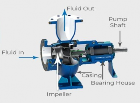
In this study, the experimental work is performed in Al-Mussaib institute laboratories, the laboratory equipment used to measure centrifugal impeller properties is shown in Figures 1 and 2; it consists of a pump fitted vertically, which connects directly with the electric motor via coupling. This equipment contains a pipe grid and valve group, as well as a water tank for frequency absorption such that it can deliver liquid pressure and steady flow. The A5 impeller was used for the study; this impeller differed in blade number, outer angle, inner angle of the blade, and diffuser type as illustrated in Table 1.
Figure 1. Flow systematic and gauge equipment
Figure 2. Details of the centrifugal pump
Table 1. Properties of the used impellers
|
Blade Number |
Inner Angle |
Outer Angle |
Blade Shape |
Impeller Digit |
|
1 |
Circular |
65º |
70º |
8 |
|
2 |
Straight |
30º |
70º |
8 |
|
3 |
Straight |
30º |
70º |
11 |
|
4 |
Circular |
0º |
70º |
8 |
|
5 |
Straight |
0º |
0º |
8 |
The electronic tachometer mechanism provides the velocity of rotation of the impeller; the venture meter provides the flow rate; the value of the flow rate is taken from an electronic digital counter; the pressure value at the pump inlet is taken from the Burton gage such that this apparatus’ right pressure at impeller inlet may also be maintained using this gage; another mercury manometer is used to measure the pressure difference in the impeller inlet and outlet. The value of this pressure represents the produced energy value for every size unit from the liquid, i.e., for a known volume of liquid. The subjected torque on the pump is measured to the distance from the motor using the connected helical spring as shown in Figure 1; a curly spring is used here to calculate the outer and inner energy of the pump.
4.1 Angle changing effect of blade outlet
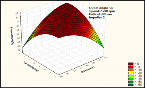
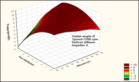
The inlet angle of the blade has a high effect on liquid movable energy and pump efficiency, and reducing this angle leads to an increase in the value of the generated pressure, as well as the binding of a constant circumference speed because of the reduced outlet angle due to increase in the rotation component of the absolute liquid speed, thereby increasing both the absolute angular momentum and the absolute speed. This speed increase leads to the loss of the produced kinetic energy as it transforms into pressure energy in the diffuser, thereby reducing the pump efficiency. The performance curves for Impeller 1, Impeller 2, and Impeller 4 can compare the outlet angle effect on efficiency value and movable energy to liquid at a constant speed. The static program is used to draw all figures of results in three dimensions. Figures 3, 4, and 5 show the pressure value changes and efficiency with different flow rates at 1200 rpm for the three impellers (1, 2, and 3). The inlet angle of the blade is a major factor that determines how effectively a pump converts mechanical energy into fluid flow. By reducing the inlet angle, the fluid dynamics in a pump can be modified, especially the flow speed and direction as the fluid enters the pump.
Figure 3. The relationship between flow rates, pressure, and efficiency at the impeller outlet angle of 65º
Figure 4. The relationship between flow rates, pressure, and efficiency at the impeller outlet angle of 30o
Figure 5. The relationship between flow rates, pressure, and efficiency at the impeller outlet angle of 0o
By lowering the inlet angle of the blade, the pressure generated by the pump can be improved, while reducing the angle causes an improvement in the liquid’s speed part of the rotation, which equates to an increase in both absolute angular momentum and speed. This pressure increase comes at a cost, however, because, as the fluid speed increases, losses occasioned by the transformation of kinetic energy into pressure energy in the diffuser section of a pump also increase. These losses ultimately degrade a pump’s overall efficiency. Therefore, Figures 3, 4, and 5 showed that Impeller No. 4 had higher pressure than Impeller No. 2 and 1. In contrast, the efficiency of Impeller No. 1 was higher than the other impellers at a wide range of flow rates, especially at a relatively higher flow rate of >8 Kg/sec.
4.2 Angle changing effect of blade inlet
The liquid inlet angle of the impeller reflects the specific angle between the radius sprawl of the impeller and the relative speed at the inlet. The reason for selecting the best inlet angle is to reduce the influence of pre-rotation phenomena, which reduces pressure value (movable energy). The performance curves of Impeller No. 4 and No. 5 can be compared according to the difference in blade inlet angle. Figures 6 and 7 showed changing pressure values and efficiency at the rotation speed of 1200 rpm with flow rate for the two impellers.
Figure 6. The relationship between flow rates, pressure, and efficiency at the impeller inlet angle of 70o
Figure 7. The relationship between flow rate, pressure, and efficiency at the impeller inlet angle of 0o
Figures 6 and 7 showed that impeller No. 4, with an inlet angle of 70o, had higher pressure than impeller No. 5 with an inlet angle of 0o. The pressure value of impeller No. 4 was higher at a flow rate of 5Kg/sec, but began reducing after that, even reaching a value less than the pressure of impeller No. 5 at a flow rate of 7 Kg/sec; the efficiency of impeller No. 4 was less than the efficiency of impeller No. 5 at relatively low flow rates (3.5 Kg/sec). Impeller No. 4 had higher efficiency than impeller No. 5 at more considerable flow rates (3.5 Kg/sec).
4.3 Blades number changing effect
The value of movable energy can be obtained from Eq. (5); the blade's number imposes an infinity number. The liquid flow in impeller passages is represented only in major flow, i.e. the value of relative speed deviation at the outlet is equal to zero. The difference between the ideal state and the applicable state is limited by the slip factor. The deviation factor mainly depends on the number of blades in the impeller. Hence, the increase in blade number is due to an increase in slip factor. The theoretical slip factor is calculated by the following equation [20-22]:
$\mu=1-\frac{0.63}{n}$ (7)
Figure 8. Effect of blade number on flow rate, pressure, and efficiency for impeller No. 2
The performance curves of impellers No. 2 and 3 were compared at a constant speed and the blade number was noted to affect the movable energy value and pump efficiency at 1100 rpm and different flow rates, as seen in Figures 8 and 9.
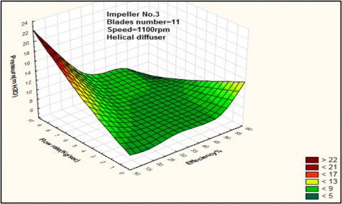
Figure 9. Effect of blades number on flow rate, pressure, and efficiency for Impeller No. 3
Figures 8 and 9 show the effect of blade number on pressure (movable energy) and efficiency. The blade number of impeller No. 3 is 11 and its pressure value is higher than that of impeller No. 2 with 8 blades. Evidently, an increase in blade number led to an increase in slip factor and momentum value. The increase in friction due to the increasing blade number is less than the increase in angular momentum because of the increase in movable energy from the impeller to the liquid. The efficiency of impeller No. 3 in Figures 8 and 9 is more significant than that of impeller No. 3, and the flow rate is less than 4 kg/sec; the difference between them is higher at a flow rate greater than 4 kg/sec. The increase in the blade number of impellers led to increased friction loss and increased flow rates. The increase in friction loss in impeller No. 3 compared to the friction loss of impeller No. 2 is smaller at low flow rates (less than 4 kg/sec); there is also a slight increase in efficiency in impeller No. 3 compared to impeller No. 2.
4.4 Diffuser type changing effect
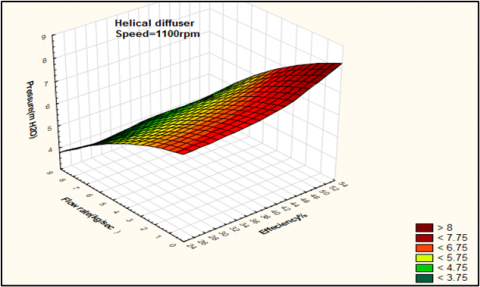
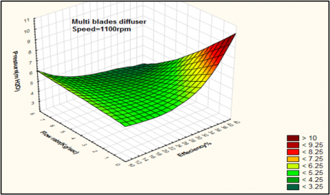
The performance curve for impeller No. 1 with a diffuser with blades and a helical diffuser can be compared in terms of the changing pressure value (movable energy and efficiency) with flow rates at a constant speed when using two diffusers with one impeller (see Figures 10 and 11).
Figure 10. Helical diffuser effect on values of pressure, efficiency, and flow rate
Figure 11. Multi-blade diffuser effect on pressure, efficiency, and flow rate
Figures 10 and 11 show diffuser-type changing effects on pressure and efficiency values at 1100 rpm using the same impeller. Impeller No. 1 was used with a helical diffuser that gives better pressure value (movable energy) and more significant efficiency compared to impeller No. 1 with a multi-blade diffuser at different flow rates. There is errs ratio between theoretical and experimental results about 5% approximately, and in experimental work negligible.
This paper investigated the intricate interplay between various parameters responsible for the performance of impellers in pump systems. By analyzing the effects of blade inlet and outlet angles, number of blades, and diffuser types on static pressure coefficient, total pressure coefficient, and isentropic efficiency for a number of impellers, a valuable set of conclusions was made in this work. The best impeller performance in terms of pressure was discovered to be achieved by impeller No. 4 with a 70° inlet angle and 5 kg/sec flow rate. Similarly, the best impeller performance in terms of efficiency was found to be achieved by impeller No. 5 at a flow rate of 3.5 kg/sec. The analysis of 2-D impellers with different diffusers (multi-blade diffuser and helical diffuser) clearly showed the great influence of the shape of an impeller on the properties of the pump and ducting characteristics.
Based on the experimental and simulation studies in this work, the following results were achieved:
(i) The shape of the impeller passages affects the pump properties significantly, as well as the number of blades and the angles of incidence (θ1) and deviation (β2) which are the most important in controlling kinetic energy; so, an impeccable design is required to optimize the pump performance.
(ii) Increasing the number of blades and adjusting the outlet angles by choosing the suitable θ1 can remarkably increase the head level within specific limits. This can be proven by the trends in Figures 5 and 9; it means that the impeller design can be fine-tuned to achieve the desired performance metrics.
(iii) The performance study on the diffusers showed that helical diffusers are a better choice. The diffuser type influences the pump performance; hence, the present study can guide the selection of diffuser types during the design process.
(iv)The findings represent a significant advancement into the intricacies of impeller performance as it relates to pump systems; they also provide valuable insight into the optimization of pump design and operation parameters. Such insights are invaluable in enhancing the performance of pumping technologies across a wide spectrum of industrial applications.
|
V1 |
Absolute speed for liquid at impeller inlet. |
|
V2 |
Absolute speed for liquid at impeller outlet. |
|
g |
Gravitational acceleration, m.s-.2 |
|
Ro1, Ro2 |
Rotation component for absolute speed at impeller inlet and outlet. |
|
Hth |
Local Nusselt number along the heat source. |
|
M |
Absolute angular moment. |
|
Q |
Mass flow rate (Kg/sec). |
|
n |
Blades Number |
|
r1, r2 |
Impeller radius at inlet and outlet. |
|
C1, C2 |
Impeller circumference speed at inlet and outlet. |
|
SR |
Impeller rotational speed. |
|
Greek Symbols |
|
|
$\phi_1, \phi_2$ |
Relative angle to enter and exit of liquid. |
|
$\alpha_1, \alpha_2$ |
Absolute angle to enter and exit of liquid. |
|
Ɵ |
Dimensionless temperature. |
|
µ |
Slipping factor. |
[1] Hassan, A.F.A., Abdalla, H.M., Aly, A.A.E.A. (2017). Centrifugal pump performance enhancement by blade shape modification. In Turbo Expo: Power for Land, Sea, and Air, 50794: V02BT41A001. https://doi.org/10.1115/GT2017-63023
[2] Youcefi, S., Mokhefi, A., Bouzit, M., Youcefi, A. (2023). Energy-efficient design optimization of two-bladed agitators in cylindrical tanks. International Journal of Heat & Technology, 41(6): 1489-1501. https://doi.org/10.18280/ijht.410611
[3] Tian, Y., Hu, A. (2018). Study on critical speed of rotation in the multistage high speed centrifugal pumps rotors. International Journal of Heat & Technology, 36(1): 31-39. https://doi.org/10.18280/ijht.360105
[4] Gen, M. (2015). Experimental and computational study of semi-open centrifugal pump. Doctoral Dissertation, Military Technical College. http://dx.doi.org/10.13140/RG.2.1.5190.3766
[5] Waluyo, J., Waluyo, R. (2021). Performance comparison of centrifugal pump in variation of impeller blade number through numerical simulation. AIP Conference Proceedings, 2403(1). https://doi.org/10.1063/5.0074344
[6] Yadeta, L., Lemu, H.G. (2023). Numerical analysis of centrifugal water pump impeller under varying loads. IOP Conference Series: Materials Science and Engineering, 1294(1): 012022. http://dx.doi.org/10.1088/1757-899X/1294/1/012022
[7] Khoeini, D., Shirani, E., Joghataei, M. (2019). Improvement of centrifugal pump performance by using different impeller diffuser angles with and without vanes. Journal of Mechanics, 35(4): 577-589. https://doi.org/10.1017/jmech.2018.39
[8] Namazizadeh, M., Talebian Gevari, M., Mojaddam, M., Vajdi, M. (2020). Optimization of the splitter blade configuration and geometry of a centrifugal pump impeller using design of experiment. Journal of Applied Fluid Mechanics, 13(1): 89-101. http://dx.doi.org/10.29252/jafm.13.01.29856
[9] Han, Y., Li, H., Tiganik, T., Wang, Y., Zhou, L. (2023). Influence mechanism of trimming impeller diameter in a centrifugal pump by computational fluid dynamics investigation. Journal of Fluids Engineering, 145(2): 021205. https://doi.org/10.1115/1.4056210
[10] Susilo, S.H., Setiawan, A. (2021). Analysis of the number and angle of the impeller blade to the performance of centrifugal pump. EUREKA: Physics and Engineering, (5): 53-61. https://doi.org/10.21303/2461-4262.2021.002001
[11] Jiang, J., Li, Y.H., Pei, C.Y., Li, L.L., Fu, Y., Cheng, H.G., Sun, Q.Q. (2019). Cavitation performance of high-speed centrifugal pump with annular jet and inducer at different temperatures and void fractions. Journal of Hydrodynamics, 31: 93-101.
[12] Babayigit, O., Kocaaslan, O., Aksoy, M.H., Guleren, K.M., Ozgoren, M. (2015). Numerical identification of blade exit angle effect on the performance for a multistage centrifugal pump impeller. EPJ Web of Conferences, 92: 02003. https://doi.org/10.1051/epjconf/20159202003
[13] Li, X., Chen, B., Luo, X., Zhu, Z. (2020). Effects of flow pattern on hydraulic performance and energy conversion characterisation in a centrifugal pump. Renewable Energy, 151: 475-487. https://doi.org/10.1016/j.renene.2019.11.049
[14] Sakran, H.K., Abdul Aziz, M.S., Abdullah, M.Z., Khor, C.Y. (2022). Effects of blade number on the centrifugal pump performance: A review. Arabian Journal for Science and Engineering, 47(7): 7945-7961. https://doi.org/10.1007/s13369-021-06545-z
[15] Han, C., Liu, J., Yang, Y., Chen, X. (2023). Influence of blade exit angle on the performance and internal flow pattern of a high-speed electric submersible pump. Water, 15(15): 2774. https://doi.org/10.3390/w15152774
[16] Peng, G., Chen, Q., Zhou, L., Pan, B., Zhu, Y. (2020). Effect of blade outlet angle on the flow field and preventing overload in a centrifugal pump. Micromachines, 11(9): 811. https://doi.org/10.3390/mi11090811
[17] Peng, G., Huang, X., Zhou, L., Zhou, G., Zhou, H. (2020). Solid-liquid two-phase flow and wear analysis in a large-scale centrifugal slurry pump. Engineering Failure Analysis, 114: 104602. https://doi.org/10.1016/j.engfailanal.2020.104602
[18] Abbas, A.A., Hussein, M.A., Mohammad, M.M. (2005) Design parameters estimation and design sensitivity analysis in manufacturing process of rubber pad by using finite element technique. International Journal of Mechanical & Mechatronics Engineering, IJMME-IJENS, 18(3): 75-85. http://doi.org/181603-5252/i2m.210402
[19] Song, P., Wei, Z., Zhen, H., Liu, M., Ren, J. (2022). Effects of pre-whirl and blade profile on the hydraulic and cavitation performance of a centrifugal pump. International Journal of Multiphase Flow, 157: 104261. https://doi.org/10.1016/j.ijmultiphaseflow.2022.104261
[20] Capurso, T., Stefanizzi, M., Pascazio, G., Ranaldo, S., Camporeale, S.M., Fortunato, B., Torresi, M. (2019). Slip factor correction in 1-D performance prediction model for PaTs. Water, 11(3): 565. https://doi.org/10.3390/w11030565
[21] Balacco, G. (2018). Performance prediction of a pump as turbine: Sensitivity analysis based on artificial neural networks and evolutionary polynomial regression. Energies, 11(12): 3497. https://doi.org/10.3390/en11123497
[22] Vasanthakumar, P., Krishnaraj, J., Karthikayan, S., Vinoth, T., Sankar, S.A. (2017). Investigation on reverse characteristics of centrifugal pump in turbine mode: A comparative study by an experimentation and simulation. Materials Today: Proceedings, 4(2): 693-700. https://doi.org/10.1016/j.matpr.2017.01.074