Nail Alaoui* | Boukhalfa Aicha Amel | Zeggar Aya![]()
© 2024 The authors. This article is published by IIETA and is licensed under the CC BY 4.0 license (http://creativecommons.org/licenses/by/4.0/).
OPEN ACCESS
Reconfigurable antennas are pivotal in advancing the versatility of modern wireless communication devices, allowing operation across diverse frequency bands, polarizations, and radiation patterns. This study introduces a tri-band frequency reconfigurable planar monopole antenna that leverages a shortened metal ground plane and a 1.6 mm thick FR-4 substrate to enhance its adaptability in multi-band wireless applications. Our innovative design utilizes optical switching to transition between dual-band and single-band operational modes: Enabling Wi-Fi at 2.4 GHz and WLAN at 5.65 GHz in the dual-band mode, and WiMAX at 3.5 GHz in the single-band mode when the optical switch is toggled off. The antenna's configuration not only fulfills the demanding multi-frequency requirements of contemporary portable devices like laptops, PDAs, and smartphones but also caters to specific applications in safety and rescue operations due to its compact, low-profile, and lightweight design. Performance evaluations demonstrate robust functionality with optimal frequency reconfigurability, highlighted by a VSWR below 2 across all operational bands, making it a prime candidate for future scalable wireless systems.
dual-frequency mode, dual band, WIFI, Reconfigurable, WIMAX, monopole, WLAN, dual frequency mode, switchable
In response to the escalating demand for diverse services on contemporary communication devices such as smartphones, iPads, PDAs, and laptops, the necessity for antennas capable of transmitting and receiving signals across multiple frequency bands has become increasingly critical. This imperative arises from the prevalence of various wireless applications, each requiring specific frequency allocations to operate seamlessly—applications such as WLAN (5.4 GHz), Wi-MAX (3.5 GHz), Bluetooth (2.4-2.48 GHz), UMTS (1.92-2.18 GHz), PCS (1.85-2 GHz), and GSM (1.712-1.17 GHz) [1-10]. Recent advancements in 5G technology and the proliferation of IoT devices have further emphasized the need for versatile communication systems that these antennas must support.
This diversification in wireless applications underscores the need for antennas that can effectively accommodate the distinct frequency requirements of these technologies. Whether it's the higher frequencies associated with WLAN and Wi-MAX or the lower frequencies utilized by Bluetooth and GSM, a versatile antenna design is paramount for ensuring optimal performance across the spectrum of modern communication services. As such, the design and implementation of antennas capable of efficiently operating in multiple frequency bands have become a focal point in contemporary wireless communication research and development.
Multi-band antennas, capable of transmitting and receiving signals over various frequency bands while maintaining maximum radiation efficiency, directivity, and gain, are often referred to as multi-band antennas. Although there is a benefit to providing different services with a single antenna, a disadvantage is that the antenna is specifically calibrated to operate in all the frequency bands it is intended for. To overcome this constraint, the antenna's radiating element includes switches such as PIN diodes, optical switches, and varactors, which may be used to selectively enable or disable various frequency bands [10-17]. These antennas are known as frequency-reconfigurable antennas, which allow a single antenna to fulfill the various requirements of many applications, leading to a decrease in manufacturing costs and dimensions [18-26].
The pursuit of efficient frequency-reconfigurable planar monopole antennas has been a key focus for researchers due to their appealing attributes, including cost-effectiveness, compact size, and compatibility with multiple frequency bands. Over time, various radiating elements such as B-shaped, E-shaped, G-shaped, F-shaped, C-shaped, and double T-shaped have been employed in the construction of these antennas, often accompanied by diverse switching strategies [27-30]. The choice of these specific shapes and switches is based on their proven ability to provide wider bandwidth and superior gain, while the inclusion of advanced switching mechanisms like PIN diodes and optical switches enhances frequency agility and reduces signal interference.
Planar and printed monopole antennas emerge as viable options for modern wireless devices, given their ability to perform effectively across a range of frequency bands. Researchers have explored different techniques for modifying the resonant frequencies of these antennas, employing varactors, lumped components, optical switches, and PIN diodes to achieve frequency reconfigurability [31-35]. This adaptability makes them well-suited for the dynamic requirements of modern wireless communication systems.
The designed antennas are not only compatible with current standards like Wi-Fi 6 and LTE but are also engineered to be adaptable for upcoming technological evolutions, ensuring longevity and relevance in rapidly advancing wireless landscapes.
This work outlines the methodology for designing and simulating two planar monopole antennas that possess the ability to assume an extensive range of configurations. A substrate comprising FR4 material, measuring 1.6 millimeters in thickness, is employed in the fabrication process of the antennas. Wi-Fi, WLAN, and WiMAX frequency channels are all presently capable of being utilized with the recommended antennas.
The following parts of the work are arranged as follows: The design process for the monopole reconfigurable antenna is described in Section II. Section III offers a comprehensive elucidation of the acquired results. Section IV compares to previously work research. Section V of the paper includes the conclusion.
This section provides an explanation of the fundamental geometric and design concepts that underpin the proposed antenna, which is capable of functioning across many frequency bands and can be modified. In order to achieve the capability of altering frequencies, the simulation makes use of a condensed RLC equivalent circuit that is composed of pin diodes. This design technique allows the antenna to work at different frequencies by changing the ON/OFF state of the diodes. This allows the antenna to perform at multiple frequencies. This results in improved efficiency as well as strong performance in the distant field, particularly when a partial ground plane is used.
2.1 Geometry and design theory
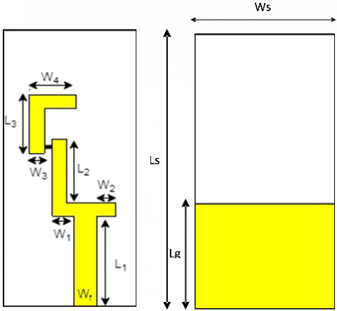
The geometry and structural dimensions of the tri-band frequency reconfigurable antenna, which is expressly engineered for WLAN, Wi-Fi, WiMAX and applications, are shown in Figure 1. The radiating element of the antenna is manufactured onto a FR-4 substrate characterised by a tangent loss (tan δ) of 0.019 and a relative permittivity (εr) of 4.5. By utilising this commercially available substrate while FR-4 is a practical and economical choice for many applications such as WIFI, WIMAX, WLAN, its limitations at higher frequencies should be carefully considered in the context of the specific requirements of the antenna application, the antenna design is rendered more practicable and economical. To attain gain, optimal efficiency and directivity, a truncated metallic ground surface is utilised. The use of a partial ground plane in antenna designs is grounded in its ability to manipulate the antenna's impedance, resonance, and radiation pattern to enhance performance, particularly in the far-field to ensure optimal performance outcomes. The activation of the antenna is achieved via a 50-microstrip line that is designated for the waveguide interface and has a width of 3 mm. As depicted in Figure 1, the radiating structure comprises a slot, with a slot measuring 1 mm in width. This configuration facilitates the incorporation of lumped-element switches. The monopole antenna being examined has the following dimensions: 33 × 16 × 1.6 mm3. Table 1 presents a succinct overview of the precise dimensions pertaining to the antenna proposal.
Figure 1. The geometry of the frequency reconfigurable: (a) Front view; (b) Rear view
Table 1. Presents the frequency reconfigurable antenna detailed dimensions
|
Parameters |
Values (mm) |
|
W4 |
8.3 |
|
L3 |
8.5 |
|
W3 |
2 |
|
L2 |
9.1 |
|
W1 |
3 |
|
W2 |
2.5 |
|
L1 |
11.5 |
|
Wf |
3 |
|
Ls |
33 |
|
Ws |
16 |
|
Wg |
16 |
|
Lg |
7.5 |
The determination of the effective resonant lengths for particular frequencies is achieved by employing the theory of transmission lines [31]. A correlation exists between the resonant bands and the effective lengths (Lf = λf/4), which correspond to a quarter of the guided wavelength for each frequency. The aforementioned computation yields significant insights regarding the antenna's resonance characteristics at various frequencies, thereby facilitating a comprehensive comprehension of the manner in which the antenna engages with guided wavelengths within each distinct band. The utilisation of the transmission line model theory enables a precise analysis of the resonant properties of the antenna, thereby facilitating the development and refinement of its operational characteristics across a range of frequencies.
2.2 Reconfigurability
The suggested antenna introduces a novel method to attain frequency reconfigurability by actively manipulating the OFF and ON states of individual PIN diodes.
PIN diodes offer high power handling, robustness, and effective on/off switching, compared to varactor diodes, which are not ideal for binary switching. MEMS switches, on the other hand, exhibit slower switching speeds and are less durable under high power or stress.
This manipulation induces changes in the short and open circuit characteristics between the radiating patches of the antenna. The controlled toggling of these PIN diodes allows for dynamic adjustments to the antenna's operating frequency, offering a versatile solution for applications requiring adaptability to varying frequencies. This innovative approach provides a means to effectively modify the impedance matching conditions of the antenna, thereby influencing its resonant frequency. The resulting capability to dynamically switch between different configurations enhances the antenna's versatility, making it well-suited for communication systems that demand flexibility in adapting to diverse signal frequencies or changing environmental conditions.
The antenna being shown demonstrates two distinct working modes, each characterised by a distinct arrangement of resonant frequencies. When SW1 is turned off, the antenna functions at a frequency of 3.5 GHz. In Mode 2 (with SW1 turned on), the antenna exhibits dual-band characteristics, operating at frequencies of 2.4 GHz and 5.65 GHz. Table 2 provides a comprehensive description of the PIN diodes' conditions in each mode and their corresponding frequency bands.
Table 2. Displays specifications of the PIN diodes for various frequency ranges
|
S. No. |
Mode 1 |
Mode 2 |
|
Switch (SW1) |
ON |
OFF |
|
Frequency Modes |
Dual-band 2.4 GHz and 5.65 GHz |
Single-band 3.5 GHz |
2.3 Switching technique
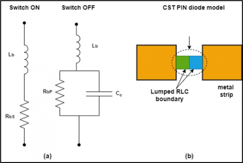
Within the domain of RF frequencies, PIN diodes serve as adjustable resistors, but with significantly more intricate circuitry for both the activated and deactivated states. Both states of PIN diodes in the analogous circuit are characterised by the presence of an inductance (Lb). More precisely, when the diode is in the ON state and biassed in the forward direction, it has low resistance (RbS). On the other hand, when the diode is in the OFF state and biassed in the reverse direction, the PIN diode's equivalent circuit comprises a parallel combination of resistance (RbP) and capacitance (Cc), as depicted in subgraph (a) of Figure 2. In subgraph (b) of Figure 2, the PIN diodes are intended to function as two compact RLC boundary conditions. The reconfigurable properties of the proposed antenna have been simulated solely in terms of resistance, neglecting the values of capacitance and inductance. This omission is justified by the fact that, in the ON state, both the RLC lumped model and the PIN diode model exhibit a short-circuit phenomenon, allowing current to flow easily along the radiating path. Conversely, in the OFF state, both models demonstrate an open-circuit phenomenon, impeding the flow of electric current.
The PIN diode model represents the ON state as a series RL component with low values, simulating a short circuit, facilitating current flow through the radiator. Conversely, the OFF state in the PIN diode is represented as a parallel RLC component with values that simulate an open circuit, inhibiting the passage of electric current through the radiator. For simplicity in the model, the focus has been placed on the open-circuit and short-circuit characteristics. The switch is represented by an RLC lumped element model, with resistance values being the only parameters considered. A low-value resistor (RbS) of 1 Ω functions as a short circuit, enabling unimpeded current flow. In contrast, a high-value resistor (RbP) of 1 MΩ prevents current flow through the radiating structure, resulting in an open-circuit behaviour, C=0.17 pF, L=125 nH.
Figure 2. Model of PIN diode and corresponding circuits for ON and OFF states
The performance of the antenna is evaluated via an exhaustive procedure that includes the creation, modelling, and analysis of its radiating structure utilising CST Microwave Studio 2014. When the antenna is stimulated via a waveguide port, critical performance indicators including directivity, VSWR, gain, reflection coefficient, surface electric field, and far-field pattern are taken into account in the evaluation. By incorporating open-add-space boundary conditions into simulations, a comprehensive evaluation of the antenna's performance and behaviour can be achieved, enabling an accurate depiction of its interactions with the surrounding environment. This methodology offers significant observations regarding the antenna's efficacy, ability to concentrate, and distribution of electromagnetic fields, thereby enabling optimisation in accordance with particular design specifications.
3.1 Bandwidth and return loss
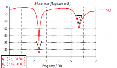
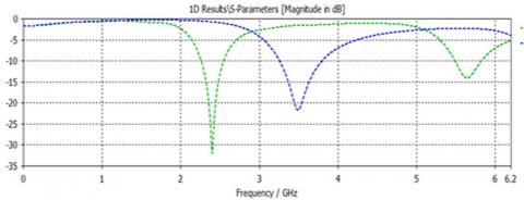
The expected return loss of the proposed antenna is shown in Figure 3, which includes all of its modes. When all of the switches (SW1) are in the OFF position, the proposed antenna operates in Mode 1, which is the default mode. There are two unique frequency bands that the antenna resonates at while SW1 is in the ON state. These frequency bands are 2.4 GHz and 5.65 GHz. These bands have return loss values of -31.884 dB and -14.08 dB, respectively, when compared to two other bands. A bandwidth of 320 MHz (2.24–2.56 GHz) and 380 MHz (5.45–5.83 GHz) are the frequencies that are used by these bands the specified bandwidth of 320 MHz exceeds the typical Wi-Fi band and the 380 MHz bandwidth aligns well with the upper part of the 5 GHz band.
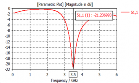
The second mode of the antenna, known as MODE 2, displays resonance at a frequency of 3.5 GHz, and it also has a return loss of -21.237 decibels. The bandwidth that is simulated for this mode is 570 MHz, and it may range anywhere from 3.25 GHz to 3.82 GHz.
The 570 MHz bandwidth encompasses the entire range typically used for WiMAX.
(a) Simulated S11 values for Mode 1
(b) Simulated S11 values for Mode 2
(c) Simulated S11 values for Mode 1 and Mode 2
Figure 3. Simulated S11 values for all operating modes
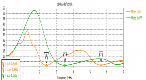
Figure 4. VSWR of proposed antenna
Figure 4 displays a comparison of the simulated S11 for each mode. The findings demonstrate a strong concurrence between the simulated values. Furthermore, the VSWR stays below 2 for all resonant bands, indicating that the antenna has achieved excellent matching. The VSWR values for all frequency bands in use consistently remain below 2, as seen in Figure 4. The VSWR values are below 2 is a good indicator of adequate matching between the transmission line and the load, typically implying minimal signal reflections which can degrade performance.
3.2 Far field pattern
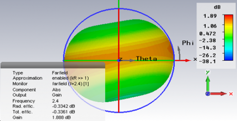
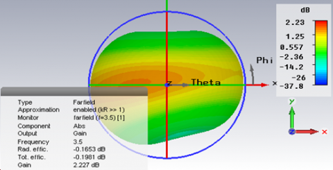
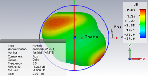
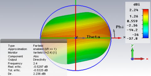
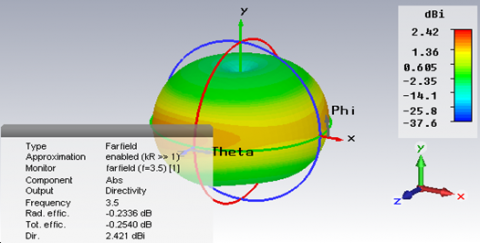
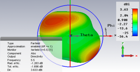
When operating in MODE 1, the antenna that is proposed works at frequencies of 2.4 GHz and 5.6 GHz, a dual band is achieved in Mode 1, which is the operational mode. Peak gain and directivity for the 2.4 GHz band are calculated to be 1.888 dBi and 2.387 dBi, respectively, according to the simulation this gain is generally modest but adequate for common Wi-Fi scenarios such as home networks, public hotspots, and industrial environments. the priority often lies in reliable connectivity rather than maximum performance. It has been determined that the peak gain and directivity of the 5.6 GHz band are 2.236 dBi and 3.633 dBi, respectively. In the mode of operation known as Mode 2, the antenna has a gain of 2.227 dBi and a directivity of 2.421 dBi while operating at a frequency of 3.5 GHz.
Higher frequencies like the 5 GHz band used in WLAN applications benefit significantly from this slightly higher gain. This frequency band is preferable for supporting higher data rates, essential for applications such as HD video streaming or large file transfers. In WiMAX, this gain helps maintain signal strength over larger distances, thus ensuring stable connectivity across urban or rural settings where WiMAX networks are commonly deployed, respectively.
The details are shown in Figures 5 and 6.
(a) 2.4GHz
(b) 3.5 GHz
(c) 5.6 GHz
Figure 5. The 3D gain pattern
(a) 2.4 GHz
(b) 3.5 GHz
(c) 5.6 GHz
Figure 6. The 3D directivity pattern
3.3 The surface current
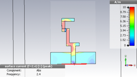
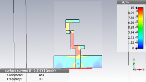
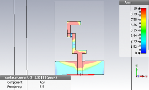
The distribution of surface currents on the radiating structure of the antenna is shown in Figure 7, which covers a number of different frequency bands. Dual band activities, which include 2.4 and 5.6 GHz, are carried out by the antenna while it is operating in Mode 1. Every single vertical arm of the proposed antenna emits radiation while it is operating at the higher frequency end, which is the 5.6 GHz band. Particularly responsible for radiation at lower frequencies (2.4 GHz), the bottom part of the vertical arm is the primary source of radiation. The bottom portion of the vertical arm is primarily responsible for radiation when the Mode 2 antenna is operating at a frequency of 3.5 GHz, as shown in Table 3.
(a) 2.4 GHz
(b) 3.5 GHz
(c) 5.5 GHz
Figure 7. Surface current distribution for Antenna
Table 3. Overview of the antenna's efficacy
|
Parameters |
State of the Switch |
|
|
ON |
OFF |
|
|
Frequency (GHz) |
2.4 and 5.65 GHz |
3.5 GHz |
|
Gain (dB) |
1.888 and 2.387 dBi |
2.227 dBi |
|
Return Loss (dB) |
-31.884 and -14.08 |
-21.237 |
|
Directivity (dBi) |
2.236 and 3.633 |
2.421 |
|
VSWR |
1.0522 and 1.4928 |
1.1805 |
|
Band Width (MHz) |
320 (2.24–2.56 GHz) and 380(5.45–5.83 GHz) |
570 (3.25–3.82 GHz) |
The comparison of the suggested antenna with the previously mentioned literature is presented in Table 4. The table demonstrates that the proposed antenna is smaller in size when compared to [32-35]. The suggested antenna has several benefits. First, it has a small and condensed form, making it appropriate for situations where there is a scarcity of room. Furthermore, the antenna is cost-efficient, offering a budget-friendly alternative without sacrificing performance. The lightweight architecture of the product promotes its adaptability and makes it easy to integrate into other systems. Finally, the uncomplicated assembly method streamlines the installation of the antenna, guaranteeing efficient deployment in various environments.
Our antennas might be better for mobile devices due to their small size.
This study successfully introduces a tri-band frequency reconfigurable antenna designed specifically for IEEE 802.11 Wi-Fi, WLAN, and WiMAX applications. Achieving functionality across multiple frequencies through the innovative use of a switch mechanism, the antenna operates at 2.4 GHz for Wi-Fi, 5.65 GHz for WLAN, and 3.5 GHz for WiMAX. Constructed using commercially available FR4 substrates of 1.6 millimeters thickness, the antenna's design leverages compactness and cost-efficiency without sacrificing performance, making it ideal for space-constrained applications. Despite the successes, the study acknowledges potential limitations such as the reliance on the durability of the switch mechanism and performance variability under different environmental conditions. These challenges highlight areas for future research, including the exploration of more robust materials and technologies to enhance signal reliability and operational bandwidth. The antenna's lightweight construction and straightforward assembly process further ensure its adaptability and ease of integration into diverse systems, making it a practical solution for both commercial and industrial applications. Its introduction is poised to significantly benefit the field of wireless communications by providing a versatile, economical, and efficient technological solution. Future investigations could focus on optimizing the antenna's design to increase its frequency range and developing advanced integration techniques to further its application in emerging wireless technologies.
[1] Nejdi, I.H., Rhazi, Y., Lafkih, M.A., Bri, S. (2020). A High gain reconfigurable frequency antenna multiband for wireless communications. In 2020 International Symposium on Advanced Electrical and Communication Technologies (ISAECT), Marrakech, Morocco, pp. 1-6. https://doi.org/10.1109/ISAECT50560.2020.9523654
[2] Nikolaou, S., Bairavasubramanian, R., Lugo, C., Carrasquillo, I., Thompson, D.C., Ponchak, G.E., Papapolymerou, J., Tentzeris, M.M. (2006). Pattern and frequency reconfigurable annular slot antenna using PIN diodes. IEEE Transactions on Antennas and Propagation, 54(2): 439-448. https://doi.org/10.1109/TAP.2005.863398
[3] Kim, B., Pan, B., Nikolaou, S., Kim, Y.S., Papapolymerou, J., Tentzeris, M.M. (2008). A novel single-feed circular microstrip antenna with reconfigurable polarization capability. IEEE Transactions on Antennas and Propagation, 56(3): 630-638. https://doi.org/10.1109/TAP.2008.916894
[4] Boti, M., Dussopt, L., Laheurte, J.M. (2000). Circularly polarised antenna with switchable polarisation sense. Electronics Letters, 36(18): 1518-1519. https://doi.org/10.1049/el:20001098
[5] Saraswat, R.K., Kumar, M. (2015). A frequency band reconfigurable UWB antenna for high gain applications. Progress In Electromagnetics Research B, 64: 29-45. https://doi.org/10.2528/PIERB15090103
[6] Osman, M.N., Rahim, M.K.A., Gardner, P., Hamid, M.R., Yusoff, M.F.M., Majid, H.A. (2015). An electronically reconfigurable patch antenna design for polarization diversity with fixed resonant frequency. Radioengineering, 24(1): 45-53. https://doi.org/10.13164/re.2015.0045
[7] Alaoui, N., Kssena, S., Khoulou, B.A., Hiba, C., Azzouz, A., Ozkaya, U., Yiğit, E. (2023). Triple band microstrip antenna based on complementary split ring resonators for WLAN/WiMAX applications. In International Conference on Frontiers in Academic Research, Konya, Turkey, pp. 339-345.
[8] Ruvio, G., Ammann, M.J., Chen, Z.N. (2007). Wideband reconfigurable rolled planar monopole antenna. IEEE Transactions on Antennas and Propagation, 55(6): 1760-1767. https://doi.org/10.1109/TAP.2007.898575
[9] Kehn, M.N.M., Quevedo-Teruel, Ó., Rajo-Iglesias, E. (2011). Reconfigurable loaded planar inverted-F antenna using varactor diodes. IEEE Antennas and Wireless Propagation Letters, 10: 466-468. https://doi.org/10.1109/LAWP.2011.2153174
[10] Nikolaou, S., Kim, B., Vryonides, P. (2009). Reconfiguring antenna characteristics using PIN diodes. In 2009 3rd European Conference on Antennas and Propagation, Berlin, Germany, pp. 3748-3752.
[11] Saini, S., Kaur, R., Singh, S., Kumar, N. (2015). A compact T-slot multiband planar inverted-F antenna for handheld devices. In 2015 2nd International Conference on Recent Advances in Engineering & Computational Sciences (RAECS), Chandigarh, India, pp. 1-4. https://doi.org/10.1109/RAECS.2015.7453328
[12] Yeom, I., Choi, J., Kwoun, S.S., Lee, B., Jung, C. (2014). Analysis of RF front-end performance of reconfigurable antennas with RF switches in the far field. International Journal of Antennas and Propagation, 2014: 385730. https://doi.org/10.1155/2014/385730
[13] Ahmad, I., Dildar, H., Khan, W.R., Ullah, S., Ullah, S., Albreem, M.A., Alsharif, M.H., Uthansakul, P. (2021). Frequency reconfigurable antenna for multi standard wireless and mobile communication systems. Computers, Materials & Continua, 68(2): 2563-2578. https://doi.org/10.32604/cmc.2021.016813
[14] Abd, A.K., Rasool, J.M. (2023). Octa-band reconfigurable monopole antenna frequency diversity 5G wireless. International Journal of Electrical and Computer Engineering (IJECE), 13(2): 1606-1617. https://doi.org/10.11591/ijece.v13i2.pp1606-1617
[15] Alaoui, N., Kssena, S., Bouchra, G., Khaoula, C., Azzouz, A., Daoudi, S., Bouhamla, L., Özkaya, U., Yiğit, E. (2023). Design of a microstrip antenna array for 5G applications. In International Conference on Frontiers in Academic Research, Konya, Turkey, pp. 334-338.
[16] Dildar, H., Althobiani, F., Ahmad, I., Khan, W. U. R., Ullah, S., Mufti, N., Ullah, S., Muhammad, F., Irfan, M., Glowacz, A. (2020). Design and experimental analysis of multiband frequency reconfigurable antenna for 5G and sub-6 GHz wireless communication. Micromachines, 12(1): 32. https://doi.org/10.3390/mi12010032
[17] Hayat, S., Shah, I.A., Khan, I., Alam, I., Ullah, S., Basir, A. (2016). Design of tetra-band frequency reconfigurable antenna for portable wireless applications. In 2016 International Conference on Intelligent Systems Engineering (ICISE), Islamabad, Pakistan, pp. 10-13. https://doi.org/10.1109/INTELSE.2016.7475154
[18] Riaz, S., Khan, M., Javed, U., Zhao, X. (2022). A miniaturized frequency reconfigurable patch antenna for IoT applications. Wireless Personal Communications, 1871-1881. https://doi.org/10.1007/s11277-021-09218-0
[19] Shrimal, S., Sharma, I.B., Sharma, M.M. (2021). Design of multiband Reconfigurable Inverted F-shaped antenna for Wireless applications. In 2021 IEEE Indian Conference on Antennas and Propagation (InCAP), Jaipur, Rajasthan, India, pp. 212-215. https://doi.org/10.1109/InCAP52216.2021.9726338
[20] Shah, I.A., Hayat, S., Basir, A., Zada, M., Shah, S.A.A., Ullah, S. (2019). Design and analysis of a hexa-band frequency reconfigurable antenna for wireless communication. AEU-International Journal of Electronics and Communications, 98: 80-88. https://doi.org/10.1016/j.aeue.2018.10.012
[21] Koley, S., Bepari, D., Mitra, D. (2015). Band-reconfigurable monopole antenna for cognitive radio applications. IETE Journal of Research, 61(4): 411-416. https://doi.org/10.1080/03772063.2015.1024179
[22] Christodoulou, C.G., Tawk, Y., Lane, S.A., Erwin, S.R. (2012). Reconfigurable antennas for wireless and space applications. Proceedings of the IEEE, 100(7): 2250-2261. https://doi.org/10.1109/JPROC.2012.2188249
[23] Yashchyshyn, Y. (2010). Reconfigurable antennas: The state of the art. International Journal of Electronics and Telecommunications, 56(3): 319-326. http://doi.org/10.2478/v10177-010-0042-z
[24] Wahid, P.F., Ali, M.A., DeLoach Jr, B.C. (2003). A reconfigurable Yagi antenna for wireless communications. Microwave and Optical Technology Letters, 38(2): 140-141. https://doi.org/10.1002/mop.10997
[25] Parihar, M.S., Basu, A., Koul, S.K. (2013). Reconfigurable printed antennas. IETE Journal of Research, 59(4): 383-391. https://doi.org/10.4103/03772063.2013.10876519
[26] Chang, T.H., Kiang, J.F. (2013). Compact multi-band H-shaped slot antenna. IEEE Transactions on Antennas and Propagation, 61(8): 4345-4349. https://doi.org/10.1109/TAP.2013.2262666
[27] Jing, S., Yin, Y., Sun, A., Wei, Y., Yang, Y. (2011). Compact E-shaped monopole antenna for dual-band WLAN applications. In 2011 IEEE International Conference on Microwave Technology & Computational Electromagnetics, Beijing, China, pp. 305-308. https://doi.org/10.1109/ICMTCE.2011.5915518
[28] Iddi, H.U., Kamarudin, M.R., Rahman, T.A., Dewan, R. (2012). Design of dual-band B-shaped monopole antenna for MIMO application. In Proceedings of the 2012 IEEE International Symposium on Antennas and Propagation, Chicago, USA, pp. 1-2. https://doi.org/10.1109/APS.2012.6349287
[29] Panda, J.R., Kshetrimayum, R.S. (2010). A printed F-shaped dual-band monopole antenna for RFID and WLAN applications. In 2010 International Conference on Computer and Communication Technology (ICCCT), Allahabad, India, pp. 789-791. https://doi.org/10.1109/ICCCT.2010.5640382
[30] Lim, J.H., Song, C.W., Jin, Z.J., Yun, T.Y. (2013). Frequency reconfigurable planar inverted-F antenna using switchable radiator and capacitive load. IET Microwaves, Antennas & Propagation, 7(6): 430-435. https://doi.org/10.1049/iet-map.2012.0236
[31] Ullah, S., Ahmad, S., Khan, B.A., Flint, J.A. (2018). A multi-band switchable antenna for Wi-Fi, 3G Advanced, WiMAX, and WLAN wireless applications. International Journal of Microwave and Wireless Technologies, 10(8): 991-997. https://doi.org/10.1017/S1759078718000776
[32] Shah, S.A.A., Khan, M.F., Ullah, S., Flint, J.A. (2014). Design of a multi-band frequency reconfigurable planar monopole antenna using truncated ground plane for Wi-Fi, WLAN and WiMAX applications. In 2014 International Conference on Open Source Systems & Technologies, Lahore, Pakistan, pp. 151-155. https://doi.org/10.1109/ICOSST.2014.7029336
[33] Ullah, S., Hayat, S., Umar, A., Ali, U., Tahir, F.A., Flint, J.A. (2017). Design, fabrication and measurement of triple band frequency reconfigurable antennas for portable wireless communications. AEU-International Journal of Electronics and Communications, 81: 236-242. https://doi.org/10.1016/j.aeue.2017.07.028
[34] Shah, I.A., Hayat, S., Khan, I., Alam, I., Ullah, S., Afridi, A. (2016). A compact, tri-band and 9-shape reconfigurable antenna for WiFi, WiMAX and WLAN applications. International Journal of Wireless and Microwave Technologies, 6(5): 45-53. https://doi.org/10.5815/ijwmt.2016.05.05
[35] Iqbal, A., Ullah, S., Naeem, U., Basir, A., Ali, U. (2017). Design, fabrication and measurement of a compact, frequency reconfigurable, modified T-shape planar antenna for portable applications. Journal of Electrical Engineering and Technology, 12(4): 1611-1618. https://doi.org/10.5370/JEET.2017.12.4.1611