Mahmood S. Mahmood* | Ameen A. Nassar | Haider M. Mohammad
© 2022 IIETA. This article is published by IIETA and is licensed under the CC BY 4.0 license (http://creativecommons.org/licenses/by/4.0/).
OPEN ACCESS
Suspension systems are one of the main parts of the vehicle that provide the passenger comfort and stability, while it is difficult for conventional passive suspension systems to cope with the vibrations to which the vehicle is exposed. Air suspension systems have a dynamic character that allows good handling of the road and a comfortable ride, but in a certain area for this reason the stiffness of the air suspension must be flexibly changed. The air suspension has been developed with the inclusion of a hydraulic actuator to create an additional force that withstands the incoming vibration from the road. The pneumatic suspension system parameters, such as vertical acceleration, road holding, and vertical displacement, are improved continuously based on the controllers that have been used for nonlinear pneumatic suspension systems, fractional order proportional integral derivative (FOPID), and fuzzy logic control (FLC). The genetic algorithm is utilized to tune the controller's parameters to the nonlinear active pneumatic system's 3-DOF. A model's simulation outcomes with controllers improved the suspension performance. The proposed active pneumatic system and pneumatic suspension systems are compared when a vehicle is traveling at a speed of 72 km/h on an ISO level B road to test the ability and efficiency of the system to suppress body vibration to enhance safety and provide a comfortable ride on rough roads. According to simulation results, the improved suspension substantially lowers vertical vibrations and enhances road adaptability.
suspension system, hydraulic actuator, GA, FLC, FOPID
The damper, spring, and lever arm make up the standard suspension system. The spring and damper stiffness are both fixed in the traditional passive suspension system. As a result, the car's comfort and stability may suffer significantly. A quarter-car pneumatic suspension is a relatively shock system, but when the wheel is exposed to larger shocks, here comes the role of integrating the hydraulic actuator into the system as a better shock absorber. Active suspension systems are required in modern cars for a comfortable ride and the ability to hold on to the road. The suspension system's stiffness must be adjustable in real-time and the traditional pneumatic suspension system does not meet comfort and road holding requirements. For this reason, a nonlinear actuator is connected between the quarter-car model's sprung mass and unsprung mass and feeds energy into the system. The suspension of a car needs to be able to reduce vertical movement and acceleration of the body to make passengers more comfortable and to keep tire loads as low as possible for the best road handling.
The key to solving this problem is to change the spring, the damper, or both. These may help partially suppress vertical vibration without keeping the vehicle stable on the road. Alonso et al. [1] studied the effect of different parameters (variables in the tube that connects the air spring with the auxiliary tank, volume of the air chamber, volume of the auxiliary chamber) on the stiffness of the air spring to improve the comfort through the experimental results (design of the test machine to characterize the air suspension systems of railway vehicles) within the frequency range of the dynamics of the railway vehicle, which were compared and analyzed with the theoretical results. Yin et al. [2] proposed a pneumatic spring consisting of a double-acting pneumatic cylinder and two accumulators, and proved the theoretical model proposed and the experimental findings to be in great agreement.
By varying the air pressure in the two air chambers, Karimi Eskandary et al. [3] created a pneumatic suspension system model. In addition, by employing the optimized parameters, Abid et al. [4] were able to discover the corresponding air spring suspension model with the passive suspension system using the optimization technique offered using OptiY by SIMULINK simulation. A novel dynamic model is recommended by Gavriloski et al. [5] to look at how the air spring parameters affect the performance of the suspension system in passenger cars. In addition, Moheyeldein et al. [6] examined the efficacy of the GENSYS model in their investigation. In order to describe the nonlinear elastic properties at a substantial deformation, Zhu et al. [7] devised a nonlinear dynamic model of a pneumatic spring with a damper. In same regards, Nieto et al. [8] studied the three different kinds of active suspension actuators are pneumatic actuators. Nassar and Al-Ghanim [9] have used different control strategies in linear simulation models that compare passive and active systems. These comparisons showed that the linear model performed better than the linear model in terms of tuning. A control technique was applied to a quarter vehicle model's pneumatic active suspension, and the outcomes of simulation showed that the proposed control method's performances were assessed and then contrasted with passive and fuzzy to investigate the efficacy with which it suppresses the suspension system's effect of vibration [10]. A proposed controller was discovered to make the ride more comfortable and to improve the handling, particularly around the system's natural frequency [11]. The active suspension system can be controlled using PID and LQR control methods, and the system is deemed linear. The comfort and stability of the vehicle can be greatly enhanced [12]. The pneumatic suspension system was installed in the hub of an electric car with an in-wheel motor. As a result, the vehicle's structure is extremely small. It does, however, meet the vehicle's stability and safety criteria [13]. The vehicle is equipped with a hydro pneumatic suspension system to improve the vehicle's vibration efficiency [14]. A created an enhanced fuzzy-sliding mode controller (EF-SMC) which kept the original FSMC property while also introducing a supplementary FSMC to solve and correct this problem while also improving the vehicle's road-holding capacity. Experimental results show that the EFSMC outperforms both the classic fuzzy controller (TFC) and the FSMC in suppressing vehicle body acceleration to increase the quality of the ride and minimizing deflection of the tire to improve a car's road-holding ability [15].
The simulations under the rough road validated the effectiveness of the proposed use of an air suspension with the hydraulic actuator. The novelty in this study is the extent of the response of the system and the possibility of controlling it in the case of incorporation of the air suspension system with a hydraulic actuator in order to obtain the least vertical displacement of sprung mass, vertical acceleration of sprung mass, and the least deflection between the road and the unsprung mass to obtain the comfort and stability for the vehicle.
In this study, an analytical study was carried out to determine the impact of integrating the suspension system's air spring for a quarter of a car with a hydraulic actuator that was adjustable for road conditions, using controllers and a genetic algorithm to produce the best results, and comparing these responses with the suspension system's air spring.
In this work, the car model investigated is a quarter-car model. The sprung mass, unsprung mass, air spring, damper, spring tire, and hydraulic actuator make up the system as illustrated in Figure 1. The following assumptions are made while designing for a quarter car, the tire is treated as a linear spring; there is no rotating motion in the wheel or the body; the behavior of the dampers is linear; the road surface is continually in contact with the tire; there is no consideration for friction. Instead of the 2D of freedom, this model employs 3D of freedom (Zs, ωs, and Zus) for three masses (ms, ma, and mus) and their directions are shown in the Figure (1a) and agreement [16]. The difficulties in a simulation caused by adopting 3D of freedom due to the nonlinear viscous damper Ca is linked to the velocity over the damper Ca and not linked to the velocity in the surge of pipe, the vertical viscous nonlinear force is denoted by Berg [17].
$\mathrm{F}_{\mathrm{vz}}=K_v\left(z-\omega_s\right)=C_{\mathrm{a}}\left|\dot{\omega}_s\right|^\beta \operatorname{sign}\left(\dot{\omega}_s\right)+M \ddot{\omega}_s$ (1)
Excitation from the road surface (r) causes the car to oscillate. Although the air mass is often very small, the mass effect cannot generally be ignored due to the high air acceleration.
Figure 1. (a) Model of pneumatic a quarter-car, and (b) The pneumatic spring's physical model [14]
GA is utilized to optimize the controller since it has the ability to solve uneven situations and has a tendency to whole-optimize. Gains tuning on a controller has a big impact on its performance. There are several popular ways of tuning the gains of conventional controllers, but it requires a specific method to adjust the intelligent control. As a result, researchers are employing a variety of optimization strategies in conjunction with a tailored performance index to attain this goal. In the present study, GA is used to optimize the gains of controllers in closed loop as Figure 4. The genetic algorithm is based on the genetic structure and behavior of the chromosome of the population.
The following things are the foundation of genetic algorithms.
Each chromosome indicates a possible solution. Thus the population is a collection of chromosomes.
A fitness function characterizes each individual in the population. Therefore, greater fitness better is the solution.
Out of the available individuals in the population, the best individuals are used to reproduce the next generation offsprings.
The offspring produced will have features of both the parents and is a result of mutation. A mutation is a small change in the gene structure.
Evolutionary algorithms have three main characteristics:
-Population-Based
-Fitness-Oriented
-Variation-Driven
Traditional controllers have various common strategies for tweaking their gains, but there is no similar approach for intelligent controllers in the literature. As a result, researchers are employing numerous optimization strategies in conjunction with a tailored performance index to attain this aim. In this paper, GA is utilized to optimize the gains of FLC and FOPID controllers in closed loop.
Prior to adjusting the controller, it is necessary to determine the system's basic parameters GA implementation taking into account the factors indicated in from optimization tool for genetic algorithm in Mat lab as Table 1.
Table 1. Parameters of genetic algorithm
|
Parameter |
Type/ Value for FLC |
Type/ Value for FOPID |
|
Population size Maximum number of generations Crossover Selection Mutation |
50 50 Arithmetic Tournament Uniform |
50 100 Arithmetic Tournament Uniform |
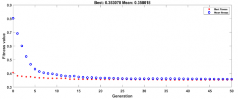
Figure 2. Fitness value for FLC obtained by GA
Figure 3. Fitness value for FOPID obtained by GA
Figure 4. Flow chart GA
GA is used to obtain the FOPID and FL controller parameters with ITAE as the objective function. Genetic algorithms have been used as a tool to obtain the gains of FLC and FOPID controllers in closed loop without improving it.
ITAE is the objective function that can used to validate the response the controller during the optimization process to get the pest solution. Overshoot, rising time, and settling time optimization are all combined in this function [18, 19]
The objective function is represented by:
$\operatorname{ITAE}=\int_0^T t|e(t)| d t$ (2)
The cost function to be minimized has been chosen as the integral of time weighted absolute error (ITAE). For better ride comfort of the car, the tournament selection approach was chosen because it provides a better selection than roulette selection. Compared to roulette wheel selection, tournament selection converges faster. The shorter the time the algorithm needs to solve a problem, the faster its rate of convergence [20].
The following is the search space for input-output functions and scaling factors for FLC: e $\in$ [1:18], ec $\in$ [1:18].
For FOPID: Kp $\in$ [0.1:5], Ki $\in$ [0.1:5], Kd $\in$ [0.1:5], α, $\in$ [0:1]. Determining the search space for the controllers by the experience of the designers and by multiple attempts to reach the specified space. To make sure that each iteration of the search is in the direction of the gradient descent, the two Figures 2, 3 show each iteration of the search.
The simulation conditions must be set before beginning to model and analyze the vehicle's oscillation. Because of the nonlinear quarter car, air suspension model interconnected with the hydraulic actuator established above, three types of controllers are applied to make a comparison, which are the sliding mode controller, FOPID, and FLC. Simulations of several controllers in the MATLAB/Simulink environment were conducted to validate the electiveness of the controller proposed. From the Figure 3 represents the block diagram of FLC active pneumatic suspension system for a 3-DOF suspension system with hydraulic actuator. Two inputs error (e) and error of change (ec) with one output (u) which has the desired force of the actuator, the output of FLC is the input to actuator and the rule-base has been implemented. The acceleration of sprung mass (error e) and the derivative of acceleration of sprung mass (change of error ec) are employed as inputs and control of output (input to model). For the control FOPID the input error is the acceleration and the output is applied on the hydraulic actuator as the Figure 5.
Figure 5. The GAO-controller schematic
In this section, the suspension travel, wheel deflection, vertical displacement, and car body acceleration for quarter cars will all be measured in the root square mean (RMS) values.
4.1 Road disturbance
One of the suspension system's functions is to reduce the impact of road irregularities on the vehicle's body. Random road surface irregularity was chosen as the excitation source waveform for car suspension. The random road profile is created by filtering white noise with the following road roughness mathematical model based on ISO-road of level B with a speed of 20 m/s as the equation below.
$\dot{r}(t)+2 \pi f_0 r(t)=2 \pi n_0 \sqrt{G_q\left(n_0\right) v(t)} w(t)$ (3)
where:
$G_q$ (no) is the coefficient of road roughness; $n_0$ is a reference spatial frequency which is equal to 0.1m−1; $f_0$ with a value of is a minimum boundary frequency of 0.0628 Hz; u(t) is the speed in m/s; w(t) is a white noise signal.
Anti-disturbance capability with regard to road input is an essential metric to consider when assessing a suspension system. The simulation is carried out using the parameters of the vehicle and actuator [16] as shown in Table 2.
Table 2. Specific parameters of the quarter vehicle and actuator
|
Symbol |
Description |
Value |
|
Ms |
The sprung mass |
400 kg |
|
Mus |
An unsprung mass |
40 kg |
|
C |
The damper coefficient |
3,000 Ns/m |
|
Kt |
Tire coefficient |
180,000 N/m |
|
Ae |
Effective area of the airbag |
0.002 m2 |
|
AS |
Cross section of a connecting pipe |
3*10-4 m2 |
|
Ls |
Length of connecting pipe |
2 m |
|
VRO |
Initial volumes of the reservoir |
$0.004$ m3 |
|
VBO |
The bag's initial volume |
$0.008$ m3 |
|
βe |
effective bulk modulus of hydraulic system |
1s-1 |
|
σ |
Actuator coefficient |
4.515*1013N/m |
|
τ |
Time coefficient |
1/30s |
|
Kc |
Servo valve gain |
0.001m/V |
|
Ap |
Piston cross section |
3.35*10-4m2 |
|
Ps |
Pressure supply |
10.3425*106pa |
|
po |
Initial absolute pneumatic spring pressure |
4*105N/m2 |
In the next sections, the results of the simulation when the different parameters for the air suspension are changed will be shown and their effects will be talked about.
For a more thorough examination, the parameters of the air spring with auxiliary chamber with controller are optimized to make the performance analyses of the active pneumatic suspension system better. The controllers with pneumatic systems have been operated over time and their outputs, i.e., indicators, have been in comparison time domain. It can be seen that it turns out that each controller possesses certain indicators through the Table 3.
Figures 7 and 8 show performance analysis of fuzzy logic control (FLC) pneumatic suspension. Figures 6 and 7 show performance analysis of sliding mode control (FOPID) pneumatic suspension.
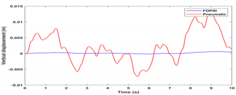
The displacement attenuation of the sprung mass with the proposed controllers is dramatically improved in Figures 7(a) and 9(a), with the maximum vertical displacement being 0.32mm for FLC and 0.28mm for FOPID.
Figure 6. Road input profile ISO class B
(a)
(b)
(c)
Figure 7. (a) Vertical displacement of sprung mass, (b) Acceleration of sprung mass, and (c) Velocity of sprung mass
Table 3. Optimization results of controllers-reduction % with pneumatic in RMS
|
Parameters |
Pneumatic |
Optimal FLC |
Reduction % |
Optimal FOPID |
Reduction % |
|
Vertical displacement (m) |
3.947e-3 |
2.15e-4 |
94.5% |
1.241-4 |
96.8% |
|
Acceleration (m/s^2) |
1.611e-1 |
2.411e-3 |
98.5% |
3.642e-3 |
97.7% |
|
Velocity of sprung mass(m/s) |
1.447e-2 |
2.232e-4 |
98.5% |
2.354e-4 |
98.4% |
|
Road holding (m) |
4.126e-3 4.126e-4 |
4.559e-4 4.009e-4 |
89% 3% |
3.502e-4 |
91% 12% |
(a)
(b)
(c)
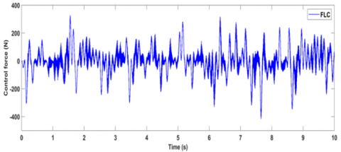
Figure 8. (a) Road holding, (b) Suspension travel, and (c) Control force of the actuator
(a)
(b)
(c)
Figure 9. (a) The displacement of sprung body, (b) Acceleration of sprung body, and (c) Velocity of sprung body
Body acceleration in RMS is also significantly different when the active air suspension is used, which improves ride comfort compared to the pneumatic system by 98.5% and 97.7% for FLC and FOPIDC, respectively, as in Figures 7(b) and 9(b). In Figures 4(c) and 6(c), the maximum velocity of sprung mass is 0.78 mm/s for FLC and 0.7 mm/s for FOPIDC. Figures 8(a) and 10(a) illustrate the road holding for vehicles improved to 89% (FLC) and 91% (FOPIDC) compared to the pneumatic system. The effect of this improvement can be quantitatively evaluated by obtaining the stability and comfort of the passengers when the vehicle travels on the rough road described earlier.
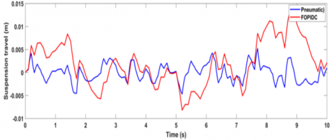
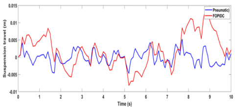
Figures 8(b) and 10(b) show that the suspension travel for controllers is greater than the suspension travel for pneumatic systems due to the time difference between the works of the system's parts. In addition, Figures 8(c) and 10(c) show the control force reaching in root-mean-square in ten seconds for the roughness road about a value of 80.64N for fuzzy logic control and about a value of 94.53N for FOPID control. This means that the rate of energy consumption is lower for the controller FL. The effect of this improvement can be quantitatively evaluated by obtaining the stability and comfort of the passengers when the vehicle travels on the rough road which described earlier. The improvement compared to other methods is considered better because the passenger does not feel the rough road, but the other deflections will be between the sprung mass and the unsprung mass. To compare this method with the rest of the methods, we find a clear improvement in reducing the vertical displacement and the vertical acceleration of the sprung mass clearly [21].
(a)
(b)
(c)
Figure 10. (a) Road holding, (b) Suspension travel, and (c) Control force of the actuator
(a)
(b)
(c)
(d)
(e)
Figure 11. (a) Comparison of body acceleration with velocity, (b) Comparison of road holding with vehicle velocity, (c) Comparison of velocity of sprung mass with velocity of vehicle, (d) Comparison of vertical displacement of with velocity of vehicle, and (e) Comparison of suspension travel sprung mass with velocity of vehicle
In Table 3, the results of how well the proposed controller's strategy worked are shown.
4.2 Vehicle speed difference
The road disturbance shown in Figure 6 is used, and the vehicle speed will be changed for each control system, i.e., the vehicle speed on the road will be at a different speed of (5-72) km/h. Figure 11 shows Performance analysis of indicators active air suspension of with speed of the vehicle.
An active suspension performs after inserting an actuator into the air suspension to achieve the desired control force calculated by the control unit. A numerical simulation of the active air suspension system analyzed the performance of the control strategy with the vehicle speed through some indicators: body acceleration, road holding, suspension travel, vertical displacement, and mass spread speed as evaluation indicators, and the control performance was analyzed. From Figure 11(a), the active air suspension system uses optimal controllers; fuzzy control gives better ride comfort than the active air suspension system with optimal FOPID control. When the vehicle speed increases, the stability of the vehicle decreases very slightly and imperceptibly, and this is observed starting from a speed of 5 km/h until it reaches a speed of 72 km/h (Figure 11(b)). Figure 11(c) shows that there is a convergence between the two controllers, FL and FOPID, in the increasing sprung mass velocity as the vehicle speed increases. In the illustration (Figure 11(d)), it is shown that the vertical displacement of the body increases slowly and gradually with the increase in the vehicle speed for the two controllers. The above Figure 11(e) shows that there is a clear convergence of the controllers for the distance between sprung and unsprung mass as the speed of the vehicle increases on a rough road.
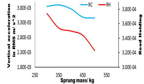
4.3 Different vehicle mass
(a)
(b)
Figure 12. Performance analysis of optimal FOPID air suspension for RC and RH with mass of vehicle (a), and (b) Performance analysis of optimal FLC air suspension for RH and RC with mass of vehicle
The mass of the springs for the proposed model varies from 300-500 kg, and the aim of this paper is to make the ride more comfortable and reduce the discrepancy between them as much as possible. Figure 12 (a, b) shows that if the sprung mass increases, both indicators improve, and in particular, the controller FL shows a significant improvement compared to the FOPID controller.
The Figures 12(a) and 12(b) represents a study of the behavior of increasing the mass with the passenger comfort and the stability of the vehicle for this type of suspension system. When compared this method with the passive suspension, because in the passive suspension system, the comfort of the passenger and the stability of the wheel clear conflict [22].
Characterization of the displacement and acceleration values of the sprung mass in the vehicle's suspension system, which play a part in controlling and dampening vibrations brought on by the impact of the road. The mathematical modeling, control and Genetic algorithm optimization of an active nonlinear (3DOF) quarter car suspension system are presented in this study. The air suspension with a hydraulic actuator system provides a qualitative improvement in vehicle performance and improved ride comfort compared to traditional air suspension systems. The fuzzy logic control simulation results have better performance in controlling and isolating the output vibration from the road compared to using the FOPID controller for air suspension and for the same calculation time. GA to get better values carried out the optimization of FLC and FOPIDC tuning parameters, this strategy is extremely reliant on the model's accuracy. As a result, the FLC controller is the best in its class in terms of decreasing passenger body vibration and thereby improving ride quality, findings demonstrate that when a pneumatic suspension integrates with a hydraulic actuator system, the sprung mass's displacement and acceleration are significantly lower than the tradition suspension pneumatic system.
|
Fca |
Nonlinear damping force, N |
|
Fa |
Actuator force, N |
|
Fc |
Linear damping force, N |
|
Fvz |
Vertical viscous nonlinear force |
|
Fke |
Main spring force, N |
|
Fkv |
Auxiliary spring force, N |
|
FS |
Pneumatic force, N |
|
Fz |
Static force, N |
|
Zd |
Displacement desired |
|
r |
Bump of the road, m |
|
ms |
Sprung mass, kg |
|
mus |
Unsprung mass, kg |
|
ma |
Air mass, kg |
|
Zs |
Displacement of the sprung mass, m |
|
Zus |
Displacement of unsprung mass, m |
|
ωs |
Displacement of the air mass, m |
[1] Alonso, A., Gimenez, J. G., Nieto, J., Vinolas, J. (2010). Air suspension characterization and effectiveness of a variable area orifice. Vehicle System Dynamics, 48(S1): 271-286. https://doi.org/10.1080/00423111003731258
[2] Yin, Z.H., Khajepour, A., Cao, D.P., Ebrahimi, B., Guo, K.H. (2012). A new pneumatic suspension system with independent stiffness and ride height tuning capabilities. Vehicle System Dynamics, 50(12): 1735-1746. https://doi.org/10.1080/00423114.2012.660167
[3] Karimi Eskandary, P., Khajepour, A., Wong, A., Ansari, M. (2016). Analysis and optimization of air suspension system with independent height and stiffness tuning. International Journal of Automotive Technology, 17(5): 807-816. https://doi.org/10.1007/s12239-016-0079-9
[4] Abid, H.J., Chen, J., Nassar, A.A. (2015). Equivalent air spring suspension model for quarter-passive model of passenger vehicles. International Scholarly Research Notices, 2015: 974020. http://dx.doi.org/10.1155/2015/974020
[5] Gavriloski, V., Jovanova, J., Tasevski, G., Đidrov, M. (2014). Development of a new air spring dynamic model. FME Transactions, 42(4): 305-310. https://scindeks.ceon.rs/article.aspx?artid=1451-20921404305G.
[6] Moheyeldein, M.M., Abd-El-Tawwab, A.M., Abd El-gwwad, K.A., Salem, M.M.M. (2018). An analytical study of the performance indices of air spring suspensions over the passive suspension. Beni-Suef University Journal of Basic and Applied Sciences, 7(4): 525-534. https://doi.org/10.1016/j.bjbas.2018.06.004
[7] Zhu, H.J., Yang, J., Zhang, Y.Q., Feng, X.X., Ma, Z.Y. (2017). Nonlinear dynamic model of air spring with a damper for vehicle ride comfort. Nonlinear Dynamics, 89(2): 1545-1568. https://doi.org/10.1007/s11071-017-3535-9
[8] Nieto, A.J., Morales, A.L., Chicharro, J.M., Pintado, P. (2010). Unbalanced machinery vibration isolation with a semi-active pneumatic suspension. Journal of Sound and Vibration, 329(1): 3-12. https://doi.org/10.1016/j.jsv.2009.09.001
[9] Al-Ghanim, A.M.H., Nassar, D.A. (2018). Modeling, simulation, and control of half car suspension system using Matlab/Simulink. International Journal of Science and Research (IJSR), 7(1): 351-362. https://doi.org/10.21275/ART20179298
[10] Sathishkumar, P., Jancirani, J., Dennie, J. (2014). Reduction of axis acceleration of quarter car suspension using pneumatic actuator and active force control technique. Journal of Vibroengineering, 16(3): 1416-1423. https://www.extrica.com/article/14805
[11] Shalabi, M.E., El-Hussieny, H., Abouelsoud, A.A., Elbab, A.M.F. (2019). Control of automotive air-spring suspension system using Z-number based fuzzy system. In 2019 IEEE International Conference on Robotics and Biomimetics (ROBIO), pp. 1306-1311. https://doi.org/10.1109/ROBIO49542.2019.8961492
[12] Anh, N.T. (2020). Control an active suspension system by using PID and LQR controller. International Journal of Mechanical and Production Engineering Research and Development, 10(3): 7003-12. https://doi.org/10.24247/ijmperdjun2020662
[13] Li, Z.X., Song, X.Y., Chen, X., Xue, H.T. (2021). Dynamic characteristics analysis of the hub direct drive-air suspension system from vertical and longitudinal directions. Shock and Vibration, 2021: 8891860. https://doi.org/10.1155/2021/8891860
[14] Gavriloski, V., Jovanova, J. (2010). Dynamic behaviour of an air spring element. Machines & Industrial Design Engineering, 4(5): 24-27. http://mech-ing.com/journal/Archive/2010/4-5/1.Mashini/75_gavriloski.mtm10.pdf.
[15] Lin, J., Lian, R.J., Huang, C.N., Sie, W.T. (2009). Enhanced fuzzy sliding mode controller for active suspension systems. Mechatronics, 19(7): 1178-1190. https://doi.org/10.1016/j.mechatronics.2009.03.009
[16] Tuan, A. (2021). Advance the stability of the vehicle by using the pneumatic suspension system integrated with hydraulic actuator. Latin American Journal of Solids and Structures. https://doi.org/10.1590/1679-78256621
[17] Berg, M. (1999). A three–dimensional air spring model with friction and orifice damping. Vehicle System Dynamics, 33(sup1): 528-539. https://doi.org/10.1080/00423114.1999.12063109
[18] Durairaj, U., Murugananthan, V., Mohd, N., Banupriya, B. (2019). Automation of hydraulic active suspension system using harmony search algorithm tuned FOPID. International Journal of Simulation: Systems, Science & Technology. https://doi.org/10.5013/IJSSST.a.19.06.01
[19] Tran, H.K., Chiou, J.S., Peng, S.T. (2016). Design genetic algorithm optimization education software based fuzzy controller for a tricopter fly path planning. Eurasia Journal of Mathematics, Science & Technology Education, 12(5): 1303-1312. https://doi.org/10.12973/eurasia.2016.1514a
[20] Zhong, J.H., Hu, X.M., Zhang, J., Gu, M. (2005). Comparison of performance between different selection strategies on simple genetic algorithms. In International Conference on Computational Intelligence for Modelling, Control and Automation and International Conference on Intelligent Agents, Web Technologies and Internet Commerce (CIMCA-IAWTIC'06), Vienna. https://doi.org/10.1109/CIMCA.2005.1631619
[21] Singh, D. (2018). Passenger body vibration control in active quarter car model using hybrid ANFIS PID controller. International Journal Intelligent Systems and Applications, 10(5): 51-60. https://doi.org/10.5815/ijisa.2018.05.06
[22] Phalke, T.P., Mitra, A.C. (2016). Analysis of Ride comfort and Road holding of Quarter car model by SIMULINK. 5th International Conference of Materials Processing and Characterization (ICMPC 2016), 4(2): 2425-2430. https://doi.org/10.1016/j.matpr.2017.02.093