Ghezail Abdi | Mohammed Amine Amraoui | Nassira Medjadji | Giulio Lorenzini* | Younes Menni
© 2022 IIETA. This article is published by IIETA and is licensed under the CC BY 4.0 license (http://creativecommons.org/licenses/by/4.0/).
OPEN ACCESS
This paper offers a computational and thermal analysis of a flat air solar collector with wings-shaped baffles. The finite volume approach was used to finish the study and solve the system of equations using the ANSYS FLUENT CFD engine. The sensor’s thermal simulation model is provided in the first part of this study; this is a three-dimensional model of a flat air solar collector. Close to the walls, the mesh is unstructured and refined. Dead zones and recirculation regions are eliminated in our concept due to the form of the baffles and their encasement. We came to the conclusion that turbulence has a significant impact in in the zones around the baffles. The rise in Reynolds number is connected to an increase in the Nusselt number, a drop in the values of friction factor, and a reduction in the Stanton number.
fluid mechanics measurement, thermal measurement, solar energy collector, three-dimensional simulation, turbulence
In the air solar energy collector, it is interesting to make changes for higher performance or thermal efficiency due to insufficient heat exchange between the airflow and the absorber surface. The shape of a solar collector, which is used to convert solar energy into thermal energy, influences its performance as well as the technology used and how heat loss on the collection surface is controlled.
Many studies on the development of air stream heat transfer for flat air solar collectors have been conducted. The study of a solar sensor with seven perforations intended to dry the Gelidium sesquipedale in Morocco is presented in El-Abidi’s article [1]. They used the finite element method to create the digital simulation, and the subject of this work is the demining the drying time. They have given the parameters that give a good thermal efficiency of the flat air solar collector.
Oyinlola and Shire [2] investigated a solar sensor with micro-channels for use in building heating, doing a numerical simulation with the code ANSYS CFX, as well as an experimental and numerical research to improve the operational parameters. Menasria et al. [3] provides a study of a flat air solar collector with inclination baffles at the top, using FLUENT for numerical simulation and RNG k-ε for the model. They found that placing the baffles at the bottom of the sensor allows for improved heat transmission.
Shandal et al. [4] conducted research on a flat air solar collector with rectangular baffles that served a dual purpose of heating air and water, and they utilized the computer program COMSOL Multiphysics 5.4 to generate numerical finding. They came to the conclusion that lowering the air sped raises the output temperature; if the water arrives at a high temperature, the efficiency falls; in other cases, the efficiency rises with a high mass flow. Korti et al. [5] produced a porous material in the lower channel section of a double pass solar energy collector during his research. They performed a validation between their model and experimental analysis, and then they presented data on Nusselt in mass flow function, velocity, and temperature field for several model studies.
Korobka et al. [6] have created a novel solar air collector design for a solar fruit drier that has double-glazing and a selective surface composed of a thin metal substrate on the bottom with input and outlet holes. It has been determined that for a double-glazed substrate, glass with a heat reflecting coating of solid glass in type k with a coefficient of radiation, ε of 0.1 to 0.15 is required. This produces the broadest spectrum of direct sunlight possible, which irradiates the absorbent plate’s surface and decreases the scattered component of the radiation, increasing the collector’s effectiveness.
Oudjedi et al. [7] present a study of a solar air collector, which demonstrates that, under the assumption of quasi-stationary operation, the heat balance equations of the air collector’s components cascade into an ordinary differential equation, which alone governs the sensor’s thermal behavior. The use of a differential equation like this considerably simplifies the study of the sensor’s sensitivity factors. The results of the research show that while the heat transfer fluid’s output temperature does not increase considerably as its intake temperature rises, the insulator’s daily thermal efficiency falls linearly as the inlet fluid temperature rises. When the speed of the humid air rises, the heat transfer fluid’s output temperature drops. By increasing the speed of the humid air, the daily thermal efficiency of the solar air collector improves fast. Furthermore, when the height of the fluid flow channel is raised, the temperature output of the heat transfer fluid, as well as the daily thermal efficiency of the collector, decreases constantly.
Rodonb and Volpes [8] conducted research on a planar vertical air solar collector for building heating. They displayed the temperature distribution based on the solar collector’s length. They presented a method for optimizing the shape and materials used in the production of flat air solar collectors. Amraoui et al. [9] conducted research on a flat air solar collector with circular baffles to increase turbulence in the solar collector’s fluid vein. They computed numerical findings in the fields of speed, temperature, and turbulence using the ANSYS computational package. The impact of circular baffles on heat transmission between the absorber and the coolant is demonstrated in this study. Kamali and Binesh [10] illustrated the heat transmission coefficient dispersion between a pair of vortex generators. The findings revealed that the rib shape has a significant impact on the inter-rib distribution of the heat transfer coefficient, with trapezoidal ribs with decreasing height in the flow direction providing greater heat transfer enhancement and pressure drop than other forms. Nanan et al. [11] studied the turbulent convective characteristics in a tube with twisted baffles both experimentally and numerically. The twisted baffles had the maximum thermal enhancement of 1.7 when the pitch ratio was the smallest (P/D = 1.0) and the Reynolds number was the lowest (Re = 6,000).
Boonloi and Jedsadaratanachai [12] investigated numerically performance enhancement in a square duct with discrete combination baffles, which incorporate a V-baffles with a V-orifice. According to their research, depending on the blockage ratio, V-tip orientations, and Reynolds number, the improved heat transfer rate is about 2.8-6 times greater than the smooth duct. Wang et al. [13] examined the flow field within a rectangular exchanger with baffles both computationally and empirically. In a staggered configuration, several various shaped baffles, such as round, drop and elliptical-shaped, were verified. The heat transfer improvement of the drop baffles was smaller than that of the circular baffles, according to their research. Drop baffles are a viable alternative to circular baffles in terms of particular performance characteristics.
The V-baffles in an upstream situation creates high impinging areas on the duct surfaces, which results in increased heat transmission rates in jet impinging zones, according to Fawaz et al. [14]. Tamna et al. [15] did a numerical simulation to explore heat transmission and flow field characteristics in an exchanger with 45° V-baffles to shed light on the heat transfer process, and the numerical results are in excellent agreement with experimental results. Moreover, a detailed study was conducted by Menni et al. [16-18] on the V-baffles for different orientations and locations. The outlet oriented baffles with the last space between them demonstrated an improvement in efficacy in the research.
It is well understood that creating longitudinal vortices in a flow improves heat transfer. Segmental baffles may be used to produce these vortices as well [19, 20]. Many physical phenomena were observed in these investigations, including turbulence and the development of reverse flows. Others models of obstacles, as shown in Table 1, such as segmental porous [21], trefoil-hole, helical and segmental [22], sextant/trisection helical [23], double-segmental [24], cut-segmental silica-gel [25], overlapped helical [26], middle-overlapped helical [27], segmental perforated [28], flexible porous elastic [29], and porous-blocked [30] are used to verify the baffles’ effectiveness.
The lack of a turbulence promoter in the fluid stream results in a low yield for flat solar air collectors, promoting researchers to look for other ways to improve the sensor’s performance. As a result, the second type of collector was born, fitted with baffles as turbulence promoters, promoting better heat transfer between the absorber and heat transfer fluid.
Table 1. The most recent channels with a variety of baffles
|
Author (s) |
Investigated baffles |
|
Kamali and Binesh [10] |
Trapezoidal, triangular, square, and quilateral |
|
Nanan et al. [11] |
Twisted |
|
Boonloi et al. [12] |
Discrete |
|
Wang et al. [13] |
Drop |
|
Fawaz et al. [14] |
In-line 'V' |
|
Tamna et al. [15] |
Multiple 'V' |
|
Menni et al. [16] |
'V' in various situations |
|
Menni et al. [17] |
Downstream 'V' |
|
Menni et al. [18] |
'V' with different separations |
|
Ji et al. [19] |
Segmental |
|
Kunwer et al. [20] |
Segmental and helical |
|
Abbasi et al. [21] |
Segmental porous |
|
El Maakoul et al. [22] |
Trefoil-hole, helical and segmental |
|
Chen et al. [23] |
Sextant/trisection helical |
|
Milcheva et al. [24] |
Double-segmental |
|
Kabeel et al. [25] |
Cut-segmental silica-gel |
|
Zhang et al. [26] |
Overlapped helical |
|
Zhang et al. [27] |
Middle-overlapped helical |
|
Salem et al. [28] |
Segmental perforated |
|
Cho et al. [29] |
Flexible porous elastic |
|
Chen et al. [29] |
Porous-blocked |
Therefore, while the use of baffles in a collector’s dynamic vein remains an effective means of improving its performance, the disadvantage of baffles is the appearance of significant dead zones and recirculation zones. In our study, we created a model of baffles in the shape of wings that we positioned in the air stream of a flat solar air collector to eliminate dead zones and recirculation.
2.1 Three-dimensional winged solar collector
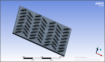
An investigation of a flat solar air collector with wing- baffles is carried out. It’s a three-dimensional study with a turbulent flow; using the ANSYS CFD calculation code. For turbulence, the k-ɛ model is employed. The solar collector has a length of 0.9 m, a width of 0.5 m, a height of 0.025 m, and a length of 0.13 m for the baffles, as illustrated in Figure 1.
Figure 1. Flat solar air collector with wing-shaped baffles
2.2 Modelling and simulation
The mass and momentum conservation equations are presented as follows:
$\nabla \cdot(\rho \vec{v})=0$ (1)
$\nabla \cdot(\rho \vec{v} \vec{v})=-\nabla p+\nabla\left(\begin{array}{c}= \\ \tau\end{array}\right)+\rho \vec{g}$ (2)
with
$\frac{=}{\tau}=\mu\left[(\nabla \vec{v}+\nabla \vec{v} T)-\frac{2}{3} \nabla \vec{v} I\right]$ (3)
The energy conservation equation is presented as follows:
$\nabla .(\vec{v}(\rho E+p))=\nabla .\left(k_{e f f} . \nabla T-\sum_{j} h_{j} . \vec{J}_{j}+\left(\overline{\overline{{{\tau}}}}_{\text {eff }} . \vec{v}\right)\right)$ (4)
and
$k_{e f f}=k+\frac{C_{p} \mu_{t}}{\operatorname{Pr}_{t}}$ (5)
The turbulent Prandtl number, Prt, has a default value of 0.85.
$E=h-\frac{p}{\rho}+\frac{v^{2}}{2}$ (6)
$h=\sum_{j} Y_{j} h_{j}+\frac{p}{\rho}$ (7)
$h_{j}=\int_{T_{\text {ref }}}^{T} C_{p} \cdot j \cdot d T$ (8)
where, Tref = 298.15 K. The following transport equations provide the turbulent kinetic energy, k, and its turbulent eddy dissipation, ε,
$\frac{\partial}{\partial x_{i}}\left(\rho k u_{i}\right)=\frac{\partial}{\partial x_{j}}\left[\left(\mu+\frac{\mu_{t}}{\sigma_{k}}\right) \frac{\partial k}{\partial x_{j}}\right]+G_{k}-\rho \varepsilon$ (9)
and
$\frac{\partial}{\partial x_{i}}\left(\rho \varepsilon u_{i}\right)=\frac{\partial}{\partial x_{j}}\left[\left(\mu+\frac{\mu_{t}}{\sigma_{\varepsilon}}\right) \frac{\partial \varepsilon}{\partial x_{j}}\right]+C_{1 \varepsilon} \cdot \frac{\varepsilon}{k} G_{k}-C_{2 \varepsilon} \rho \cdot \frac{\varepsilon^{2}}{k}$ (10)
The turbulent viscosity, μt, is calculated as follows:
$\mu_{t}=\rho \cdot C_{\mu} \frac{k^{2}}{\varepsilon}$ (11)
where, σk, σε, C1ε, C2ε, and Cμ are the k-ε model constants.
The ANSYS FLUENT CFD model was utilized to complete the study and solve the system of equations using the finite volume technique. In the presence of various turbulence models, this approach has been applied in many investigations described in the literature, Table 2.
2.3 The boundary conditions
The air flow is 50 m3/hm2, which equals U0 = 0.02216 m/s per speed unit.
T0 = 300 K is the temperature at the flat solar air collector’s input;
k = 0.005 × U02 = 2.456 × 10⁻⁶ m2/s2 is the turbulent kinetic energy at the flat solar air collector’s input;
The energy dissipation at the flat solar air collector’s input is ε = 0.1 × k2 = 6.03 × 10⁻¹³ m2/s3;
Tabs = 380 K is the temperature of the absorber;
Tiso = 340 K is the temperature of the insulation and the bottom obstacle; and
Ps = Patm is the outlet pressure.
Table 2. Studies based on the method of finite volumes
|
Author (s) |
Turbulence model |
|
Menasria et al. [3] |
RNG k-ε |
|
Amraoui et al. [9] |
Standard k-ε |
|
Kamali and Binesh [10] |
SST k-ω |
|
Nanan et al. [11] |
Realizable k-ε |
|
Boonloi et al. [12] |
Realizable k-ε |
|
Wang et al. [13] |
Standard k-ε |
|
Fawaz et al. [14] |
RNG k-ε |
|
Tamna et al. [15] |
RNG k-ε |
|
Menni et al. [16] |
Standard k-ε |
|
Menni et al. [17] |
Standard k-ε |
|
Menni et al. [18] |
Standard k-ε |
|
El Maakoul et al. [22] |
Realizable k-ε |
|
Chen et al. [23] |
RNG k-ε |
|
Milcheva et al. [24] |
SST k-ω |
|
Khetib et al. [31] |
Standard k-ε |
|
Wu et al. [32] |
RNG k-ε |
|
Abidi [33] |
Standard k-ε |
|
Keramat et al. [34] |
RNG k-ε |
|
Du et al. [35] |
Realizable k-ε |
|
Khetib et al. [36] |
Standard k-ε |
3.1 Mesh generation
For the spatial discretization of a continuous medium, we utilized an unstructured mesh, as well as a geometric modeling of a domain using finite and well-defined proportional components. A mesh’s goal is to simplify a system by using a model that represents the system and, perhaps, its surroundings, in order to simulate computations or create graphic representations. There are 22,596 elements and 122,606 nodes in this computational domain. Figure 2 shows this situation.
Figure 2. The three-dimensional mesh model used
3.2 Numerical validation
Then, as shown in Table 3, we compared our numerical data to Moummi’s experimental findings [37], and the results are almost identical [38].
Table 3. Compare simulated findings with published experimental data [37]
|
Air field [Q in m3/hm2] |
Present CFD |
Exp. data [37] |
|
|
Temperature [T in °C] |
|
|
23.71 |
69 |
68 |
|
37.58 |
65 |
63 |
|
42.79 |
65 |
63 |
|
58.97 |
62 |
58 |
|
64.76 |
59 |
56 |
|
69.96 |
54 |
52.3 |
|
74.01 |
54 |
51 |
|
76.32 |
53 |
50 |
|
79.79 |
53 |
50 |
3.3 Temperature distribution
Figure 3 shows the temperature field generated by a digital simulation using the CFX calculator code. We can see that the temperature near the absorber is very important; the fluid close to the absorber begins to heat up by convection, and this hot part mixes with the cold part thanks to the baffles in the form of the wings. The first row of baffles receives thermal energy from the air entering at 300 k, and this temperature rises as the baffles are displaced until the flat solar air collector exits.
Figure 3. The flat solar air collector’s temperature field
3.4 Vector distribution
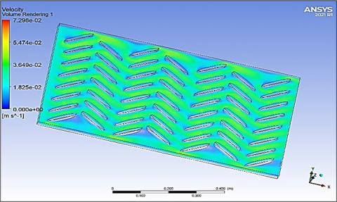
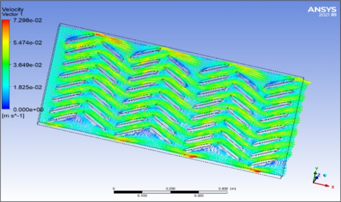
Figures 4 and 5 illustrate the speed distribution in the flat solar air collector; the speed is homogeneous until the first row of the baffles climbs to 70%; the airflow route is increased due to the slant of the baffles, allowing for greater heat transmission between the absorber and the air. The baffles’ design allows for improved air movement without producing dead zones and recirculation regions.
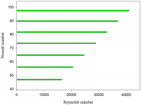
3.5 The Nusselt number versus Reynolds number
The goal of this discussion up to this point has been to demonstrate that in a plane solar air collector with wingers as a barrier, a simple analytical relationship for turbulent heat transfer may be found. A thorough examination of the Reynolds parallel between heat transmission and fluid friction is beyond the scope of this article, and the basic reasoning route selected here is intended to convey the general nature of physical processes.
The Dittus-Boelter equation may be used to get the Nusselt number as follows:
$N u=0.023 \operatorname{Re}^{4 / 5} \operatorname{Pr}^{0.4}$ (12)
where, Re ≥ 104. Figure 6 depicts a plot of the average Nusselt number (Nu) as a function of the Reynolds number between 16,500 and 41,000. We can see that as the flow rate rises, the Nu increases as well.
Figure 4. The flat solar air collector’s velocity field
Figure 5. The flat solar air collector’s velocity vector
Figure 6. The Nusselt number changes with Re values
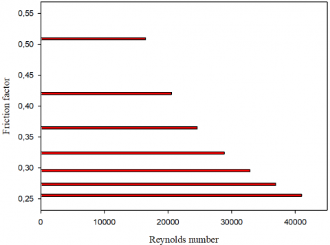
3.6 The friction factor versus Reynolds number
Petukhov created a smooth surface finish correlation that covers a wide range of Reynolds numbers and is expressed as the friction facto:
$f=\left(0.79 \ln \mathrm{Re}_{D}-1.64\right)^{-2}$ (13)
where, the Re is ranged from 3,000 to 5 × 10⁶. Figure 7 displays a curve that demonstrates how the friction factor decreases as the Reynolds number rises.
Figure 7. The friction factor changes with Reynolds values
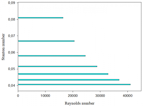
3.7 The Stanton number versus Reynolds number
Due to Pr ≈ 1 assumption, the derivation of the relationship for turbulent heat transport in channels with no obstacles is quite limited. For the flat plate problem, the heat transfer-fluid-friction analogy of the link between fluid friction and heat transmission revealed a dependency of the Prandtl number of Pr2/3 and, as it turns out. For turbulent tube flow, this dependence is sufficient. The following equation is used to determine the Stanton number:
St. $\operatorname{Pr}^{2 / 3}=\frac{f}{8}$ (14)
Figure 8. The Stanton number changes with Re values
Figure 8 shows the Stanton number as a function of the Reynolds number, and we can notice a decrease in the Stanton values as the flow rate improves.
The researchers proposed several solutions to improve the efficiency of flat solar air collectors, including adding baffles to increase the fluid flow path and increase heat transfer between the absorber and the heat transport fluid; however, the disadvantage of these obstacles is the creation of dead zones and recirculation regions. In the present research, we ran a numerical simulation of a flat solar air collector with wings-shaped baffles; this shape of the baffles, as well as their encasement in our model, eliminates the dead zones and recirculation regions, and we found that turbulence has a significant impact in the zones near the baffles.
[1] El-abidi, A., Yadir, S., Chanaa, F., Benhmida, M., Amiry, H., Ezzaki, H., Bousseta, H. (2018). Modeling and simulation of a modified solar air heater destined to drying the Gelidium Sesquipedale. International Journal of Renewable Energy Research, 8(4): 2003-2013.
[2] Oyinlola, M.A., Shire, G.S.F. (2019). Characterising micro-channel absorber plates for building integrated solar thermal collectors. Building Services Engineering Research and Technology, 40(1): 13-29. https://doi.org/10.1177/0143624418783173
[3] Menasria, F., Zedairia, M., Moummi, A. (2017). Numerical study of thermohydraulic performance of solar air heater duct equipped with novel continuous rectangular baffles with high aspect ratio. Energy, 133: 593-608. https://doi.org/10.1016/j.energy.2017.05.002
[4] Shandal, J., Abed, Q.A., Al-Shamkhee, D.M. (2020). Simulation analysis of thermal performance of the solar air/water collector by using computational fluid dynamics. In E3S Web of Conferences, 180: 02015. https://doi.org/10.1051/e3sconf/202018002015
[5] Korti, A.I.N. (2015). Numerical 3-D heat flow simulations on double-pass solar collector with and without porous media. Journal of Thermal Engineering, 1(1): 10-23. https://doi.org/10.18186/jte.86295
[6] Korobka, S., Babych, M., Krygul, R., Zdobytskyj, A. (2018). Substantiation of parameters and operational modes of air solar collector. Восточно-Европейский журнал передовых технологий, 3(8): 16-28. https://doi.org/10.15587/1729-4061.2018.132090
[7] Oudjedi, S., Boubghal, A., Chaouch, W.B., Chergui, T., Belhamri, A. (2008). Etude paramétrique d’un capteur solaire plan à air destiné au séchage (Partie: 2). Revue des Energies Renouvelables SMSTS, 8: 255-266.
[8] Rodonò, G., Volpes, R. (1998). Heat transfer calculation in a free convection air solar collector. Energy and Buildings, 27(1): 21-27. https://doi.org/10.1016/S0378-7788(97)00022-4
[9] Amraoui, M.A. (2020, December). Numerical study of an air flow in a flat plate air solar collector with circular obstacles. In International Conference in Artificial Intelligence in Renewable Energetic Systems, pp. 839-846. https://doi.org/10.1007/978-3-030-63846-7_81
[10] Kamali, R., Binesh, A.R. (2008). The importance of rib shape effects on the local heat transfer and flow friction characteristics of square ducts with ribbed internal surfaces. International Communications in Heat and Mass Transfer, 35(8): 1032-1040. https://doi.org/10.1016/j.icheatmasstransfer.2008.04.012
[11] Vickers, N.J. (2017). Animal communication: when I’m calling you, will you answer too? Current Biology, 27(14): R713-R715. https://doi.org/10.1016/j.cub.2017.05.064
[12] Boonloi, A., Jedsadaratanachai, W. (2016). Numerical investigation on turbulent forced convection and heat transfer characteristic in a square channel with discrete combined V-baffle and V-orifice. Case Studies in Thermal Engineering, 8: 226-235. https://doi.org/10.1016/j.csite.2016.07.003
[13] Wang, F., Zhang, J., Wang, S. (2012). Investigation on flow and heat transfer characteristics in rectangular channel with drop-shaped pin fins. Propulsion and Power Research, 1(1): 64-70. https://doi.org/10.1016/j.jppr.2012.10.003
[14] Fawaz, H.E., Badawy, M.T.S., Abd Rabbo, M.F., Elfeky, A. (2018). Numerical investigation of fully developed periodic turbulent flow in a square channel fitted with 45 in-line V-baffle turbulators pointing upstream. Alexandria Engineering Journal, 57(2): 633-642. http://dx.doi.org/10.1016/j.aej.2017.02.020
[15] Tamna, S., Skullong, S., Thianpong, C., Promvonge, P. (2014). Heat transfer behaviors in a solar air heater channel with multiple V-baffle vortex generators. Solar Energy, 110: 720-735. https://doi.org/10.1016/j.solener.2014.10.020
[16] Menni, Y., Chamkha, A., Zidani, C., Benyoucef, B. (2020). Baffle orientation and geometry effects on turbulent heat transfer of a constant property incompressible fluid flow inside a rectangular channel. International Journal of Numerical Methods for Heat & Fluid Flow, 30(6): 3027-3052. https://doi.org/10.1108/HFF-12-2018-0718
[17] Menni, Y., Azzi, A., Chamkha, A.J. (2019). Computational thermal analysis of turbulent forced-convection flow in an air channel with a flat rectangular fin and downstream v-shaped baffle. Heat Transfer Research, 50(18): 1781-1818. https://doi.org/10.1615/HeatTransRes.2019026143
[18] Menni, Y., Azzi, A., Chamkha, A.J., Harmand, S. (2019). Effect of wall-mounted V-baffle position in a turbulent flow through a channel: Analysis of best configuration for optimal heat transfer. International Journal of Numerical Methods for Heat & Fluid Flow, 29(10): 3908-3937. https://doi.org/10.1108/HFF-06-2018-0270
[19] Ji, J., Gao, R., Shi, B., Zhang, J., Li, F., Deng, X. (2022). Improved tube structure and segmental baffle to enhance heat transfer performance of elastic tube bundle heat exchanger. Applied Thermal Engineering, 200: 117703. https://doi.org/10.1016/j.applthermaleng.2021.117703
[20] Kunwer, R., Pandey, S., Bhurat, S.S. (2020). Comparison of selected shell and tube heat exchangers with segmental and helical baffles. Thermal Science and Engineering Progress, 20: 100712. https://doi.org/10.1016/j.tsep.2020.100712
[21] Abbasi, H.R., Sedeh, E.S., Pourrahmani, H., Mohammadi, M.H. (2020). Shape optimization of segmental porous baffles for enhanced thermo-hydraulic performance of shell-and-tube heat exchanger. Applied Thermal Engineering, 180: 115835. https://doi.org/10.1016/j.applthermaleng.2020.115835
[22] El Maakoul, A., Laknizi, A., Saadeddine, S., El Metoui, M., Zaite, A., Meziane, M., Abdellah, A.B. (2016). Numerical comparison of shell-side performance for shell and tube heat exchangers with trefoil-hole, helical and segmental baffles. Applied Thermal Engineering, 109: 175-185. https://doi.org/10.1016/j.applthermaleng.2016.08.067
[23] Chen, Y., Tang, H., Wu, J., Gu, H., Yang, S. (2019). Performance comparison of heat exchangers using sextant/trisection helical baffles and segmental ones. Chinese Journal of Chemical Engineering, 27(12): 2892-2899. https://doi.org/10.1016/j.cjche.2019.07.006
[24] Milcheva, I., Heberle, F., Brüggemann, D. (2017). Modeling and simulation of a shell-and-tube heat exchanger for Organic Rankine Cycle systems with double-segmental baffles by adapting the Bell-Delaware method. Applied Thermal Engineering, 126: 507-517.
https://doi.org/10.1016/j.applthermaleng.2017.07.020
[25] Kabeel, A.E., Abdelgaied, M. (2019). A new configuration of the desiccant dehumidifier with cut-segmental silica-gel baffles and water cooling for air conditioning coupled with HDH desalination system. International Journal of Refrigeration, 103: 155-162. https://doi.org/10.1016/j.ijrefrig.2019.04.009
[26] Zhang, J.F., Guo, S.L., Li, Z.Z., Wang, J.P., He, Y.L., Tao, W.Q. (2013). Experimental performance comparison of shell-and-tube oil coolers with overlapped helical baffles and segmental baffles. Applied Thermal Engineering, 58(1-2): 336-343. https://doi.org/10.1016/j.applthermaleng.2013.04.009
[27] Zhang, J.F., Li, B., Huang, W.J., Lei, Y.G., He, Y.L., Tao, W.Q. (2009). Experimental performance comparison of shell-side heat transfer for shell-and-tube heat exchangers with middle-overlapped helical baffles and segmental baffles. Chemical Engineering Science, 64(8): 1643-1653. https://doi.org/10.1016/j.ces.2008.12.018
[28] Salem, M.R., Althafeeri, M.K., Elshazly, K.M., Higazy, M.G., Abdrabbo, M.F. (2017). Experimental investigation on the thermal performance of a double pipe heat exchanger with segmental perforated baffles. International Journal of Thermal Sciences, 122: 39-52. https://doi.org/10.1016/j.ijthermalsci.2017.08.008
[29] Cho, I.H. (2021). Liquid sloshing in a swaying/rolling rectangular tank with a flexible porous elastic baffle. Marine Structures, 75: 102865. https://doi.org/10.1016/j.marstruc.2020.102865
[30] Chen, H., Guo, H., Ye, F., Ma, C.F. (2021). A numerical study of orientated-type flow channels with porous-blocked baffles of proton exchange membrane fuel cells. International Journal of Hydrogen Energy, 46(57): 29443-29458. https://doi.org/10.1016/j.ijhydene.2020.12.178
[31] Khetib, Y., Sedraoui, K., Melaibari, A.A., Alzaied, A., Alsulami, R., Sharifpur, M. (2021). Heat transfer and pressure drop in turbulent nanofluid flow in a pin-fin heat sink: Fin and nanoparticles shape effects. Case Studies in Thermal Engineering, 28: 101378. https://doi.org/10.1016/j.csite.2021.101378
[32] Wu, S.Y., Yan, R.R., Xiao, L. (2022). Numerically predicting the effect of fin on solar Trombe wall performance. Sustainable Energy Technologies and Assessments, 52: 102012. https://doi.org/10.1016/j.seta.2022.102012
[33] Abidi, A. (2021). Evaluation of thermal, electrical and overall efficiency of an air-cooled solar panel equipped with hexagonal pin-fins. Sustainable Energy Technologies and Assessments, 48: 101579. https://doi.org/10.1016/j.seta.2021.101579
[34] Keramat, F., Izadpanah, A.A. (2022). Thermo-hydraulic performance analysis of converging-diverging heat exchanger with inclined fins using computational fluid dynamics. Journal of the Taiwan Institute of Chemical Engineers, 132: 104119. https://doi.org/10.1016/j.jtice.2021.10.019
[35] Du, W., Luo, L., Wang, S., Zhang, X. (2018). Effect of the dimple location and rotating number on the heat transfer and flow structure in a pin finned channel. International Journal of Heat and Mass Transfer, 127: 111-129. https://doi.org/10.1016/j.ijheatmasstransfer.2018.08.045
[36] Khetib, Y., Sedraoui, K., Gari, A. (2021). Numerical study of the effects of pin geometry and configuration in micro-pin-fin heat sinks for turbulent flows. Case Studies in Thermal Engineering, 27: 101243. https://doi.org/10.1016/j.csite.2021.101243
[37] Moummi, A. (1994). Etude globale et locale du rôle de la géométrie dans l'optimisation des capteurs solaires plans à air. Doctoral dissertation, Valenciennes. https://www.theses.fr/1994VALE0021.
[38] Amraoui, M.A., Aliane, K. (2018). Three-dimensional analysis of air flow in a flat plate solar collector. Periodica Polytechnica Mechanical Engineering, 62(2): 126-135. https://doi.org/10.3311/PPme.11255