C.H. Pallavi* | G. Sreenivasulu
© 2021 IIETA. This article is published by IIETA and is licensed under the CC BY 4.0 license (http://creativecommons.org/licenses/by/4.0/).
OPEN ACCESS
For efficient underwater opto/acoustic communication, this research proposes the use of MIMO in conjunction with OFDM. OFDM (Orthogonal Frequency-Division Multiplexing) and MIMO (Multiple Input Multiple Output) systems may be widely used in wireless networks to provide high data transfer rates, resistance to multipath fading, and an increase in the channel's Spatial Multiplexing and Spatial Diversity Gain. Transmission speed can be increased by altering bandwidth or spectral efficiency (or both) in wireless data transmission systems. Systems that use Multi-Input Multi-Output (MIMO) technologies have the potential to improve spectral efficiency by employing several transmitters and receivers in tandem. To maximize spectrum efficiency and minimize inter-symbol interference, Orthogonal Frequency Division Multiplexing (OFDM) divides signals into a number of narrow band channels (ISI). In other words, combining the benefits of MIMO with OFDM will boost spectral efficiency while also increasing the link's dependability and spectral gain. MIMO and OFDM approaches are integrated in this research to increase opto-acoustic modem performance. MATLAB Simulink tool was used to design and simulate the proposed hybrid opto-acoustic modem with MIMO-OFDM for optical and acoustic (EM) signal transmission and reception. The simulation results verify the viability of the proposed method, and the measured bit-error rate (BER) for acoustic (EM) signal is 0.4958 and optical signal is 0.5101. The overall bandwidth of the system is from -150 MHz to +150 MHz.
bit-error rate (BER), inter symbol interference (ISI), multiple-input multiple-output (MIMO), orthogonal frequency-division multiplexing (OFDM), and opto-acoustic modem
The investigation of possible UWC techniques has a significant impact on wireless communications Changes in climate have been a worry for several decades [1]. The melting of the polar ice caps due to increased global warming produces an increase in the global water level. As a result, monitoring ocean environmental operations such as data gathering, water sampling, etc. has become increasingly important over time. Underwater Wireless Communication (UWC) aids in coastal security surveillance, particularly for military objectives and commercially for the research of underwater natural resources. It also aids in underwater mapping and discovery. UWC is increasingly being employed for research purposes, such as underwater navigation, disaster avoidance, and tsunami early detection and warning [2]. Underwater wireless communications (UWC) could be enabled through optical, acoustic, or electromagnetic (EM) carriers. The use of UWC techniques in an unknown aquatic medium is extremely difficult in comparison to terrestrial wireless communication [3]. Standard and reliability of data transmission, however, are water channel-dependent [4]. UWC's Quality of Service (QoS) is determined by the physicochemical qualities of water medium and the physical characteristics of optical, acoustic, and electromagnetic waves. The wireless network is heavily reliant on UWC's underwater applications, and thus has a significant effect on the wireless network. A communication network setup for underwater systems includes stationary sensor nodes on the seabed, floating unmanned underwater vehicle nodes (UUVs) or autonomous underwater vehicles (AUVs), signal reception processing towers, floating devices (buoys), submarines, ships, and onshore base stations [5]. EM waves in the radio frequency (RF) frequency range of 3Hz to 3kHz are capable of high data acquisition and transmission in shallow water over short distances and are usually dampened easily by seawater [6]. Acoustic waves, on the other hand, are affected by a variety of propagation parameters like as noise, external interference, water-surface geometrical expansion, attenuation, multipath effects, and Doppler spreading. However, underwater, optical waves are limited by absorption, scattering, and temperature variations due to their high bandwidth. Underwater optical communication (UWOC) is less investigated and more difficult to implement than underwater acoustic propagation [7]. Existing underwater wireless acoustic communication (UWAC) has poor bandwidth, latency, and multi-path propagation in an underwater medium, which restricts its performance. Data transmission in UWC has relied on optical, acoustic, and electromagnetic waves, each with advantages and disadvantages. As interest in deep-sea exploration and infrastructure deployment for asset monitoring grows, so does the need to send multimedia data between remote nodes underwater [8]. Because electromagnetic signals propagate poorly underwater, aural communication has taken off. With the minimal attenuation (signal reduction) of sound under water, acoustic communication is the most adaptable and extensively utilised underwater technology. However, the use of acoustic waves in shallow water can be harmed by temperature gradients, surface ambient noise, and multipath propagation due to reflection and refraction, as well as the much slower speed of acoustic propagation in water, about 1500 m/s (metres per second), when compared to optical waves. A realistic option for high-bandwidth communication across modest distances is optical communication (bits per second 10–150 Mbps) (10-100 meters). This communication range is critical for port inspections.
Maintenance of oil rigs, submarine-to-land links, and other such things. Many academics have worked extensively on optical terrestrial and space networks, but underwater communication research is very difficult due to the large.
There are numerous processes at work, ranging from those taking place in shallow water all the way down to the bottom of the sea. For short-range communication, current methods use acoustic underwater communication, which has a high transmission loss, Doppler effects, and multipath effects. All of these critical factors have contributed to the spatial and temporal variations, which have in turn contributed to the communication system's limited bandwidth. In terms of transmission distance, acoustic communication links can be categorised as short, medium, medium-long, long, or extremely long. Nevertheless, the underwater observatories require a communication link capable of supporting data rates up to tens of megabits per second (Mbps) [9].
UWAOC (underwater acoustic/optical communication) technology research is critical for military and civilian use. UWAOC is currently a key technology for underwater applications such as ocean surveillance and coastal development. These increasingly complicated underwater projects necessitate higher requirements for UWAOC; how to efficiently and reliably transmit the information through an underwater acoustic/optical channel is becoming increasingly difficult. High-speed UWAC systems using single carrier and multi-carrier modulation techniques are now being investigated extensively. Many methods have been investigated to deal with the multipath delay and Doppler effect in underwater acoustic channels. adaptive filter technology is highly successful at removing inter-symbol interference in single-carrier communication (ISI). Because of its high spectrum utilisation and low receiver design complexity (OFDM) for multi-carrier communications, orthogonal frequency division multiplexing (OFDM) has received a lot of attention in recent years [10].
Great data rate with high Quality of Service is the most difficult difficulty in underwater communication nowadays. Resource scarcity and signal propagation conditions like fading are generated by factors like multipath and interference, which vastly improve spectral efficiency, hence raising the reliability of the connection. These requirements are satisfied by MIMO technology, which boosts spectral efficiency by enhancing spatial multiplexing gain and improving link dependability via diversity antenna gain. Multi-carrier modulation (OFDM) and MIMO (multiple input multiple output) have been used to improve the performance of an underwater acoustic/optical communication system. Here's an idea for creating a new hybrid optical-acoustic modem for underwater communication (UWC) using the MIMO-OFDM technology. The following diagram depicts the structure of this document. Section 2 goes into detail on current underwater communication modems. Described in Section 3 is a MIMO-OFDM network architecture. Section 4 details the proposed hybrid opto-acoustic modem's MIMO-OFDM design. Section 5 discusses the simulation results of the proposed modem, and Section 6 concludes the paper by discussing its potential future applications.
(a) Acoustic modems: The deployment of UWAC (underwater wireless acoustic communication) is a difficult and ambitious task. When using RF or optical communication technologies, the propagation range is constrained by significant attenuation and water turbidity, making UWC a viable alternative communication medium for reaching out to great distances. Small, wide-bandwidth sound waves travel at about 1500 metres per second. Warm water allows acoustic waves to travel far more quickly than cold water, even underwater. There is a 4 m/s increase in sound wave speed for every 1℃ increase in water temperature. An exceptionally high increase in the speed of the sound wave (about 1.42 m/s) can be observed when the salinity rises by one practical salinity unit (PSU). Towards a greater depth of water, the frequency of acoustic waves increases by about 17 m/s per km as pressure and temperature rise.
Commercial Acoustic Modems:
The major specifications of the commercial acoustic modems are listed in the Table 1 [11-15].
(b) Optical Modems: High data rate, low latency, and covert communication between underwater vehicles or sensor nodes are all advantages of underwater optical communication. Late in the nineteenth century, the FSO (free space optical communication) technology was deployed in places where fibre optic links were not practical for long-distance transmission, the FSO method is utilised. This article summarises a lot of information about FSO [16, 17]. Many new and enhanced FSO system performance researches have been conducted and launched in recent years. Current predictions forecast FSO commercial use to more than double by the year 2018. Fast synchronous optical lines (FSO) are utilised for extremely high data transmission rates, whereas OWC terrestrial optical wireless communication (OWC) is available for up to 10 Gbps data transmission rates. I'm going to use numbers 10 and 12 [18-21]. Table 2 lists the major specifications for commercial optical modems.
The comparison of developed research modem’s is listed in the Table 3 [22].
Table 1. Major specifications of the commercial acoustic modems used [11-15]
|
Specifications |
AquaSeNT |
Benthos |
LinkQuest |
Develogic HAM |
EvoLogics WiSE |
SubNero |
|
Modulation Scheme |
OFDM |
MFSK/PSK |
DSSS/ Spread spectrum |
OFDM |
Sweep-spread carrier |
PSK- OFDM/FH-BFSK |
|
Freq. (kHz) |
14-10 |
9-14 |
26.77-44.62 |
6 |
18-78 |
24-27 |
|
Range / depth (km) |
7 |
2-6 |
1.2-1.5 |
23 |
3.5 or 1 |
3-5 |
|
Max. data rate (kbps) |
9 |
2.4/15.4 |
38.4 |
10 |
13.9/31.2 |
10-15 |
Table 2. Major specifications of the commercial optical modems used [18-21]
|
Specifications |
LUMA X |
MC100 |
Sonardyne’s BlueComm 100/200 |
Ifremer’s SiPM |
|
Speed/Latency |
High/Low |
High/Low |
High/Low |
High/Low |
|
Power (Watts) |
2-5 |
- |
10-30 |
- |
|
Range / depth (m) |
6000 |
3500 |
4000 |
17-60 |
|
Max. data rate (Mbps) |
10 |
95 |
1-5/10 |
3 |
|
Distance (m) |
50 |
10 |
1-15 |
17-60 |
Table 3. Comparison of research modems [22]
|
Reference |
Technology |
Frequency |
Modulation |
Range |
Data rate |
|
Anguita et al. [23] |
Acoustic Waves |
800 KHz |
BPSK |
1 m |
80 Kbps |
|
Li et al. [24] |
Acoustic Waves |
12 KHz |
MIMO-OFDM |
N/av |
24.36 Kbps |
|
Stojanovic [25] |
Acoustic Waves |
24 KHz |
QPSK |
2500 m |
30 Kbps |
|
Won et al. [26] |
Acoustic Waves |
70 KHz |
ASK |
70 m |
0.2 Kbps |
|
Frater et al. [22] |
Optical Waves |
N/av |
PPM |
1.8 m |
100 Kbps |
|
Baiden et al.[27] |
Optical Waves |
N/av |
N/av |
11 m |
9.69 Mbps |
|
Farr et al. [28] |
Optical Waves |
N/av |
N/av |
10m |
10 Mbps |
|
Cossu et al. [29] |
Optical Waves |
N/av |
N/av |
10m |
10 Mbps |
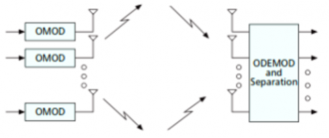
Multiple antennas are typically used to cancel out interference. Increased fundamental gain from numerous antennas at both the transmitter and receiver leads to more efficient use of the radio spectrum. Using spatial multiplexing increases capacity linearly with fewer transmitter and receiver antennas, as opposed to systems that use a single antenna on both the transmission and reception sides. Figure 1 shows a block diagram of a MIMO system. Figure 2 depicts a schematic depiction of the MIMO OFDM system, whereas Figure 3 depicts the modulation and demodulation of a single antenna OFDM system (see below). Figure 4 illustrates the process of adding the cyclic prefix.
This advantage can be easily obtained by simultaneously transmitting each individual data stream within the frequency bandwidth when the communication channel has strong scattering. The receiver uses the changes in spatial fingerprints created by the MIMO channel across the multiplexed data stream to separate the different types of signals. In doing so, you aid the system's capacity gain.
Figure 1. Block diagram of MIMO system model
Figure 2. Schematic representation of MIMO-OFDM system
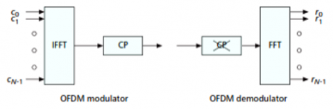
Figure 3. OFDM modulation and demodulation of single-antenna communication system
Figure 4. Addition of cyclic prefix
3.1 Basic OFDM transmitter and receiver
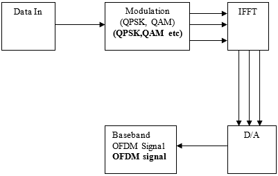
Figure 5. OFDM transmitter [30, 31]
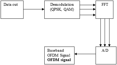
OFDM systems have more difficult synchronisation requirements than single-carrier systems, and Direct Sequence Spread Spectrum is more vulnerable to noise. They also have a low peak-to-power ratio. OFDM has a high spectral efficiency because its modulation method and carrier power may be changed separately for each carrier. One of the fundamental principles of OFDM is to divide a high-rate data stream into many lower-rate streams, each of which is simultaneously transmitted via multiple subcarriers [32]. Figure 5 illustrates the OFDM transmitter, whereas Figure 6 depicts the OFDM receiver.
Figure 6. OFDM receiver [30, 31]
3.2 Frequency signaling in MIMO-OFDM system
Spatial multiplexing [1] is the overall term for the various communication methods that are now in use. A capacity increase and a reduction in space time coding can simply be achieved using spatial multiplexing. There is also an increase in network trustworthiness due to increased diversity amongst nodes. For the most part, multi-antenna signaling methods combine diversity gain with spatial-multiplexing to maximise throughput. Pictured below are an example 4×4 system with four transmitting and four receiving antennas, while Picture 8 shows the basic layout of a MIMO system. Link connectivity and bandwidth can be improved with 4×4 or mxn MIMO systems. The Basic structure of a MIMO system and a 4x4 MIMO system is shown in Figure 7 and Figure 8.
Figure 7. Basic structure of a MIMO system
Figure 8. 4×4 MIMO system
Data stream is first separate into individual stream of data. the number of transmitting antennas represents the number of data streams. If the number of transmitting antennas and the number of receiving antennas are not equal then it means, the number of streaming data is found to be the smaller value of integers of m and n. The capacity of transmission can be increased is directly proportional to the number of streaming data.
3.3 Spatial multiplexing
The gain in spatial multiplexing or the number of communication channels can be obtained from the minimum number of transmitting and the receiving antennas with the perfect knowledge of channel by the receiving antennas. On the other side, the transmitter need not have to know the Channel State of Information. It is also proved by the researchers that the multipath propagation is highly beneficial in case of spatial multiplexing gain. The angles spread between the transmitting antennas tend to be increase by multipath propagation. This results in increase of rank of matrix of channel which results in increase of spatial multiplexing gain of the system. However, the complexity at the receiver side is significantly increased due to the increase need of separating the multipath components to equalize the number of MIMO channels.
3.4 Spatial multiplexing in MIMO-OFDM
Spatial multiplexing is done in a MIMO-OFDM system by broadcasting data streams as separate streams and sharing the transmitting power equitably among the toes and antennae. Despite the fact that OFDM eliminates the ISI, researchers have discovered that MIMO-OFDM has a significant computational complexity. As a result of the wide tone range (48-1728) and the requirement to execute spatial separation on each tone, this is the case.
3.5 Space-frequency coding in MIMO-OFDM
The aim of spatial multiplexing is to increase the spatial efficiency by the transmission of data streams individually. The basic idea behind this is the introduction of redundancy across the space and realizing the diversity gain at the transmitter side without CSI. In OFDM system with single antenna, the frequency diversity is performed by coding along with interleaving of tones across the channel. In MIMO channels, there are two diversity sources are available in frequency-selective fading. They are frequency and spatial diversity. The spatial diversity gain can be achieved by using the space time coding for coding across the space and frequency. By combining the forward-error-correcting code with interleaving across tone, throws the simple way to realize the space-frequency gain.
Figure 9. Multiple access in signal space (frequency) based on user collision
In most practical application systems, bit-interleaving code modulation is performed. The problem arises when the data symbols are spread by space-frequency codes across the space and frequency. This indicates that coding is done within a single OFDM symbol but not across the multiple OFDM symbols. Non-coherent MIMO-OFDM systems are shown more interest by the researchers as the maximum diversity of space and frequency can be achieved by considering ISI. Figure 9 represents the multiple access achieved based on the amount of collision in signaling space.
In this work, modem for opto-acoustic underwater communication using MIMO-OFDM system is proposed and the design is simulated for performance evaluation. The design of the proposed modem is discussed below. Figure 10 shows the proposed MIMO-OFDM based design of a novel hybrid opto-acoustic modem for underwater communication.
Figure 10. Proposed design of a novel hybrid opto-acoustic modem using MIMO-OFDM
4.1 Bernoulli binary generator
To produce random binary numbers, use the Bernoulli Binary Generator block, which makes use of a Bernoulli distribution. In order to get performance measures such as bit error rate, the random data bits created simulating digital communication systems are used. In the case of the Bernoulli distribution, the probability of zero is equal to p, while the probability of one is equal to 1-p. The mean and variance of the Bernoulli distribution are 1 and p, respectively (1-p). There can be any real number between [0, 1] in the Probability of zero parameter.
4.2 Variant sink
Variant Sink block is a toggle switch that activates one of its variation options at the output to pass the input. The block has a single input and one or more output ports. Every output port has its own variant control. Choose from the EM and Optical Paths.
4.3 Buffering and unbuffering
Whenever you use the Buffer block, frame-based processing is done. Data from each column of input is redistributed so that the output has a different frame size. Increasing the frame size of a signal buffer results in a slower frame rate on the output. Using this block, Mi-by-N input can be unbuffered into a 1-by-N output. Because the data is not buffered, each row of the matrix represents a separate time-sample in the output. In general, the rate at which the block receives inputs is slower than the rate at which the block generates outputs.
4.4 Input packing is vector/matrix concatenate block
Create a continuous output signal by concatenating signals of the same data type in the input. Depending on your needs, you can either use a vector or a multidimensional array. Whenever you're working in vector mode, you must use vectors, one-row [1xM] matrices, or one-column [Mx1] matrices as your input signals. It is a vector output if and only if all of the inputs are also vectors This function returns an empty matrix when any of the inputs are empty (e.g. a single row or single column). Use the 'Concatenate dimension' option in multidimensional mode to define the output dimension along which the input arrays should be concatenated. As an example, specifying 1 or 2 as the concatenation dimensions will combine the input arrays vertically and horizontally, respectively.
4.5 Variant source
When you use a Variant Source, you get a different signal from a different source. There can be no more than one input port active at a time during simulation because of the way the blocks connected to the input ports are organised. The simulation will remove blocks associated to inactive ports. The variant control determines which input port, if any, is active. One input port must be active, unless 'Allow zero active variant controls' is selected. Selects EM Signal or Optical Signal.
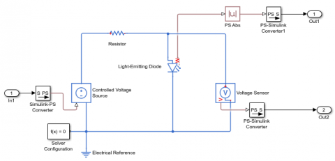
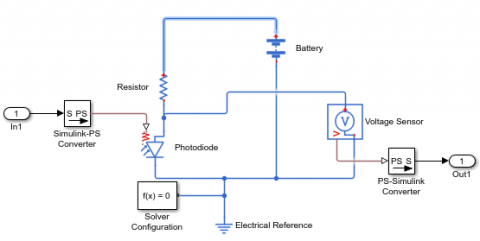
4.6 LED and photodiode
LED produces light and the signal that drives the LED changes the light intensity. Figure 11 shows the schematic representation of LED block of modem. Similarly, Figure 12 represents the photodiode block which converts light signal to appropriate electrical signals.
Figure 11. Schematic representation of LED block
Figure 12. Conversion of light into electrical signals
4.7 Convolution encoder
Using convolutionary coding, binary data can be encoded. Utilizing length constraints, a code generator (octal), and a feedback link, design a trellis with poly2trellis using the functions (octal). Use a poly2trellis command in the Trellis structure parameter to specify the encoder's constraint length, generator polynomials, and, if necessary, feedback connection polynomials. In order to employ an encoder with a constraint length of 7 and code generator polynomials of 171 and 133 (in octal numbers), set the Trellis structure parameter topoly2trellis, for example (7, [171 133], 171). The encoder's registers start out empty. If there are more index vectors than there are output ports, then more output ports are required. QAM Modulator with Rectangular Shapes With a constellation on a rectangular lattice, baseband block modulation employs M-ary quadrature amplitude modulation to create the modulation. The modulated signal is represented in baseband as the output. Scalar or column vector input signals are accepted by this block.
4.8 Space time diversity block encoder
Turn on or off the output signal's sampling mode. It uses an orthogonal space-time block coding to encode the message you feed it (OSTBC). For two transmit antennas, the OSTBC is rated at 1, for three and four transmit antennas, it is rated at 1/2, 3/4, or 1/1. There must be an N-column vector or a 2-dimensional matrix as the input. The encoder encodes each row separately for a complete matrix input. As an example, the number N must be more than two in order for the OSTBC to work with two transmit antennas or at rate half; the number N must be greater than three to work at rate three-fourth. Dimensional diversity block encoder, shown in Figure 13, is depicted in Figure 14.
4.9 MIMO-OFDM transmitter & receiver
Guard bands are used to perform Matrix Concatenation. An input signal's constituents can be reordered by selecting or rearranging them in a new order. To find the index of a certain element, open an input port or use this dialogue box. A successful IFFT Operation has been completed. In the reshaping block, the data is reshaped by transforming it from parallel to serial. Using Matrix Concatenation, four transmitter signals are combined into a single MIMO channel. Apply a multipath fading filter on the input signal before allowing it to pass through. This channel's gain and variance have been configured. AWGN distorts the input signal by adding white Gaussian noise. There are two types of input signals: real and complex. There is capability for multichannel processing in this block. When working with complex inputs, the variance values are shared equally across the real and imaginary parts of the input signal.
Figure 13. Space time block encoder
Figure 14. The simulation block diagram of MIMO-OFDM transmitter and receiver system
Variant Activating the sink block's variant choice at the output allows it to pass the input. Sink block is a toggle switch. With multiple output ports and a single input port, the block can be very flexible. An output port's variant control is assigned to every one of its outputs. Optionally selects between the Electrical Path and the Optical Path. There are four output ports on the Multiport Selector so it selects the four output ports for four transmitted signals all at the same time! When using an LED-Photodiode in an Optical Path, you're transmitting and receiving information via light. It's important to keep in mind that Matrix Concatenation works by combining four separate transmitted signals into a single signal. The EM or Optical Signal is selected by the Variant Source. Singleton dimensions are removed by squeezing a multi-dimensional input signal. It's called a singleton dimension since its maximum value is 1. A 2x1x3 signal, for instance, becomes a 2x3 signal. Signals in the 1-D and 2-D domains are unaltered by the filtering process. Conversion from serial to parallel; removal of the cyclic prefix; conversion from sample to frame; removal of the guard bands and DC; frame to sample conversion; concatenation. MIMO-OFDM transmitter and receiver simulation block diagram is shown in Figure 14.
Data is serialised and then parallelized using Reshape. Blocks can be reordered using the Remove Cyclic Prefix command. After the FFT Operation is completed, the sample-based signal is converted to frames using the Frame Conversion. One method of rearranging data is to remove the guard bands. the channel estimation and the space time block combining are combined by the Space Time Diversity Combiner. Frame to Sample Conversion follows DC removal as the initial step. Then Four sent signals are combined to form a single signal. The orthogonal space-time block coding structure combines the received signal and channel estimation inputs (OSTBC). A rate 1 OSTBC is appropriate when using only two transmit antennas, whereas rates 1/2 or 3/4 are more appropriate when using three or four transmit antennas, respectively. The received signal input must be a column vector or a full 2-D matrix for one receive antenna. Therefore, the channel estimate input needs to be a 3-D or a 2-dimensional matrix. Multiple receive antennas require a full 2-D or 3-D matrices for the received signal input. A 3-D or 4-dimensional matrix is required for the channel estimation input. The channel's synchronised signal is used. Extract data carriers execute parallel to serial conversion after selecting the data and removing the pilots.
QAM Demodulator in a Rectangular Shape The rectangular quadrature amplitude modulation method is used by baseband to demodulate the input signal. Baseband. When it comes to demodulation, the parameter for "Decision type" is set to "Hard decision." Data that has been convolutionally encoded can be decoded using the Viterbi method. Create a trellis using the poly2trellis function and the constraints of length, code generator (octal), and feedback connection (octal). Variant Activating the sink block's variant choice at the output allows it to pass the input. Sink block is a toggle switch. The block has one input and one or more output ports. A variant control is connected to each output port. Decides whether to use EM or optical path.
4.10 Error rate calculation
The error rate can be calculated by comparing the received data with the communicated data that was sent later. An error rate, number of errors found, and the total amount of symbols compared make up a three-element vector as block outputs. This vector can be transmitted to a workspace or to an output port, depending on your preferences. Both a scalar and a vector can be used as inputs; however, delays are defined in samples. There can only be scalars or column vectors passed into the "Tx" and "Rx" ports.
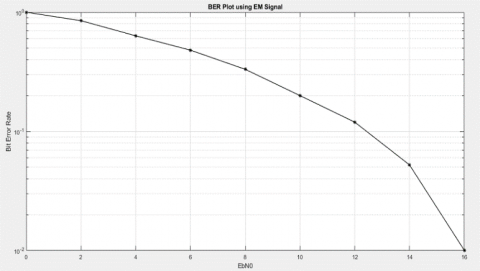
MATLAB-Simulink is used for the simulation of a Novel Hybrid Opto-Acoustic Modem using MIMO-OFDM transmitter and receiver for Underwater Wireless Communication. MATLAB R2018a version is used for the simulation. Figure 15 shows the BER plot for transmitting acoustic (EM) signal. Similarly, Figure 16 shows the BER plot for the optical signal. The total usage of System bandwidth is -150Hz to +150Hz. For the acoustic (EM) signal voltage of 1 (V=1), the BER achieve is 0.4958 and for V=2 (optical signal), the BER achieve is 0.5101. The maximum number of bits transferred is 1536.
Figure 15. BER plot using acoustic (EM) signal
Figure 16. BER plot using optical signal
The total system bandwidth usage for both optical and acoustic signals in underwater communication using the proposed hybrid opto-acoustic modem is shown in Figure 17.
Figure 17. System bandwidth usage for both optical and acoustic signals in underwater communication
In the recent past, underwater optical/acoustic modems have been developed and used for different underwater applications like oceanography data collection, military purposes, offshore mining and water quality monitoring etc. In this paper, a novel hybrid opto-acoustic modem based on MIMO-OFDM is proposed, which communicates both optical and acoustic signals. There are unique channels available for the transmission of acoustic source and optical source. EM signals are the input to acoustic channel and optical signals are the input to optical channel. Both the inputs are given to MIMO-OFDM, which is best suited modulation technique for the proposed hybrid modem. The novelty of the proposed hybrid modem over the existing modem is the introduction of MIMO-OFDM based system to perform the communication of both optical and acoustic signals through a single modem. The existing system modems use separate modems to communicate either acoustic or optical signals. The functionality of the proposed modem design is tested through simulation using MATLAB Simulink tool. In the proposed hybrid opto-acoustic modem, the measured bit-error rate (BER) for acoustic (EM) signal is 0.4958, and optical signal is 0.5101, respectively and the total system bandwidth is from -150MHz to +150MHz. Therefore, from analyzing the simulation results, the signal strength achieved for the both optical and acoustic (EM) signals are found as good and the performance of the proposed hybrid opto-acoustic modem has been improved in terms of BER, bandwidth and confirm the robustness of the proposed modem and the usage of bandwidth proves the efficiency of the proposed hybrid modem is better choice than the existing system modems. However, the future work can be implementing the proposed hybrid opto-acoustic modem on both underwater and terrestrial to achieve a successful high-speed long-distance communication application.
[1] Ali, M.F., Jayakody, D.N.K., Perera, T.D.P., Srinivasan, K., Sharma, A., Krikidis, I. (2019). Underwater communications: Recent advances. International Conference on Emerging Technologies of Information and Communications (ETIC), pp. 97-102.
[2] Uysal, M., Capsoni, C., Ghassemlooy, Z., Boucouvalas, A., Udvary, E. (2016). Optical Wireless Communications: An Emerging Technology. Springer. https://doi.org/10.1007/978-3-319-30201-0
[3] Zhou, S., Wang, Z. (2014). OFDM for Underwater Acoustic Communications. John Wiley & Sons. https://doi.org/10.1002/9781118693865
[4] Liu, L.B., Zhou, S.L., Cui, J.H. (2008). Prospects and problems of wireless communication for underwater sensor networks. Wireless Communications and Mobile Computing, 8(8): 977-994. https://doi.org/10.1002/wcm.654
[5] Gussen, C.M.G., Diniz, P.S.R., Campos, M.L.R., Martins, W.A., Costa, F.M., Gois, J.N. (2016). A survey of underwater wireless communication technologies. J. Commun. Inform. Sys., 31(1). https://doi.org/10.14209/jcis.2016.22
[6] Hanson, F., Radic, S. (2008). High bandwidth underwater optical communication. Applied Optics, 47(2): 277-283. https://doi.org/10.1364/AO.47.000277
[7] Kaushal, H., Kaddoum, G. (2016). Underwater optical wireless communication. IEEE Access, 4: 1518-1547. https://doi.org/10.1109/ACCESS.2016.2552538
[8] Akyildiz, I.F., Pompili, D., Melodia, T. (2005). Underwater acoustic sensor networks: Research challenges. Ad Hoc Networks, 3(3): 257-279. https://doi.org/10.1016/j.adhoc.2005.01.004
[9] Lenin Kumar, M., Janaki Rani, M., Anand, M. (2019). Research survey on issues and challenges in underwater optical and acoustic communication. Jour of Adv Research in Dynamical & Control Systems, 11(02-Special Issue): 765-776.
[10] Ali, M.F., Jayakody, D.N.K., Chursin, Y.A., Afes, S., Dmitry, S. (2019). Recent advances and future directions on underwater wireless communications. Arch Computat Methods Eng., 27: 1379-1412. https://doi.org/10.1007/s11831-019-09354-8
[11] Domrese, K., Szajna, A., Zhou, S.L., Cui, J.H. (2014). Comparison of the Ranging function of three types of underwater acoustic modems. 2014 IEEE 11th International Conference on Mobile Ad Hoc and Sensor Systems, pp. 743-748. https://doi.org/10.1109/MASS.2014.36
[12] Singh, S., Crispo, M., Bousquet, J.F., Aljendi, S. (2021). A Janus compatible software-defined underwater acoustic multiple-input multiple-output modem. International Journal of Distributed Sensor Networks, 17(4): 1-13. https://doi.org/10.1177/15501477211010663
[13] https://evologics.de-acoustic modems.
[14] https://subnero.com/brochures/Subnero-Modem-Specifications.pdf.
[15] http://www.develogic.de/products/underwater-communication-systems/.
[16] Zeng, Z.Q., Fu, S., Zhang, H.H., Dong, Y.H., Cheng, J.L. (2017). A survey of underwater optical wireless communications. IEEE Commun Surv Tutor., 19(1): 204-238. https://doi.org/10.1109/COMST.2016.2618841
[17] Khalighi, M.A., Uysal, M. (2014). Survey on free space optical communication: A communication theory perspective. IEEE Commun Surv Tutor., 16(4): 2231-2258. https://doi.org/10.1109/COMST.2014.2329501
[18] https://www.hydromea.com/underwater-wireless-communication/.(optical modems).
[19] https://www.shimadzu.com.
[20] https://www.sonardyne.com/product/bluecomm-underwater-optical-communication-system/.
[21] Leon, P., Roland, F., Brignone, L., Opderbecke, J., Greer, J., Khalighi, M.A., Hamza, T., Bourennane, S., Bigand, M. (2017). A new underwater optical modem based on highly sensitive silicon photomultipliers. OCEANS 2017 – Aberdeen. https://doi.org/10.1109/oceanse.2017.8084586
[22] Frater, M.R., Ryan, M.J., Dunbar, R.M. (2006). Electromagnetic communications within swarms of autonomous underwater vehicles. In Proceedings of ACM WUWNet, Los Angeles, CA, USA, pp. 64-70. https://doi.org/10.1145/1161039.1161053
[23] Anguita, D., Brizzolara, D., Parodi, G. (2009). Optical communication for underwater wireless sensor networks: A VHDL-implementation of a physical layer 802.15.4 compatible. In Proceedings of IEEE OCEANS, Bremen, Germany, pp. 1-2. https://doi.org/10.1109/OCEANSE.2009.5278148
[24] Li, B.S., Zhou, S.L., Stojanovic, M., Freitag, L., Huang, J., Willett, P. (2007). MIMO-OFDM over an underwater acoustic channel. In Proceedings of MTS/IEEE OCEANS Conference, Vancouver, BC, Canada, pp. 1-6. https://doi.org/10.1109/OCEANS.2007.4449296
[25] Stojanovic, M. (2006). Low complexity OFDM detector for underwater acoustic channels. In Proceedings of MTS/IEEE OCEANS Conference, Boston, MA, USA, pp. 18-21. https://doi.org/10.1109/OCEANS.2006.307057
[26] Won, T.H., Park, S.J. (2012). Design and implementation of an omni-directional underwater acoustic micro-modem based on a low-power micro-controller unit. Sensors, 12(2): 2309–2323. https://doi.org/10.3390/s120202309
[27] Baiden, G., Bissiri, Y. (2007). High Bandwidth optical networking for underwater untethered telerobotic operation. In Proceedings of MTS/IEEE OCEANS Conference, Vancouver, BC, Canada, pp. 1-9. https://doi.org/10.1109/OCEANS.2007.4449121
[28] Farr, N., Chave, A.D., Freitag, L., Preisig, J., White, S.N., Yoerger, D., Sonnichsen, F. (2006). Optical modem technology for seafloor observatories. In Proceedings of MTS/IEEE OCEANS Conference, Boston, MA, USA, pp. 1-6. https://doi.org/10.1109/OCEANS.2006.306806
[29] Cossu, G., Sturniolo, A., Messa, A., Grechi, S., Costa, D., Bartolini, A., Scaradozzi, D., Caiti, A., Ciaramella, E. (2018). Sea-trial of optical ethernet modems for underwater wireless communications. Journal of Lightwave Technology, 36(23): 5371-5380. https://doi.org/10.1109/JLT.2018.2871088
[30] Lenin Kumar, M., Janaki Rani, M. (2019). A design of novel hybrid opto-acoustic modem for underwater communication. International Journal of Innovative Technology and Exploring Engineering (IJITEE), 8(8): 3383-3389.
[31] Lenin Kumar, M., Janaki Rani, M., Anand, M. (2020). Underwater optical and acoustic communication through a novel hybrid opto-acoustic modem. Jour of Adv Research in Dynamical & Control Systems, 12(6): 1723-1732. https://doi.org/10.5373/JARDCS/V12I2/S20201371
[32] Padma, C., Jagadamba, P., Ramana Reddy, P. (2021). Design of FFT processor using low power vedic multiplier for wireless communication. Journal of Computers and Electrical Engineering, 92: 107178. https://doi.org/10.1016/j.compeleceng.2021.107178