CFD Analysis and NOx Prediction in H2 and Ch4 Turbulent Non-premixed Flame Compared with Swirling Flame

Ahmed Benali | Bellaouar Abderrahmane | Lalmi Djemoui* | Hadef Redjem
© 2021 IIETA. This article is published by IIETA and is licensed under the CC BY 4.0 license (http://creativecommons.org/licenses/by/4.0/).
OPEN ACCESS
This work is devoted to the comparative study for the formation and dissociation of nitrogen oxides by the numerical simulation of turbulent combustion without premix in a combustion chamber having a cylindrical shape with two coaxial jets, two flames using the ANSYS fluent software16.0. The study focuses on the influence of the type of fuel on the composition of discharges in content with NOx, that is to say two cases are treated and compared. Turbulence is modeled by the k-ε model and the chemical aspect of combustion is treated by the PDF model for each flame. The calculation results relate to the characteristics of dynamic fields, temperature, the mass fractions of different species involved in the combustion process and the NOx prediction. The effect of the swirl is also tested in this study with a CFD prediction of non premixed swirling g flame. These results are compared with measurements and confrontations is satisfactory.
combustion, flame, hydrogen, NOx, turbulence, simulation and swirl
One of the most important processes in the production of energy is combustion. It converts chemical energy into mechanical energy. Thus, the control of combustion constitutes a vital capacity in the development of new industrial systems, such as propulsion systems. One of the challenges facing the industry today to support technological development is to reduce the impact of combustion on the environment. This impact manifests itself in the rejection of polluting chemical species, of which we find, in the first rank, nitrogen oxides (NOx) and gases participating in the greenhouse effect such as carbon oxides, CO and CO2. This challenge obliges engine manufacturers to offer ever more innovative solutions to achieve the objectives set [1].
The several studies aim to minimize these emissions by introducing techniques such as lean combustion, the combustion of fuels of renewable origin and which does not contain carbon.
Combustion is one of the main themes of energy. This is why this work aims to simulate turbulent reactive flows, in particular the numerical study of turbulent diffusion flames (not premixed). Indeed, the latter are found in various technological applications such as industrial burners, diesel engines, industrial ovens etc. This type of flame is studied mainly for ecological reasons and because it is often easier to control combustion when the oxidant is injected separately from the fuel.
Combustion is a very complex phenomenon and its experimental investigation poses many difficulties. So, the experimental approach remains expensive and limited to certain operating conditions. However, digital computing can be the most suitable solution, given the progress made in the field of computer science and modeling. There are several simulation models, either to simulate only the flow, or to simulate it by associating other joint phenomena [2].
Hydrogen (H2) and methane CH4 are two important fuels from an energy point of view. The physico-chemical description of their oxidation is the basic element for the study of more complex fuels. In practice H2 is mainly used as fuel in rocket engines used as space launchers. CH4 has an important practical application in the energy sector since it is the major constituent of natural gas.
Hydrogen is a clean fuel with no carbon emissions: its combustion produces only water and a reduced amount of nitrogen oxides. Hydrogen is not a primary energy, but an energy carrier [3]. The combustion of these mixtures would allow an overall reduction in emissions pending the development of new technologies [4]. Some studies have shown that enriching the combustion process with H2 has effects on the location of the reaction zone, on the concentration of OH radicals, on the maximum temperature and consequently on NOx emissions [5].
2.1 Equations
The balance equations governing the reacting flow are: mass conservation momentinum spaces and the energy equation [3, 4].
2.2 NOx formation during the combustion process
Nitrogen oxides are considered the most relevant pollutants. The principal nitrogen oxides found in the atmospheric are nitric oxide (NO), nitrogen dioxides (NO2), which is normally referred to as NOX, and nitrous oxide (N2O) [6-8]. The NOX and N2O pollutant emissions in the atmosphere have increased since the middle of the last century. Researchers have recently conducted studies to reduce NO and general NOX emissions in combustion systems. NO is mostly produced within the reaction zone. The eventual oxidation to NO2 occurs in a post-burn process away from the combustion region [9-11]. N2O is mostly emitted from combustion sources. Four main NO sources are produced in the combustion process: thermal NO or Zeldovich mechanism, prompt NO or Fennimore mechanism, fuel NO, and N2O. The main features of each NO formation mechanism are discussed in the following section [12].
2.3 Thermal NOX
The construction of thermal NO corresponds to the direct oxidation of nitrogen molecules. The three principal reactions of the thermal NO formation mechanism are indicated as follows:
${{N}_{2}}+O\leftrightarrow NO+N$ (1)
$N+{{O}_{2}}\leftrightarrow NO+O$ (2)
$N+OH\leftrightarrow NO+H$ (3)
Thermal NO or Zeldovich mechanism is produced during the combustion process. Eqns. (1) and (2) show that N2 and O2form the chain propagating steps known as the Zeldovich mechanism. The rate limiting reaction in NO formation is the N2+O↔NO+N reaction. Thermal NO is strongly dependent on temperatures above 1500℃. The rate of formation rapidly increases with increasing temperature as a result of high activation energy (approximately Ea = 319 kJ/mol) [13, 14].
2.4 Prompt NOX
Prompt NO formation, which occurs in fuel-rich systems, is a nitrogen oxide formation method described by Fennimore. Prompt NO can be found in the flame zone and involves a hydrocarbon species and the atmospheric nitrogen N2. This NO formation mechanism is popularly termed ‘prompt’ because of the very early appearance of the flame at the flame front. The formation mechanism depends on the mixing rate of fuel and air. The formation of prompt NO follows the following reaction paths [15, 16]:
$C{{H}_{n}}+{{N}_{2}}\leftrightarrow HCN+N$ (4)
$HCN+O\leftrightarrow NCO+H$ (5)
$NCO+H\leftrightarrow NH+CO$ (6)
$NH+H\leftrightarrow N+{{H}_{2}}$ (7)
$N+OH\leftrightarrow NO+H$ (8)
2.5 Fuel NOX
Fuel NOX commonly originates from nitrogen-bearing fuels, such as certain solid and liquid fuels. Fuel NOX is formed through the nitrogen oxidation contained in the fuel. Fuel NOX is created once the nitrogen is chemically bound to the fuel by excess oxygen during combustion. During combustion, the nitrogen bound to the fuel is released as a free radical and ultimately forms free N2 or NO. The production of fuel NOX is dependent on the stoichiometric ratio between air and fuel. Fuel-rich mixtures generally result in high NOX formation, implying that such process is independent of fuel type [17-19].
2.6 Turbulence model
The kinetic and the dissipation equation of the k-ε model are:
$\frac{\partial }{\partial t}(\rho k)+\frac{\partial }{\partial {{x}_{j}}}(\rho k{{u}_{i}})=\frac{\partial }{\partial {{x}_{j}}}\left[ (\mu +\frac{{{\mu }_{t}}}{{{\sigma }_{k}}})\frac{\partial k}{\partial {{x}_{j}}} \right]+{{G}_{k}}+{{G}_{b}}-\rho \varepsilon =0$ (9)
$\frac{\partial }{\partial t}(\rho \varepsilon )+\frac{\partial }{\partial {{x}_{j}}}(\rho \varepsilon {{u}_{i}})=\frac{\partial }{\partial {{x}_{j}}}\left[ (\mu +\frac{{{\mu }_{t}}}{{{\sigma }_{\varepsilon }}})\frac{\partial \varepsilon }{\partial {{x}_{j}}} \right]+{{C}_{1\varepsilon }}\frac{\varepsilon }{k}({{G}_{k}}+{{C}_{3\varepsilon }}{{G}_{b}})-{{C}_{2\varepsilon }}\rho \frac{{{\varepsilon }^{2}}}{k}$ (10)
where:
C1ε=1.44; C2ε=1.92; Cμ=0.09; σk=1.0; σs=1.3
The resolution is made by the fluent code version 16 with an Upwind diagram of order 2. The pressure velocity coupling is ensured by the simple algorithm the convergence criterion 10-3. For the turbulence we chose the k- ɛ model, and for the combustion the Eddy dissipation model [20, 21].
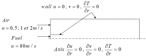
A cylindrical geometry 450 mm in diameter and 1800 mm in length is used as a combustion chamber, a menu of a line for injecting fuel (methane or hydrogen) 10 mm in diameter and 50 mm in length (Figure 1).
Figure 1. Geometrical configuration
The air enters at an ambient temperature of 300° K and with a speed of 0.5 m / s. The fuel (CH4 or H2) has the same temperature (300° K) and at a speed of 80m / s as shown in the following figure. A refinement of the areas in the vicinity of the inlet and the axis of symmetry of the combustion chamber has been taken into account to capture the various phenomena that can occur in these areas, in particular the speed gradients.
In order to compare the results of the two fuels (CH4 and H2) the temperature and some species are calculated in different sections.
Our comparison was carried out on the two fuels for the case of a flow rate corresponding to the air inlet speed of 0.5 m / s and 80m / s for the fuel inlet speed and in well-defined positions such that ((a): x = 300mm, (b): x = 400mm, (c): x = 500mm) for the profiles.
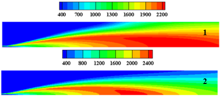
The temperature is raised in the center of the combustion chamber "the hot zone", and decreases until the wall temperature (300° k).
Figure 2. Temperature Contours of the two fuels: 1. (CH4) et 2. (H2)
(Tmax(CH4) =2320°k et Tmax(H2)=2490°k)
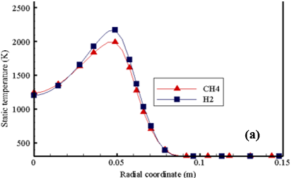
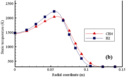
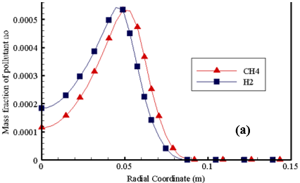
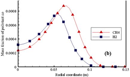
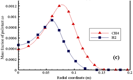
Note that the temperature is higher for the H2 fuel in these stations than for the CH4 fuel (Figure 2). This is for stations that are greater than x = 300cm (Figure 3: (a), (b) and (c)). The NO molar fractions for CH4 fuel at these stations are higher than for those for H2 fuel.
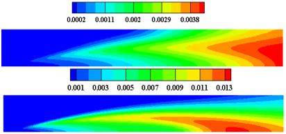
It is always observed that the fractions are high in the center of the combustion chamber (Figure 4, 5), it is the reaction zone.
Figure 3. Temperature profiles of CH4 and H2
Figure 4. No Mass fraction contours of CH4 and H2
Figure 5. The molar fraction of pollutant NO for two fuels (CH4 et H2) at different position ((a): x = 300 mm, (b): x = 400 mm, (c): x = 500 mm, (d): x = 600mm, (e): x = 900 mm, (f): x = 1200 mm, (g): x =1500 mm)
The hydrogen fuel in the reaction mixture minus the nitrogen monoxide NO in the combustion products Figure 6.
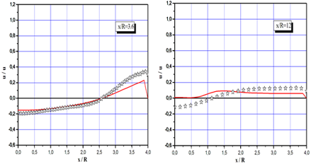
In another study for swirling non premixed flame, we validate the obtained results by the experimental [16]. This validation is conducted by the axial velocity profiles, Figure 7.
In the first, we can be seen the existence of negative values, that explain the creation of the recirculation zone near the injection and the at the axis. It is the right prediction of the corner zone (CRZ) and the toroidal zone (CTRZ) [21].
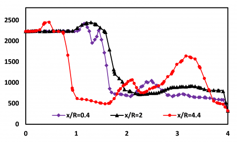
The goal of this study is to predict the effect of the recirculation zone at the formation of the NOx in the swirling flame. Figure 8 shows the temperature evolution profiles, it can be seen that the profiles take two peak, the first peak in before the recirculation toroidal recirculation zone and the last after the recirculation zone.
Figure 6. Validation with experiment of axial velocity at different section
Figure 7. Profile of temperature in deferent section
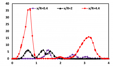
Figure 8. Profile of NO ppm: Prompt NOx Formation
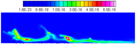
Figure 9. Contours of NO Mass Fraction: Thermal NOx Formation
The NOx formation in the swirling flame it is also described in the Figure 9. The NOx profiles are plotted in deferent section, it can be concluded that the formation of NOx is linked to the evolution of temperature. Where there are high values the formation is greater, Figure 10. Formation of NOx is linked to the evolution of temperate. where there are high values the formation is greater, it is also important to give the description of the properties of this flame, where we have plotted the evolution curves of Ch4, O2 and CO2, these results confirm our prediction Figure 11. The last point in this study is a CFD prediction of all flame proprieties presented by the O2, CO2, H2O and OH contours Figures 12, 13 and 14.
Figure 10. CH4, O2 and CO2 evolution at different section
Figure 11. Contour of the O2 consomation evolution in the combustion process
Figure 12. Contour of H2O evolution formation in the combustion process
Figure 13. Contour of CO2 in the combustion chamber
Figure 14. Contour of OH in the combustion process
In this work we studied numerically a flow with the reaction of chemical species in an enclosure similar to a combustion chamber. The flow being ax symmetric and turbulent, as can be encountered in diffusion flames (non-premixed), using the k-ε model and the Eddy Dissipation model. We used the Fluent CFD code. Our numerical simulations were presented for two different fuels (CH4, H2) in order to see their effects on the maximum temperature and the production of NOx.
There are several different factors which directly influence the formation of NOx but the most important is the high temperature. Another important factor is the nature of the fuel due to the fact that the formation of NOx is dependent on the fuel used for combustion.
Oxides and oxides of nitrogen are the main pollutants emitted by combustion plants. NOx has effects on the destruction of the ozone layer as well as on the ecosystem and human health. Pollutant releases can be controlled by regulations that encourage manufacturers to use combustion, to improve engines technologically or by reducing energy consumption by manufacturers.
Hydrogen is a clean fuel and can be obtained by renewable means (e.g. biomass or cracking of water by solar energy [14]). The replacement of a fuel by hydrogen is beneficial, because it is clean but remains dangerous and requires a lot of modifications in the installations, given its diffusion and its very high calorific value, Pci H2 = 119,930 kJ / kg, PciCH4 = 50020 kJ / kg [14]. To benefit in the short term from hydrogen, the solution is to replace part (10% by volume for example) of the fuel in a lean combustion, this makes it possible to keep the same installations with minimal modifications. This study it concluded by CFD prediction a swirling non premixed flame, where the description of the NOx formation is very clear and low than the other precedent flames.
The authors thank the General Directorate of Scientific Research and Technological Development (DGRSDT) of Algeria for funding this research, which expressed its preliminary findings with this scientific article.
|
K |
Turbulent Kinetic energy |
|
Mf |
Methane mass flow of kg/h |
|
P |
Pressure, Pas |
|
V |
Radial velocity, m/s |
|
U |
Axial velocity, m/s |
|
W |
Tangential velocity, m/s |
|
Yf |
Methane and hydrogen mass fraction |
|
Re |
Reynolds number |
|
Greek symbols |
|
|
ʋ |
Kinematic viscosity |
|
ε |
Dissipation rate |
|
λ |
Air equivalence ratio |
[1] Antonia, R., Bilger, R. (1973). An experimental investigation of an axisymmetric jet in a co−flowing air stream. Journal of Fluid Mechanics, 61: 805-822. https://doi.org/10.1017/S0022112073000959
[2] Barlow, R.S., Dibble, R.W., Chen, J.Y., Lucht, R.P., (1990). Effect of Damkholer Number on superequilibrium OH concentration in turbulent nonpremixed jet flames. Combustion and Flame, 82(3-4): 235-251. https://doi.org/10.1016/0010-2180(90)90001-8
[3] Tabet, F., Sarhb, B., Gokalp, I. (2009). Hydrogen–hydrocarbon turbulent non-premixed flame structure. International Journal of Hydrogenenergy, 34(11): 5040-5047.
[4] Milleret, J.A., Bowman, C.T. (1989). Mechanism and modeling of nitrogenchemistry in combustion. Dans: Progress in Energy and Combustion Science, 15(4): 287-338. https://doi.org/10.1016/0360-1285(89)90017-8
[5] Dos Santos, R.G., Lecanu, M., Ducruix, S., Gicquel, O., Iacona, E., Veynante, D. (2008). Coupled large eddy simulations of turbulent combustion and radiative heat transfer. Combustion and Flame, 152(3): 387-400. https://doi.org/10.1016/j.combustflame.2007.10.004
[6] Pitsch, H. (2006). Large-eddy simulation of turbulent combustion. Annual Review Fluid Mech., 38: 453-482.
[7] Kurenkov, A., Oberlack, M. (2005). Modelling turbulent premixed combustion using the level set approach for Reynolds averaged models. Flow, Turbulence and Combustion, 74: 387-407. https://doi.org/10.1007/s10494-005-9000-8
[8] Lalmi, D., Hadef, R. (2017). Numerical study of the swirl direction effect at the turbulent diffusion flame characteristics. International Journal of Heat and Technology, 35(3): 520-528. https://doi.org/10.18280/ijht.350308
[9] Lalmi, D., Hadef, R. (2017). Influence of direction of rotation of the swirl at the turbulente diffusion flame proprieties. IEEE International Conference on Green Energy & Conversion Systems At: Hammamet, Tunisia, Tunisia Volume: IEEE Xplore, Hammamet, Tunisia. https://doi.org/10.1109/GECS.2017.8066176
[10] Lalmi, D., Hadef, R. (2015). Numerical simulation of co and counter swirls on the isothermal flow and mixture field in a combustion chamber. Advances and Applications in Fluid Mechanics, AAFM, 18(2): 199-212. http://dx.doi.org/10.17654/AAFMOct2015_199_212
[11] Syred, N., Beer, J.M. (1974). Combustion in swirling flows: A review. Combustion and Flame, 23(2): 143-201. http://dx.doi.org/10.1016/0010-2180(74)90057-1
[12] Pierce, C.D., Moin, P. (1998). Large eddy simulation of a confined coaxial jet with swirl and heat release. AIAA paper, 2892. http://dx.doi.org/10.2514/6.1998-2892
[13] Pierce, C.D., Moin, P. (1998). Method for generating equilibrium swirling in flow conditions. AIAA J, 36(7): 1325-1327. http://dx.doi.org/10.2514/3.13970
[14] Merkle, K., Haessler, H., Büchner, H., Zarzalis, N. (2003). Effect of co-and counter-swirl on the isothermal flow-and mixture-field of an airblast atomizer nozzle. International Journal of Heat and Fluid Flow, 24(4): 529-537. http://dx.doi.org/10.1016/S0142-727X(03)00047-X
[15] Kumar, R., Sood, S., Sheikholeslami, M., Shehzad, S.A. (2017). Nonlinear thermal radiation and cubic autocatalysis chemical reaction effects on the flow of stretched nanofluid under rotational oscillations. Journal of Colloid and Interface Science, 505: 253-265. http://dx.doi.org/10.1016/j.jcis.2017.05.083
[16] Kumar, R., Sood, S. (2017). Combined influence of fluctuations in the temperature and stretching velocity of the sheet on MHD flow of Cu-water nanofluid through rotating porous medium with cubic auto-catalysis chemical reaction. Journal of Molecular Liquids, 237: 347-360. http://dx.doi.org/10.1016/j.molliq.2017.04.054
[17] Zhiyin, Y. (2015). Large-eddy simulation: Past, present and the future. Chinese Journal of Aeronautics, 28(1): 11-24. http://dx.doi.org/10.1016/j.cja.2014.12.007
[18] Lalmi, D., Benseddik, A., Bensaha, H., Bouzaher, M.T., Arrif, T., Guermoui, M., Rabehi, A. (2019). Evaluation and estimation of the inside greenhouse temperature, numerical study with thermal and optical aspect, International Journal of Ambient Energy. https://doi.org/10.1080/01430750.2019.1594369
[19] Triveni, M.K., Panua, R. (2017). Numerical analysis of natural convection in a triangular cavity with different configurations of hot wall. International Journal of Heat and Technology, 35(1): 11-18. https://doi.org/10.18280/ijht.350102
[20] Mansouri, Z., Aouissi, M., Boushaki, T. (2016). A numerical study of swirl effects on the flow and flame dynamics in a lean premixed combustor. International Journal of Heat and Technology, 34(2): 227-235. https://doi.org/10.18280/ijht.340211
[21] Ambethkar, V., Kushawaha, D. (2017). Numerical simulations of fluid flow and heat transfer in a four-sided lid-driven rectangular domain. International Journal of Heat and Technology, 35(2): 273-278. https://doi.org/10.18280/ijht.350207