Ashish Kumar Srivastava* | Akash Dubey | Manish Kumar | Shashi Prakash Dwivedi | Rabesh Kumar Singh | Sanjay Kumar
© 2020 IIETA. This article is published by IIETA and is licensed under the CC BY 4.0 license (http://creativecommons.org/licenses/by/4.0/).
OPEN ACCESS
In the continuously changing scenario of manufacturing industries, the demand for rapid production and specific material component is increased day by day. In this context, the additive manufacturing technique proves a suitable option to develop complex geometry shapes with optimized use of the material as well as energy. In this work, an attempt is to develop a 3D physical component of connecting rod by direct metal laser sintering (DMLS) process. The process parameters such as scanning speed 6m/s, laser power 200 W, layer thickness of 25 µm were kept constant. The same geometry component is also produced by a traditional stir casting method to compare the dimensional accuracy and deviations. The CAD model of the connecting rod was prepared by CATIA V6. All the dimensions were measured by a counter measuring machine (CMM). The surface roughness of both the final product was also measured to discuss the surface quality and physical surface defects. In addition to it, a cost analysis of both the process to develop the same component is also discussed. From the result, it is found that the dimensional error for 3D metal printing component is quite low and occurred in the range of 4 % to 7% in XY, YZ radial and circular plane direction compared to stir casting component 4% to 10% in the same planes. The surface roughness value Ra and Rz for the 3D metal printing surface (2.339 and 8.439 µm ) were quite low compared to stir cast surface (4.417 and 13.372 µm). However, the overall cost of 3D metal printing is higher than the stir casting component.
3D metal printing, Direct Metal Laser Sintering (DMLS), stir casting, dimensional accuracy, surface roughness
3D Metal printing is one of the well-known types of the additive manufacturing process that can be able to develop functional physical products [1, 2]. The main aim is to produce an accurate and precise dimensional product that can be able to meet the desired expectation [3]. The major advantage of the additive manufacturing technique is to develop the component without any wastage of material because of the ability to recycle the material during the operation [4, 5]. The process is also capable of the drop in emissions due to the lesser requirement of raw material [6]. The 3D metal printing process is one of the prominent types of additive manufacturing and is well recognized to produce metallic parts, as an alternative to the other conventional and unconventional processes of production like stir casting, die casting and plastic molding [7]. It is capable of producing complex and intricate shapes with low wastage of material [8]. The various types of 3D metal printing have been explored by the researchers such as binder jetting, powder bed fusion (PBF), sheet metal, vat polymerization, direct deposition etc. PBF has proved an innovative technique to develop the component more accurately. Garmendia et al. [9] worked on surface modification of powder feed stocks by PBF. AlSi10Mg powder was coated by (1 wt.%) copper. Products were printed in build volume platform of 78 × 78 × 55 mm & chamber was flooded with argon to ensuring an oxygen level below 1,000 ppm. The known methods of PBF metal printing are selective laser sintering (SLS) [10], selective laser melting (SLM) [11-13] and direct metal laser sintering [14, 15]. Among these methods (DMLS) is famous due to its freedom for design [16]. It is capable for the fabrication of near net-shaped parts directly from CAD data by melting together different layers with the help of a laser source [17]. The DMLS process is competent in functioning with almost several materials and alloys [18]. The thermal, mechanical, and physical properties of the developed component are found nearly close to the properties obtained by conventional methods. It can construct geometries that are intricate or that are impractical to cast [19]. DMLS can manufacture inimitable parts without special tools as required in casting. DMLS is useful for multiple applications as it is widely used in aerospace industries for things as an air duct, mounting, etc. [20]. It has a large application in the automotive industry and also in the medical industry as per requirements [21]. The previous research on DMLS process explored its vital application in the various fields such as Ti-6Al-4V sheet was developed by Fotovvati et al. [22]. They have discussed the tensile strength of the sheet concerning the effect of process parameters layer thickness, free edge distance and orientation. The turbine engine component made of Inconel 718 has been made by Raj et al. [14] by using DMLS process. They have discussed the corrosion behaviour of the developed component after and before heat treatment.
Stir casting is a liquid state casting method and it is one of the conventional processes of manufacturing to fabricate metallic parts [23]. To develop the metal products like composites, a matrix material is melted in the crucible above its melting temperature and the alloying elements of reinforcements are mixed to it through stirring action [24, 25]. It involves a lot of energy as well as resources to develop products. However, structural efficiency and mechanical properties are found excellent compared to another similar process [26, 27]. Today's manufacturing world demanded lightweight material that has excellent mechanical and thermal properties to increase engine efficiency and structural efficiency [28]. It is also suitable for the process of production of metal matrix composition due to its cost-effectiveness, applicability to mass production, simplicity [29]. In this context, lightweight materials such as aluminum, magnesium, titanium, super alloys, etc. prove a better option for manufacturing industries [30]. However, the challenges are associated with these materials like reduced performance and mechanical properties.
Based on the archival of literature, it has been concluded that both the manufacturing methods DMLS and stir casting are capable to produce the lightweight composites of these engineering materials [31-33]. Most of the research has been focused on the mechanical, tribological and corrosion properties of the components. However, the dimensional stability is equally important to meet the challenges related to mating parts of the automobile and aircraft industries. The dimensional accuracy component produced by stir casting and DMLS process is associated with the defect like shrinkage. The effect of shrinkage may deviate the accuracy in the flatness, cylindricity, perpendicularity etc.
The target of the present work is to compare the dimension accuracy, surface roughness and deviations associated with the component produced by DMLS and traditional stir casting method. The CAD model of the connecting rod was prepared by CATIA V6. All the dimensions such as in XY plane, YZ plane, radial, and circular dimension, roundness, cylindricity, and flatness were measured by counter measuring machine (CMM). The surface roughness of both the final product was also measured to discuss the surface quality and physical surface defects. In addition to it, a cost analysis of both the process to develop the same component is also discussed.
In this work, AA6101 alloy (Al 98.9%, Si 0.50%, and Mg 0.60%) is used a matrix material and collagen powder extracted from chrome contained leather waste along with Al2O3 particles of 10 µm size. Connecting rod of the engine assembly was considered as a case of study to discuss the dimensional deviations, percentage error and surface roughness of the final product developed by 3D metal printing and stir casting route. CATIA V6 was used for generating the 3D CAD model of the connecting rod. Figure 1 shows the 3D CAD model of connecting rod, its dimensions and 2D and 3D view.
Further to make same product from stir casting process, a mould of connection rod is also developed. Proper allowances were taken into consideration while creating the mould design. The 3D CAD model of mould designed for stir casting is shown in Figure 2.
Figure 1. 3D CAD model of connecting rod made on CATIA V6
Figure 2. 3D CAD model of mould designed for connection rod
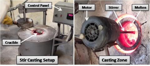
Two metal matrix composite Al6101/Al2O3/Collagen powder was developed by 3D printing (DMLS) and stir casting process. Al6101 alloy in powder form, 5% Al2O3 and 1.25% of collagen powder mixed homogeneously and are directly used in the DMLS machine (Make EOS model M290) to develop 3D component. Figure 3 shows the schematic representation of DMLS process. The specification of machine are as follows: scan speed 6 m/s, laser power 200 W and layer thickness 25 µm with maximum capacity of binding 250 × 250 × 325 mm3. During the process the recoater blade deposits the mixed powder layer one by one, simultaneously sintered by laser beam focused on the selected region, follows the command received from CAD model. The laser melts the layer in a sequential mode and the process run till the completion of geometry. The unused powder material is collected by the collector system attached to the machine. However, in stir casting, Al6101 alloy is melted in the muffle furnace above to its melting temperature. After that the mixture of 5% Al2O3 and 1.25% collagen powder was mixed to it by means of mechanical stirring. When the stirring was completed, the molten for pored to the pre developed die of the connection rod. Figure 4 shows the stir casting setup and casting zone.
The dimensional measurements were carried out by coordinate measuring machine (CMM). The dimensions of both the connecting rod was measured along the printing direction (XY plane), transverse direction (YZ plane) diametral and radial direction. The measurement of flatness, roundness and cylindricity were also conducted by CMM. Surface roughness parameters Ra and Rz were measured by optical profilometer on the top surface of the developed connecting rods. In addition to it cost analysis was also done on the basis of factors like material cost, supporting material cost, machine cost and labour cost.
Figure 3. Schematic representation of direct metal laser sintering
Figure 4. Experimental setup of stir casting and casting zone
The overall cost (OC) of the process is deponds on these factors. In this work the costing was done for per Kg of material consumption by the following equation.
OC (INR) = B1 × B2+ B3 × B4+ (Tpre + Tpost) B5 +Tpre × B6 (1)
B1 is the cost of raw material per Kg, B3 is the cost of supporting material per Kg, B2 and B4 is the actual amount of consumption of raw material and supporting material, respectively. Tpre and Tpost is the pre and post time of processing, respectively in hours. B5 is the cost of labour in working hours and B6 is the cost of machine in calculated per hours.
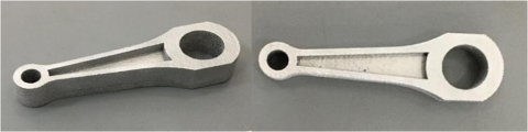
DMLS and stir casting process was used to produce the connecting rod and the same type of material (Al6101/5% Al2O3/1.25% collagen powder) was used for both the processes. Figure 5 shows the images of the component made by 3D printing (DMLS) and stir casting process.
After the development of both the product, the samples were processed for any type of physical surface defects and soft cleaned by the 2000 mesh grit paper. All the dimensions were checked by counter measuring machine (CMM). The dimensions of the connecting rod is named according to their plane and direction. The dimensions in XY plane is named as L1, L2, L3....etc. Similarly T1, T2 in transverse direction (YZ plane), D1, D2, D3 etc of circular dimensions and R1, R2 are in the radial direction. Table 1 shows the dimensional anaysis of connecting rod for both the developed components. The table also replsents the intial dimension of CAD model to compare the dimensional error of connecting rods with respect to CAD dimensions. It is measured that the dimensional error for 3D metal printing component in XY plane is 4.62%, in YZ plane 5.8%, in radial direction 2.44% and in circular direction 1.86% compared to stir casting component in XY plane 7.86%, in YZ plane 10%, in radial direction 4.45% and in circular direction 4.76%.
Table 2 shows the measurements of flatness, cylindricity and roundness. The flatness (0.1720 for 3D metal printing, 0.2719 for stir casted) cylindricity (0.0002for 3D metal printing, 0.0005 for stir casted) and roundness (0.0687for 3D metal printing, 0.0989 for stir casted) of the 3D metal printed component is better that the stir casted component.
Figure 5. Sample of Al6101/5% Al2O3/1.25% collagen powder (a) 3D printed component (b) Stir casted
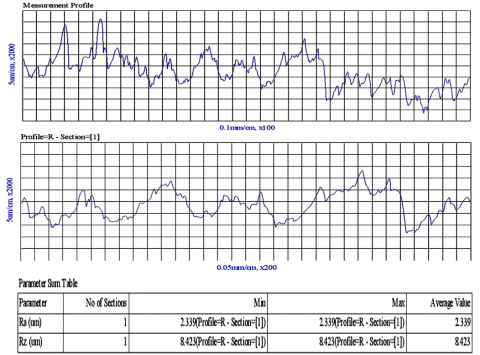
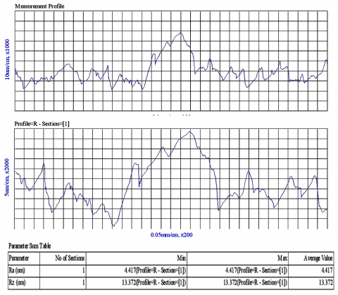
The surface roughness of top surface of both the component was also measured by optical profilometer. Figure 6 and Figure 7 shows the surface roughness report generated by profilometer for both 3D metal printed and stir casted component, respectively. Surface roughness curve reveals the lower and upper peaks of the 3D printed and stir casted component. It is observed from the profile curve that the stir casted component follows the larger deviation between the upper peaks and lower valleys compared to smaller gap obtained for the 3D printed component. The values of roughness is closer, in case of 3D printed component due to less flaws on the printed surface compared to stir casted one. The measured value of parameters of surface roughness Ra and Rz is given in Table 3. It is observed from the measurment values that the roughness parameter of 3D metal printed is quite improved that the stir casted component. It is attributed to the fact that the posibilities of formation of porosity, blow holes and surface defects are larger in stir casting route due to trapping of air bubbles during the process. However, in the 3D metal printing, the layer by layer deposition of metal is done by laser sintering which is comparitively less affected by the trapping of air.
Table 1. Dimensional measurement of both the connecting rod made by 3D printing and stir casting
|
XY plane linear dimension |
|||||
|
Dimension |
CAD Dimension |
Metal Printing |
Stir Casting |
% error metal printing |
% error stir casting |
|
L1 |
72.5 |
70.69 |
70 |
2.49 |
3.44 |
|
L2 |
55 |
53.84 |
53.5 |
2.10 |
2.7 |
|
L3 |
37.5 |
37.17 |
36 |
.88 |
4 |
|
L4 |
5 |
5.11 |
4.8 |
2.2 |
4 |
|
L5 |
7.76 |
7.62 |
7 |
1.67 |
9.7 |
|
Average % error |
1.86 |
4.76 |
|||
|
Maximum % error |
2.49 |
9.7 |
|||
|
STDEV |
0.62 |
2.80 |
|||
|
YZ plane linear dimension |
|||||
|
T1 |
10 |
10.58 |
11 |
5.8 |
10 |
|
Circular dimension of connecting rod |
|||||
|
D1 |
14 |
14.24 |
14.9 |
1.7 |
6.4 |
|
D2 |
24 |
24.5 |
25 |
2 |
4.16 |
|
D3 |
6 |
6.82 |
7 |
13.6 |
16.6 |
|
D4 |
11 |
10.87 |
11.5 |
1.18 |
4.5 |
|
Average % error |
4.62 |
7.86 |
|||
|
Maximum % error |
13.6 |
16.6 |
|||
|
STDEV |
5.98 |
5.87 |
|||
|
Radial dimension of connecting rod |
|||||
|
R1 |
35 |
35.03 |
35.5 |
0.08 |
1.4 |
|
R2 |
8 |
8.39 |
8.6 |
4.8 |
7.5 |
|
Average % error |
2.44 |
4.45 |
|||
|
Maximum % error |
4.8 |
7.5 |
|||
|
STDEV |
3.34 |
4.31 |
|||
Table 2. Measurment of flatness, cylindricity and roundness
|
S.N |
Measurement |
DMLS |
Stir casted |
|
1 |
Flatness (mm) |
0.1720 |
0.2719 |
|
2 |
Cylindricity (mm) |
0.0002 |
0.0005 |
|
3 |
Roundness (mm) |
0.0687 |
0.0989 |
Table 3. Measured surface roughness parameter
|
S.N. |
Roughness Prameters (um) |
3D Printed |
Stir casting |
|
1 |
Ra |
2.339 |
4.417 |
|
2 |
Rz |
8.439 |
13.372 |
Figure 6. Surface roughness report for 3D metal printed component
Figure 7. Surface roughness report for stir casted component
Figure 8 shows the comparative analysis of average percentage error. It seems from the graph that metal printing is better than the stir casting in terms of the dimensional accuracy of components. The larger dimensional deviation is found in transverse plane (YZ plane) in stir casting route. It may be associated with the defects related to the mould design or subjected to the defects like misruns etc.
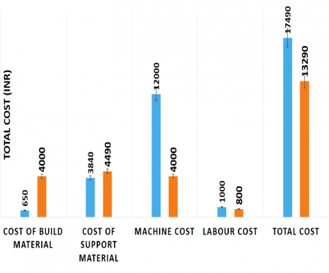
Figure 9 shows the summary of cost analysis report of this study. It is observed from the graph that the overall printing cost of 3D component is quite high compared to stir casting component. However, the individual cost of build material and support material in case of stir casting is high compared to metal printing. The major costing of 3D printing is associated with the machining cost which is nearly 1/3rd of the overall cost of the product. Since the metal printers are sophisticated and advance machines, therefore skilled labour is required. it leads to the higher labour cost of 3D printing compared to stir casting.
Figure 8. Comparison of average percentage error in dimension of 3D Metal printing and stir casting
Figure 9. Cost comparison chart
In this paper comparative dimensional study and surface roughness of the connecting rod produced by two different manufacturing technologies namely 3D Metal printing (DMLS) and stir casting have been evaluated. Comparison is carried out on the basis of dimensional accuracy, form errors (roundness, cylindricity and flatness) and surface roughness. At last the comparative cost is also discussed. The results revealed the advantage of using 3D printing method over the tradition method stir casting because of the low percentage error of dimensions. The dimensional error for 3D metal printing component in XY plane is 4.62%, in YZ plane 5.8%, in radial direction 2.44% and in circular direction 1.86% compared to stir casting component in XY plane 7.86%, in YZ plane 10%, in radial direction 4.45% and in circular direction 4.76%. The average percentage error in DA of metal printing is less than stir casting. The other dimensions like roundness, cylindricity and flatness and surface roughness Ra and Rz (2.339 and 8.439 µm) of the 3D metal printed component is also found better than the stir cast component. However, the overall printing cost of 3D component is quite high compared to stir casting component. The major costing of 3D printing is associated with the machining cost which is nearly 1/3rd of the overall cost of the product. In view of future prospects, the comparative analysis of characterization related to mechanical, tribological and corrosion properties are still needed to investigate in detail to take suitable decision on the selection of manufacturing method.
This work is supported and funded by CRIP funding under TEQIP-III and Dr. A.P.J. Abdul Kalam Technical University, Lucknow.
[1] Beyca, O.F., Hancerliogullari, G., Yazici, I. (2018). Additive manufacturing technologies and applications. In: Industry 4.0: Managing the Digital Transformation. Springer Series in Advanced Manufacturing. Springer, Cham, pp. 217-234. https://doi.org/10.1007/978-3-319-57870-5_13
[2] Srivastava, A.K., Kumar, N., Dixit, A.R. (2021). Friction stir additive manufacturing - An innovative tool to enhance mechanical and microstructural properties. Materials Science and Engineering: B, 263: 114832, https://doi.org/10.1016/j.mseb.2020.114832
[3] Singh, S., Ramakrishna, S., Singh, R. (2017). Material issues in additive manufacturing: A review. Journal of Manufacturing Processes, 25: 185-200. https://doi.org/10.1016/j.jmapro.2016.11.006
[4] Bandyopadhyay, A., Heer, B. (2018). Additive manufacturing of multi-material structures. Materials Science and Engineering, R: Reports, 129: 1-16. https://doi.org/10.1016/j.mser.2018.04.001
[5] Ligon, S.C., Liska, R., Stampfl, J., Gurr, M., Mülhaupt, R. (2017). Polymers for 3D printing and customized additive manufacturing. Chemical Reviews, 117(15): 10212-10290. https://doi.org/10.1021/acs.chemrev.7b00074
[6] Kumar Maurya, N., Rastogi, V., Singh, P. (2019). Investigation of dimensional accuracy and international tolerance grades of 3D printed polycarbonate parts. Materials Today: Proceedings, 25(Part 4): 537-543. https://doi.org/10.1016/j.matpr.2019.06.007
[7] Yang, L., Hsu, K., Baughman, B., Godfrey, D., Medina, F., Menon, Ma., Wiener, S. (2017). Introduction to additive manufacturing. In: Additive Manufacturing of Metals: The Technology, Materials, Design and Production. Springer Series in Advanced Manufacturing. Springer, Cham. https://doi.org/10.1007/978-3-319-55128-9_1
[8] Ivanova, O., Williams, C., Campbell, T. (2013). Additive manufacturing (AM) and nanotechnology: Promises and challenges. Rapid Prototyping Journal, 19(5): 353-364. https://doi.org/10.1108/RPJ-12-2011-0127
[9] Garmendia, X., Chalker, S., Bilton, M., Sutcliffe, C.J., Chalker, P.R. (2020). Microstructure and mechanical properties of Cu-modified AlSi10Mg fabricated by Laser-Powder Bed Fusion, Materialia, 9: 100590. https://doi.org/10.1016/j.mtla.2020.100590
[10] Zhang, Z., Yao, X.X., Ge, P. (2020). Phase-field-model-based analysis of the effects of powder particle on porosities and densities in selective laser sintering additive manufacturing. International Journal of Mechanical Sciences, 166: 105230. https://doi.org/10.1016/j.ijmecsci.2019.105230
[11] Qian, G.A., Jian, Z.M., Pan, X.N., Berto, F. (2020). In-situ investigation on fatigue behaviors of Ti-6Al-4V manufactured by selective laser melting. International Journal of Fatigue, 133: 105424. https://doi.org/10.1016/j.ijfatigue.2019.105424
[12] Sutton, A.T., Kriewall, C.S., Leu, M.C., Newkirk, J.W., Brown, B. (2020). Characterization of laser spatter and condensate generated during the selective laser melting of 304L stainless steel powder. Additive Manufacturing, 31: 100904. https://doi.org/10.1016/j.addma.2019.100904
[13] Wei, K., Yang, Q.D., Ling, B., Yang, X.J., Xie, H.Q., Qu, Z.L., Fang, D.N. (2020). Mechanical properties of Invar 36 alloy additively manufactured by selective laser melting. Materials Science and Engineering: A, 772: 138799. https://doi.org/10.1016/j.msea.2019.138799
[14] Anush Raj, B., Winowlin Jappes, J.T., Adam Khan, M., Dillibabu, V., Brintha, N.C. (2020). Direct Metal Laser Sintered (DMLS) process to develop Inconel 718 alloy forturbine engine components. Optik, 202: 163735. https://doi.org/10.1016/j.ijleo.2019.163735
[15] Avanzini, A., Battni, D., Gelfi, M., Petrogalli, C., Pola, A., Tocci, M. (2019). Investigation of fatigue strength of sand - blasted DMLS AlSi10Mg alloy. Procedia Structural Integrity, 18: 119-128. https://doi.org/10.1016/j.prostr.2019.08.146
[16] Maurya, N.K., Rastogi, V., Singh, P. (2019). Experimental and computational investigation on mechanical properties of reinforced additive manufactured component. EVERGREEN Joint Journal of Novel Carbon Resource Sciences & Green Asia Strategy, 6(3): 207-214. https://doi.org/10.5109/2349296
[17] Bonnard, R., Mognol, P., Hascoët, J.Y. (2010). A new digital chain for additive manufacturing processes. Virtual and Physical Prototyping, 5(2): 75-88. https://doi.org/10.1080/17452751003696916
[18] Ahuja, B., Karg, M., Schmidt, M. (2015). Additive manufacturing in production: Challenges and opportunities. Proc. SPIE 9353, Laser 3D Manufacturing II, 935304, San Francisco, California, United States. https://doi.org/10.1117/12.2082521
[19] Labonnote, N., Rønnquist, A., Manum, B., Rüther, P. (2016). Additive construction: State-of-the-art, challenges and opportunities. Automation in Construction, 72(Part 3): 347-366. https://doi.org/10.1016/j.autcon.2016.08.026
[20] Lavoie, M., Addis, J.L. (2018). Harnessing the potential of additive manufacturing technologies: Challenges and opportunities for entrepreneurial strategies. International Journal of Innovation Studies, 2(4): 123-136. https://doi.org/10.1016/j.ijis.2018.11.001
[21] Li, L., Post, B., Kunc, V., Elliott, A.M., Parans Paranthaman, M. (2017). Additive manufacturing of near-net-shape bonded magnets: Prospects and challenges. Scripta Materialia, 135: 100-104. https://doi.org/10.1016/j.scriptamat.2016.12.035
[22] Fotovvati, B., Alireza Etesami, S., Asadi, E. (2019). Process-property-geometry correlations for additively-manufactured Ti-6Al-4V sheet. Materials Science & Engineering A, 760: 431-447. https://doi.org/10.1016/j.msea.2019.06.020
[23] Das, S., Chandrasekaran, M., Samanta, S., Kayaroganam, P. (2019). Fabrication and tribological study of AA6061 hybrid metal matrix composites reinforced with SiC/B4C nanoparticles. Industrial Lubrication and Tribology, 71(1): 83-93. https://doi.org/10.1108/ILT-05-2018-0166
[24] Dwivedi, S.P., Srivastava, A.K. (2020). Utilization of chrome containing leather waste in development of aluminium based green composite material. International Journal of Precision Engineering and Manufacturing-Green Technology, 7: 781-790. https://doi.org/10.1007/s40684-019-00179-1
[25] Nag, A., Srivastava, A.K., Dixit, A.R., Mandal, A., Das, A.K. (2018). Surface integrity analysis of wire-EDM on in-situ hybrid composite A359/Al2O3/B4C. Materials TODAY PROCEEdings, 5(11): 24632-2464. https://doi.org/10.1016/j.matpr.2018.10.261
[26] Srivastava, A.K., Sharma, B., Saju, B.R., Shukla, A., Saxena, A., Maurya, N.K. (2020). Effect of Graphene nanoparticles on microstructural and mechanical properties of aluminum based nanocomposites fabricated by stir casting. World Journal of Engineering, 17(6): 859-866. https://doi.org/10.1108/WJE-04-2020-0128
[27] Mardi, K.B., Dixit, A.R., Srivastava, A.K., Mallick, A., Scucka, J., Hlavacek, P., Hloch, S., Zelenak, M. (2018). Effect of Water Pressure During Abrasive Waterjet Machining of Mg-Based Nanocomposite. In: Singh M., Kushvah B., Seth G., Prakash J. (eds) Applications of Fluid Dynamics. Lecture Notes in Mechanical Engineering. Springer, Singapore. https://doi.org/10.1007/978-981-10-5329-0_46
[28] Srivastava, A.K., Nag, A., Dixit, A.R., Tiwari, S., Srivastava, V.S. (2019). Parametric study during abrasive water jet turning of hybrid metal matrix composite. In: Hloch S., Klichová D., Krolczyk G., Chattopadhyaya S., Ruppenthalová L. (eds) Advances in Manufacturing Engineering and Materials. Lecture Notes in Mechanical Engineering. Springer, Cham. https://doi.org/10.1007/978-3-319-99353-9_9
[29] Srivastava, A., Nag, A., Dixit, A., Hloch, S., Tiwari, S., Scucka, J., Pachauri, P. (2019). Surface integrity in wire-EDM tangential turning of in situ hybrid metal matrix composite A359/B4C/Al2O3. Science and Engineering of Composite Materials, 26(1): 122-133. https://doi.org/10.1515/secm-2017-0391
[30] Srivastava, A.K., Gupta, Y., Patel, S., Tiwari, S.K., Pandey, S. (2019). Metal matrix composites-a review on synthesis and characterization. IOP Conf. Series: Materials Science and Engineering, 691: 012077. https://doi.org/10.1088/1757-899X/691/1/012077
[31] Maurya, N.K., Rastogi, V., Singh, P. (2020). An overview of mechanical properties and form error for rapid prototyping. CIRP Journal of Manufacturing Science and Technology, 29(Part A): 53-70. https://doi.org/10.1016/j.cirpj.2020.02.003
[32] Nag, A., Srivastava, A.K., Dixit, A.R., Chattopadhyaya, S., Mandal, A., Klichová, D., Hlavacek, P., Zelenak, M., Hloch, S. (2018). Influence of abrasive water jet turning parameters on variation of diameter of hybrid metal matrix composite. In: Singh M., Kushvah B., Seth G., Prakash J. (eds) Applications of Fluid Dynamics. Lecture Notes in Mechanical Engineering. Springer, Singapore. https://doi.org/10.1007/978-981-10-5329-0_36
[33] Srivastava, A.K., Dwivedi, S.P., Maurya, N.K., Maurya, M. (2020). 3D visualization and topographical analysis in turning of hybrid MMC by CNC Lathe SPRINT 16TC made of BATLIBOI. EVERGREEN Joint Journal of Novel Carbon Resource Sciences & Green Asia Strategy, 7(2): 202-208. https://doi.org/10.5109/4055217