Kaijun Cai* | Weiming Zhang | Jiang Li | Hongfei Zhao
OPEN ACCESS
The lack of virtual prototype impedes the accurate measurement of the maintenance time for mechanical products. Inspired by cumulative time estimation, this paper designs a framework for maintenance time prediction, and details its implementation steps. Then, several maintenance tasks were simulated in an environment constructed on the digital manufacturing software DELMIA. The simulation environment includes virtual prototype, virtual human and maintenance tools. Among them, the posture of the virtual human in the maintenance process was obtained by the VBScript language, which covers four types of motions (i.e. body motion, upper limb motion, grab & place motion and operation motion). Based on the posture data, the time consumption of each type of motion was predicted by the modular arrangement of predetermined time standard (MOD), and then corrected in light of the visibility and reachability of maintenance motions. Finally, the proposed measurement method was applied to the maintenance, disassembly and assembly of an actual engine. The results show that the measured results agree well with the actual results, indicating that our method is feasible and effective.
mechanical products, maintenance time measurement, virtual prototype, modular arrangement of predetermined time standard (MOD), maintenance motion
Maintenance activities are important for maintaining the good operating condition of mechanical products, and the maintenance time reflects the degree of difficulty of the maintenance. In the design and R&D of products, the maintenance time should be measured as early as possible, so as to provide a reference for the optimization of structural design and reduce deign re-work times, thereby cutting down the full-life cycle costs [1].
Maintenance time includes average maintenance time, average preventive maintenance time, etc. [2]. The national standard Maintainability Allocation and Prediction Handbook provides a variety of maintenance time measurement methods, wherein the cumulative time estimation is a more elaborate method [3]. It calculates the time of each maintenance event, operation, and activity according to the maintenance experience data, the design scheme and the maintenance plan. However, in the early stage of design and R&D, the maintenance experience and data are insufficient due to the lack of physical prototype. In response, many scholars have proposed solutions based on the idea of cumulative time estimation. On the one hand, literatures [4, 5] introduced time measurement methods such as the Modular Arrangement of Predetermined Time Standard (MODAPTS, MOD for short) in the industrial engineering predetermined time standard system. MOD method is an elaborate and simple method which considers that the time required for people to complete a same basic motion is the same. The time value of a one-time finger motion, 0.129s, is taken as the basic unit MOD, that is, 1MOD=0.129s, and the motion time of other parts is the integral multiple of it [6]. By analyzing the basic motions included in the maintenance process, we can directly measure the maintenance time. However, the MOD method is derived from the research on the motions of workers in the manufacturing system, compare to it, the motions in the maintenance process of the mechanical products have lower repeatability, the working environment is more complicated, and the direct application of MOD method has larger errors. On the other hand, with the development of virtual reality technology, the application of virtual prototype-related technologies and methods has gradually become a research hotspot [7] in the design and R&D of products. The literatures [8-10] developed virtual maintenance training systems, but couldn’t obtain maintenance time indicators. Literatures [11-15] studied the maintenance time prediction methods based on virtual maintenance, but lacked reasonable classification of maintenance motions, and the accuracy of time measurement was affected.
Aiming at above problems, this paper proposes a mechanical product maintenance time measurement method with higher precision, which has important reference value for the maintenance indicator verification and structural layout design in the product design and R&D stage.
Mechanical product maintenance includes 7 maintenance activities such as fault location, fault isolation, disassembly, replacement, assembly, adjustment and inspection [3], in which disassembly and assembly are the main maintenance activities, and their completion times have a significant impact on the total maintenance time, therefore, the measurement of disassembly and assembly time is the main object of this paper.
The flow of the product maintenance time measurement is shown in Figure 1. According to the maintenance plan, the product maintenance process is decomposed into several basic maintenance motions (simple motions with shorter durations, such as screwing nuts, moving parts, etc.). In DELMIA, the maintenance process is simulated and the motion information of the virtual human is obtained based on the virtual prototypes, then according to basic maintenance motion time measurement method, the time of each maintenance motion is obtained and accumulated to get the maintenance disassembly and assembly time, moreover, combined with the list of replaceable units and the failure rates, we can get the average maintenance time, and other indicators.
Figure 1. Flow of maintenance time measurement method
With DELMIA as the simulation platform, a virtual maintenance environment including product virtual prototypes, virtual human, and maintenance tools is built in this paper.
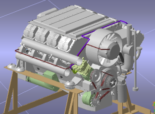
A virtual prototype of a mechanical product is shown in Figure 2(a). In the prototype, the size of the sub-assembly and parts and their mating relationships are totally identical to the physical prototype, and are classified according to the structure of assembly-two major mechanisms and four major systems-subassembly-parts.
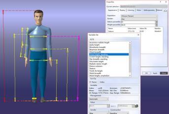
A virtual human was built with DELMIA's Human Builder module. According to the size data of various parts of the human body in the national standard Chinese Adult Body Size [16], the virtual human was edited, as shown in Figure 2(b). Maintenance tools such as wrenches and sleeves were built as well, as shown in Figure 2(c).
(a) A product virtual prototype
(b) A virtual human Model
(c) Maintenance tool model
Figure 2. Virtual maintenance environment construction
In the engine maintenance process, people’s basic maintenance motions are divided into four types: body movement, upper limb movement, operation movement, and grab/place movement. The DELMIA ergonomics module was used to simulate the maintenance process, through the second-development interface and VBScript language programming, the motion information of the virtual human could be obtained. Combined with the motion information and the MOD method, this paper proposes a time measurement method for the above four-type motions in the virtue environment.
4.1 Time measurement of body movement motions
The motion unit of body movement is mainly the walking motion. When using virtual human to simulate the body movement motions, we can use the following code to obtain the position information of the start-and-stop postures of the virtual human:
Set sWKBody=sWKManikin.Body//Get the body of the virtual human
sWKBody.GetGlobalPosition(sWKPosition)//Get arrayOfVariantOfDouble, this array is used to represent global coordinates of the virtual human. There are 12 Double-type data, of which the first 9 represent a 3×3 rotation matrix, and the last 3 constitute the displacement vector.
The moving length L can be obtained from the information of the start-and-stop postures. The MOD method stipulates that the time value of a walking motion is 5 MOD and the moving distance is 0.6 m, so the number of motion units is n=L/0.6, n rounds up to an integer, and the body moving time TBM=5n MOD.
4.2 Time measurement of upper limb movement motions and grab/place movement motions
Upper limb movement motions and grab/place movement motions would constitute a coherent movement. The time of upper limb movement motions is mainly affected by upper limb moving distance and the weight of the holding object. For the upper limb moving distance, first obtain the position information of the hand’s start-and-stop postures, taking the left hand as an example:
Set WorkerBody=sWKManikin.Body//Get the body of the virtual human
Set LHandNode=WorkerBody.GetItem("LsHaCPr")//Get the left hand node of the virtual human
Set LHand=LHandNode.GetSegment(0)//Left hand segment
P=LHand.EndPosition//Hand end coordinates:
Table 1. Upper limb motion time
|
Moving distance x/cm |
Motion time TUL |
|
x<5 |
1MOD |
|
5≤x≤15 |
2MOD |
|
15≤x≤30 |
3MOD |
|
30≤x≤45 |
4MOD |
|
x≥45 |
5MOD |
According to the hand position information, calculate the moving distance x . Refer to the standards of the upper limb moving distance and motion time in the MOD method (as shown in Table 1) [6], it can be converted into motion time TUL .
Investigating the effects of heavy objects can be achieved by the following code:
Set AttachedObjNum=LHand.AttachSize//If AttachedObjNum=0, the virtual human is in a bare hand state, otherwise it holds a heavy object.
Set nAttachedObj=LHand.GetAttachedObject (n)//Get the heavy object node and its mass Mn, wherein n=0 To AttachedObjNum-1.
According to the weight of the heavy object and the weight factor principle of the MOD method, correct the motion time [6], as shown in the following equation:
${{T}_{W}}=\left[ {\left( {{M}_{n}}-2 \right)}/{4}\; \right]+1$ (1)
where TW is the additional time, its unit is MOD, it rounds down to an integer.
The time of grab/place movement motions is mainly affected by maintenance personnel adjustment, judgment, and other factors. Referring to the time value method of the MOD method [6], and based on the characteristics of the engine maintenance process, the time of grab/place movement motions TGP is shown as Table 2. Therefore, the time of upper limb movement motions and grab/place movement motions is: TUGP=TUL+TW+TGP.
Table 2. Time of grab/place movement motions
|
Motion type |
Time TGP |
Characteristics |
|
|
Grab motion G |
Touch motion G0 |
0MOD |
Simply touch the object and there is no requirement for the grab motion. |
|
Simple Grab G1 |
1MOD |
There are requirements for the hand shape of the grab motion, there is no obstacle nearby, such as tightening/loosening the screws or nuts with bare hand. |
|
|
Complex Grab G3 |
3MOD |
There are obstacles, the target is vulnerable and has requirement for the grabbing position; attention should be paid, such as operating complex tools, etc. |
|
|
Place motion P |
Unconscious place P0 |
0MOD |
Simple place, there is no special requirement for the placing motion, and no special attention is required. |
|
Approximate location fit P2 |
2MOD |
Need to pay attention to determine the approximate location of the object, such as putting the tools into the toolbox regularly. |
|
|
Place motion P5 |
5MOD |
Need to pay attention to accurately place the targets in the specified position, such as vulnerable parts, aiming screwdriver to a screw, etc. |
|
4.3 Time measurement of operation movement motions
The engine maintenance process involves the operation of a large number of fasteners and parts with mating relationships. Operation movement motions have the characteristics of complex motion trajectory and many evolved joints of upper limbs. Simply applying DELMIA simulation animation or MOD method can hardly measure the time of the motions accurately. Operation movement motions can be divided into two types: bare hand and tool operation. The operating objects can be divided into bolts, studs, screws, all 12 kinds of fasteners and other parts. For different objects and operating status, this paper proposes two kinds of time measurement methods for operation movement motions.
Method 1. When the maintenance personnel twist the fasteners by hand, he/she mainly uses the finger or wrist motions, for the operation time for each twist TOMT, we can directly refer to the measurement standard of MOD method, take 1 MOD and 2 MOD, respectively.
Method 2. When using tools to disassemble parts or use bare-hands to disassemble other parts other than fasteners, we can’t direct use the moving distance of the hand of the virtual human to measure the motion time. For example, when using a wrench to tighten a bolt, the hand position is almost motionless, while the wrist, the forearm and the upper arm would move. According to the idea in the MOD method that the moving distance of the finger is equal to the corresponding moving time [6], this paper proposes to measure the degree of freedom and the rotation angle of each segment of the upper limb of the virtual human and calculate the equivalent moving distance, thereby judging the motion level and obtaining the method of motion time, the specific process is as follows:
Step 1. Determine the object is within the scope of Method 2. Use the following code to get the degree of freedom (DoF) of the right upper arm segment:
Set sWKSegmenti = sWKBody.GetItem ("LSArAr")//Get the right upper arm of the virtual human
Set sWKDOFi = sWKSegmenti.GetItem ("DOF1")//Get the bending/stretching DoF of the right upper arm
The DoF of each segment of the upper limb includes: upper arm bending/stretching θAFL, extending/flexing θAAB, inward spinning/outward spinning θAMR; forearm bending/stretching θFFL, inward spinning/outward spinning θFPR; hand bending/stretching θHFL, radium-ward bending/ulna-ward bending θHRD.
Step 2. According to the MOD method, the upper limb movements are divided into: hand level, forearm level, upper arm level, and upper arm straight level, and the corresponding time values are 2MOD, 3MOD, 4MOD, 5MOD, respectively. Since we use tools to disassemble the parts or use bare hands to disassemble parts other than fasteners, so there’s no finger level motions. The DoF values of each segment and the moving distance S of the fingertip are used to judge the level of the motion.
Step 3. Accumulate the time of each motion unit to get the motion time of the operation movement TO=∑TOMTn.
The motion level determination is a key step to implement the method. Taking the upper arm straight level as an example, its specific determination process is as follows:
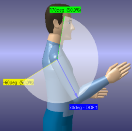
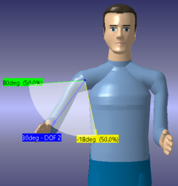
Step 1. The 3 DoF of the upper arm are shown as Figure 3, the shaded area represents the moving range of the DoF of the upper arm. According to 50-percent adult male data in the GB-10000, set the length of each upper arm segment of the virtual human as: upper arm LAR=313mm, forearm LFR =237mm, hand LH=183mm [16].
(a) Bending / Stretching
(b) Extending / Flexing
(c) Inward spinning/Outward spinning
Figure 3. DoF of upper arm segment
According to the code in Section 3.2, measure the start-and-stop positions of the hand end and calculate to get the moving distance S.
Step 2. The bending/stretching θAFL and extending/flexing θAAB of the upper arm are the motion decomposition of the upper arm around the shoulder joint in the respective planes, by calculation we can get the expression of their relationship with the upper arm rotation angle θAR as follows:
$\begin{align}&{{\theta }_{AR}}=2\arcsin \left\{ 0.5\left[ 1-\sin {{\theta }_{AFL2}} \right. \right.\sin {{\theta }_{AFL1}}- \\&\cos \left( {{\theta }_{AAB2}}-{{\theta }_{AAB1}} \right)\cos {{\theta }_{AFL2}}\cos {{\theta }_{AFL1}}{{\left. \right]}^{1/2}}\left. \right\} \\\end{align}$ (2)
Step 3. When the upper arm, forearm and hand are in the straight state, the total length of the upper limb is =733mm. When the hand end moves 450mm, the rotation angle of the upper arm is θAR=35.2°.
The inward/outward spinning of the upper arm is the rotation motion of the forearm and the hand around the axis of the upper arm, the total length is L=420mm, when the hand end moves 450mm, the rotation angle of the upper arm is θAMR=61.4°.
Step 4. Determine the level of the motion. Among θAR, θAMR, and S, as long as one meets the condition, it can be determined that the motion is upper arm straight level, that is, the judging criterion for upper arm straight level motion is:
(θAR≥35.2°)∨(θAMR≥61.4°)∨(S≥450mm)
Motion time TOMT=5MOD=0.645s.
Similarly, the judging criterion for the upper arm level motion is:
[(θAR<35.2°)∧(θAMR<61.4°)∧(S<450mm)]∧[(θAR≥23.4°)∨(θAMR≥40.9°)∨(S≥300mm)]
Motion time TOMT=4MOD=0.516s.
The judging criterion for the forearm level motion is:
[(θAR<23.4°)∧(θFR<40.9°)∧(S<300mm)]∧[(θAR≥11.7°)∨(θFR≥20.5°)∨(S≥150mm)]
where in θFR is the forearm’s rotation angle, which is determined by the upper arm’s inward/outward spinning θAMR and the forearm’s bending/stretching θFFL, the relationship is:
$\begin{align}&{{\theta }_{AR}}=2\arcsin \left\{ 0.5\left[ 1-\sin {{\theta }_{FFL2}} \right. \right.\sin {{\theta }_{FFL1}}-\\&\cos\left( {{\theta }_{AMR2}}-{{\theta }_{AMR1}} \right)\cos {{\theta }_{FFL2}}\cos {{\theta }_{FFL1}}{{\left. \right]}^{1/2}}\left. \right\} \\\end{align}$ (3)
Motion time TOMT=3MOD=0.387s.
The judging criterion for the hand level motion is:
[(θAR<11.7°)∧(θH<47.0°)∧(S<150mm)]∧[(θAR≥3.9°)∨(θH≥15.7°)∨(S≥50mm)]
Wherein θH is the hand’s rotation angle, which is determined by the hand’s bending/stretching θHFL and radium-ward/ulna-ward bending θHRD, the relationship is:
$\begin{align}& {{\theta }_{H}}=2\arcsin \left\{ 0.5\left[ 1-\sin {{\theta }_{HRD2}} \right. \right.\sin {{\theta }_{HRD1}}- \\ & \cos \left( {{\theta }_{HFL2}}-{{\theta }_{HFL1}} \right)\cos {{\theta }_{HRD2}}\cos {{\theta }_{HRD1}}{{\left. \right]}^{1/2}}\left. \right\} \\\end{align}$ (4)
In summary, according to the type and number of basic maintenance motions included in the disassembly and assembly activities during the maintenance event, we can get the disassembly and assembly time of the maintenance event as:
The above time measurement method assumes that the motions are completed under the ideal conditions of good visibility, good reachability and comfortable working postures. Due to the influence of the size, structure and layout of the maintenance object, the actual maintenance process is often in a non-ideal state. Therefore, in order to further reduce the measurement error, this paper studies the influences of visibility, reachability and working postures on the motion time and the correction method.
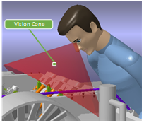
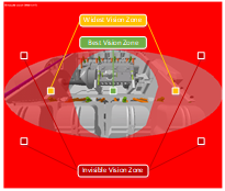
5.1 The influence of visibility
In the simulation process, by using Manikin Tools, the virtual human tools in DELMIA, the vision cone of a person under a certain posture could be generated, and various vision zones are generated automatically, as shown in Figure 4. According to the standard of the best vision in ergonomics [17], the entire vision zone is divided into the best vision zone, the widest vision zone and the invisible vision zone, and angle values of each zone are set in the DELMIA. The criterion of the visibility level and the corresponding time correction coefficient RVi are given, as shown in Table 3.
(a) Vision cone
(b) Vision zones
Figure 4. Virtual human vision cone and vision zones
Table 3. Visibility level and time correction coefficient
|
Visibility level i |
Description |
Time correction coefficient RVi |
|
1 |
The object is located in the best vision zone and there is no obstacle, the observation could be conducted clearly and the operation process is completely visible. |
0 |
|
2 |
The object is located in the widest vision zone or partially sheltered, the operation process is partially visible, and the operation is affected. |
0.5 |
|
3 |
The object is located in the invisible vision zone or is completely sheltered, the operation process is not visible, and can only be operated through sensory or maintenance experience. |
1.0 |
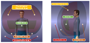
5.2 The influence of reachability
Through the DELMIA contact bounding box tool, the reachable area of the upper limb of a person under a certain posture can be generated, as shown in Figure 5. It was divided into ideal area, extended area, maximal reachable area and unreachable area.
The reachability level and the corresponding time correction coefficient RRi are shown in Table 4.
(a) Front (b) Profile
Figure 5. Virtual human upper limb reachable range
Table 4. Visibility level and time correction coefficient
|
Visibility level i |
Description |
Time correction coefficient RRi |
|
1 |
The operating object is in the ideal reachable range; there is no interference in the movement of the upper limbs. |
0 |
|
2 |
The operating object is located in the maximal reachable range, use upper limb straightening and other motions; there is no interference in the upper limb movement. |
0.5 |
|
3 |
The operating object is in the maximal reachable area, the operator needs to take whole-body straightening and similar motions that cannot be hold for long; there is interference in the movement process of the upper limbs, but it is still reachable. |
1.0 |
5.3 The influence of working postures
The Rapid Upper Limb Assessment (RULA) can be performed on postures using the posture analysis tools in DELMIA, as shown in Figure 6.
Figure 6. RULA assessment in DELMIA
The above figure shows the RULA’s scores of the various parts of the body under a certain posture, then according to the scoring system, it gives a total score. Based on the results of the RULA assessment, the time correction coefficient RP = RULA/6 [5].
Based on the evaluation of the influencing factors of the above motion time, the corrected motion time can be obtained as follows:
${T}'=T\times \left( 1+{{R}_{V}}+{{R}_{R}}+{{R}_{P}} \right)$ (6)
where T is the ideal motion time calculated according to the method in Section 4.
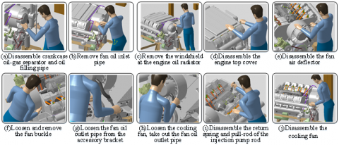
A certain type of engine has the characteristics of many components and complex structure. As a main component of the engine cooling system, the cooling fan is very important for the maintenance of engine and directly influences the reliability and economy of the engine. The disassembly process mainly includes the disassembly of crankcase oil-gas separator and oil filling pipe, the disassembly of fan oil inlet pipe, the disassembly of windshield, the disassembly of engine top cover, etc., all 10 steps. The entire disassembly process of the cooling fan maintenance is simulated in DELMIA, and Figure 7 shows the simulation of each disassembly step.
The 10 main disassembly steps of the cooling fan were decomposed into the basic maintenance motions, and each motion time was measured, with Step 9 of the disassembly of the return spring and the pull-rod of the injection pump rod as an example, the motions and time of some basic maintenance are shown in Table 5.
Table 5. Some basic maintenance motions and time measurement included in disassembly step 9
|
No. |
Basic maintenance motion |
Estimated time (s) |
No. |
Basic maintenance motion |
Estimated time (s) |
|
1 |
Posture adjustment 1 |
1.200 |
8 |
Grab the screw and gasket |
0.387 |
|
2 |
Move upper limbs 1 |
0.516 |
9 |
Move upper limbs 4 |
0.516 |
|
3 |
Use the tool to screw 90°×6 |
10.062 |
10 |
Place |
0.258 |
|
4 |
Move upper limbs 2 |
0.516 |
11 |
Move upper limbs 5 |
0.645 |
|
5 |
Posture adjustment 2, place the tool |
2.187 |
12 |
Grab the pull-rod return spring |
0.258 |
|
6 |
Posture adjustment 3, move upper limbs 3 |
2.420 |
... |
...... |
...... |
|
7 |
Screw by hand 180°×6 |
6.192 |
Total time |
121.812 |
|
Select a number of personnel with certain maintenance experience, and let each person complete the maintenance task several times. As shown in Figure 8, the operation time was measured by the stopwatch, and the average completion time was taken as the actual time.
The actual time obtained, the measurement time of the proposed method, the estimated time of the MOD method, and the simulation animation time of the entire disassembly process of the DELMIA simulation are listed in Table 6. The comparison is shown in Figure 9, wherein the abscissa is the disassembly steps, and the ordinate is the completion time of each step, in seconds.
According to the data in the table and the comparison chart we can see that, the time measured by the proposed method (green dotted line) is closer to the actual time (red solid line), while the times obtained by the MOD method (yellow dotted line) and the DELMIA simulation animation time (blue dotted line) are less compared to the actual time, it’s mainly because the MOD method is derived from the motion time of skilled workers in the production line, and the same motion takes less time than the maintenance process. While in the DELMIA simulated maintenance process, the operator needs to manually edit the motions of the virtual human. Due to the influence of subjective judgment and the complexity of the motion editing, the simulation animation can hardly cover all the motion details. Compared with these two common methods, the measurement method proposed in this paper is more accurate.
In addition, for steps 2 and 7 of the cooling fan disassembly process, the error rates of the proposed method, the MOD method, and simulation animation are relatively small; and for steps 3, 5, and 8, the error rates of the above three methods are relatively large. After analysis, the main reason is that the personnel are in the more ideal working state in steps 2 and 7, the influence of each time influencing factors is smaller and the operation movement motions of the personnel are less, so the calculation results of the three methods are not much different. While in steps 3, 5, and 8, the visibility, reachability, and working postures of the personnel are not ideal enough, so that the value of the time correction coefficient is larger, and the calculation results of the three methods differ greatly. This phenomenon also proves the effectiveness of the proposed method.
Figure 7. Simulation of the cooling fan disassembly process
Figure 8. Measure actual disassembly time using stopwatch
Table 6. Comparison of disassembly time of each method
|
Steps |
DELMIA Simulation animation (s) |
MOD method (s) |
The proposed method (s) |
Actual time (s) |
|
Disassemble crankcase oil-gas separator and oil filling pipe |
43.135 |
49.378 |
69.859 |
72.075 |
|
Remove fan oil inlet pipe |
20.933 |
29.519 |
40.971 |
36.119 |
|
Remove the windshield at the engine oil radiator |
27.324 |
31.915 |
51.054 |
55.249 |
|
Disassemble the engine top cover |
93.075 |
130.693 |
170.354 |
191.861 |
|
Disassemble the fan air deflector |
30.891 |
47.473 |
66.503 |
70.738 |
|
Loosen and remove the fan buckle |
28.212 |
32.775 |
40.817 |
44.094 |
|
Loosen the fan oil outlet pipe from the accessory bracket |
30.976 |
33.029 |
39.398 |
36.652 |
|
Loosen the cooling fan from the front baffle and take out the fan oil outlet pipe |
37.106 |
45.659 |
58.458 |
64.307 |
|
Disassemble the injection pump return spring and pull-rod |
78.462 |
98.859 |
121.812 |
141.032 |
|
Disassemble the cooling fan |
18.721 |
20.665 |
30.895 |
31.586 |
|
Total time |
408.835 |
519.965 |
690.121 |
743.713 |
Figure 9. Comparison of disassembly time of each method
This paper proposed a method for measuring the maintenance time of mechanical products based on virtual prototype.
(1) According to the idea of the cumulative time estimation method in the national standard, this paper constructed a framework for maintenance time prediction methods, and described the flow of the maintenance time prediction.
(2) In the simulation platform DELMIA, this study established a virtual maintenance environment including virtual prototypes, virtual human, and maintenance tools.
(3) Using DELMIA, this paper simulated the product maintenance process, and used the VBScript language to obtain virtual human movement information. It proposed to divide the basic maintenance motions that make up the maintenance process into four types: body movement, upper limb movement, grab/place movement and operation movement. And then, combined with the MOD method and virtual maintenance simulation, aiming at the characteristics of the motions of each kind, this paper proposed the corresponding time measurement method so as to improve the accuracy. From the example we can see that, compared with the MOD method and the DELMIA simulation animation method, the measurement accuracy of the proposed method is more ideal.
(4) Applying the proposed method to the maintenance time measurement in the initial stage of mechanical product design and R&D is of great reference value for reducing design re-work times, number of prototypes, design and research cycle, and the life cycle cost, as well as verifying maintenance indicators and optimizing structural layout design.
[1] Zhang L, Yu YL. (2002). GRASP based maintenance time and man-hour model. China Mechanical Engineering 13(7): 577-579. https://doi.org/10.3321/j.issn:1004-132X.2002.07.012
[2] Zhang LY, Liu Y, Liu J. (2016). Maintenance time prediction using virtual reality. Journal of Computer-Aided Design & Computer Graphics 28(8): 1383-1392. https://doi.org/10.3969/j.issn.1003-9775.2016.08.021
[3] Xu XS, Zhu XD, Gan MZ. (1994). Maintainability allocation and prediction handbook. China Commission of Science Technology and Industry for National Defense.
[4] Zhou D, Zhou XX, Guo ZY. (2016). A maintenance time prediction method considering ergonomics through virtual reality simulation. Springer Plus 5(1): 1239-1260. https://doi.org/10.1186/s40064-016-2886-x
[5] Gironimo GD, Martino CD, Lanzotti A. (2012). Improving MTM-UAS to predetermine automotive maintenance times. International Journal on Interactive Design & Manufacturing 6(4): 265-273. https://doi.org/10.1007/s12008-012-0158-8
[6] Yi S, Guo F. (2014), Fundament of industrial engineering (2nd edition). China Machine Press, Beijing.
[7] Zhou D, Chen J, Lv C, Cao Q. (2016). A method for integrating ergonomics analysis into maintainability design in a virtual environment. International Journal of Industrial Ergonomics 54: 154-163. https://doi.org/10.1016/j.ergon.2016.06.003
[8] Yu H, Peng G, Liu W. (2013). A practical method for measuring product maintainability in a virtual environment. Assembly Automation 31(1): 53-61. https://doi.org/10.1108/01445151111104173
[9] Qiu S, Yang YF, Fan X, He Q. (2014). Human factors automatic evaluation for entire maintenance processes in virtual environment. Assembly Automation 34(4): 357-369. https://doi.org/10.1108/AA-04-2014-028
[10] Lockett HL, Arvanitopoulos-Darginis K. (2017). An automated maintainability prediction tool integrated with computer aided design. Procedia CIRP 60: 440-445. https://doi.org/10.1016/j.procir.2017.01.007
[11] Sun Y, Huang JY, Wang W. (2010). Quantitative evaluation method of product disassembly based on parts failure rate and disassembly time. Chinese Journal of Mechanical Engineering 46(13): 147-154. https://doi.org/10.3901/JEM.2010.13.147
[12] Geng J, Lv C, Zhou D, Li Y, Wang ZL. (2014). Compensation-based methodology for maintenance time prediction in a virtual environment. Simulation Modelling Practice & Theory 47: 92-109. https://doi.org/10.1016/j.simpat.2014.05.008
[13] Reményi C, Staudacher S. (2014). Systematic simulation based approach for the identification and implementation of a scheduling rule in the aircraft engine maintenance. International Journal of Production Economics 147(5): 94-107. https://doi.org/10.1016/j.ijpe.2012.10.022
[14] Rao Y, Xu B, Jing T, Zhang F, Zhao XY. (2017). The current status and future perspectives of virtual maintenance. Procedia Computer Science 107(C): 58-63. https://doi.org/10.1016/j.procs.2017.03.056
[15] Geng J, Li Y, Wang RR, Wang ZL, Lv C, Zhou D. (2017). A virtual maintenance-based approach for satellite assembling and troubleshooting assessment. Acta Astronautica 138: 434-453. https://doi.org/10.1016/j.actaastro.2017.06.018
[16] GB/T 10000 (1988). Human dimensions of Chinese adults, China Standard Press, Beijing.
[17] Marzano A, Friel I, Erkoyuncu JA, Court S. (2015). Design of a virtual reality framework for maintainability and assimilability test of complex systems. Procedia CIRP 37: 242-247. https://doi.org/10.1016/j.procir.2015.08.067