Hassen Reghioui | Saad Belhamdi | Ammar Abdelkarim | Hellali Lallouani
OPEN ACCESS
The aim of this article is to improve the performance of the classical direct torque control (DTC) of doubly star induction motor (DSIM) drive by reducing the ripples level in electromagnetic torque and stator flux. For this reason, we present different strategies to enhance the performance of DTC such as DTC_SVPWM. This technique replaces hysteresis controllers by two (PI) controllers to generate the direct and the quadrature voltage components in d-q frame. However it is difficult to adjust the parameters of PI controller due to the complexity of the control system. The self-tuning PI fuzzy controller was proposed to adjust the PI parameters in this paper. Simulation is carried out using MATLAB/SIMULINK and the performance of the proposed fuzzy system is analyses. The simulation results show that the proposed method can significantly reduce the torque ripple and is suitable for various motor at different working state.
doubly star induction motor (DSIM), DTC, SVPWM, PI controller, Type-1 fuzzy, logic control
The double star induction machine (DSIM) belongs to the multiphase machines category. It has been proposed for different fields of industry that need high power such as electric hybrid vehicles, locomotive traction and ship propulsion and other applications which requires safeness conditions such as aerospace and offshore wind energy systems [1]. Other potential advantages of the multi-phase drives when compared to the standard three-phase are:
(1) the possibility to divide the controlled power on more inverter legs.
(2) the current stress of the semiconductor devices decreases proportionally with the phase number.
(3) reducing the torque pulsations at high frequency, rotor harmonic currents, and current per phase without increasing the voltage per phase [2]. Therefore, it is very beneficial to apply a control strategy which maintains these advantages in case of open-phase fault.
The aim of our work is based on the utilization of a simple model of the DSIM, this machine has several advantages such as [3-4] reliability, robustness and meets the best criteria of behavior that the simple induction machine, because it reduces electromagnetic torque ripples and improves the power factor.
Direct control of the torque and flux of the induction motor, known as DTC (Direct Torque control) [5], was introduced by Takahashi et al. [6, 7]. This control technique provides a solution to the problems posed by vector control. It has the advantage of being independent of the rotor parameters of the machine, it provides a faster torque response and has a simpler configuration that does not require mechanical sensors or coordinate transformations. It has drawbacks that are related to the presence of significant ripple flux and torque, in addition to the switching frequency of the inverter which is variable [8]. In order to reduce flow and torque ripple and to improve DTC performance, some techniques are considered that can provide solutions to problems and improve DTC performance. The most common solution to this problem is to use spatial vector modulation [9], depending on the torque and the reference flow. In DTC-SVPWM, PI controllers replace hysterical comparators [10]. SVM-based DTC can generate voltage vectors with adjustable amplitude and phase [11]. These techniques are taken into account to obtain an optimized adjustment of integral proportional controllers (PI) in DTC-SVM control loops, such as rotor speed, electromagnetic torque, stator flux coupling and stator flux estimation [12], so that it can more precisely control the electromagnetic torque and the stator flux. As a result, two main advantages can be achieved, namely the reduction of torque and flux ripples and the fixed switching frequency [13]. In this case, the model of the system must be known. In addition, because of the use of PI controllers, parameter variations will influence the dynamic performance and stability of the system, resulting in a waste of robustness. In addition, the machine parameters being obtained by conventional identification experiments, measurement errors can not be avoided. In addition, the value of the parameters can not be fixed because the physical properties are influenced by the condition of the environment [14].
This study presents an SVM-DTC strategy based on fuzzy logic to improve the performance of a dual-star induction motor. Flux and torque errors act as an input for fuzzy logic controllers (FLC) that produce an optimal spatial vector output to reduce errors. The main advantage of the FLC is that it does not need an accurate mathematical model of the system, on the other hand ensures high performance in speed response under different operating conditions more than PI controller [15]. By using this control strategy, the advantages of SVM control and fuzzy logic are combined. The response is studied using Matlab / Simulink for the proposed method and the results are analyzed.
In this paper, two different DTC-SVM diagrams will be compared in the direct control method, DTC-SVM with a classic PI control and DTC-SVM with an FLC controller. After the introduction we provide in the second section the mathematical model for DSIM. In the third section, we study the DTC-SVM control technique using PI. We then study the DTC-SVM control technique with FLC control technology in section IV. Section V shows the simulation results to compare the performance of the PI and FLC controller to direct DSIM torque control under different operating conditions (load torque, reference velocity, and parameter changes). The section VI concludes this paper.
To derive the machine model of a double star induction motor (DSIM), the following assumptions have been made: space harmonique, magnetic saturation, and core losses are neglected [16].
The electrical state variables in "α, β" system are the electrical flux, and the input variable in the precedent system. The model of DSIM in α, β reference can be written in the following from [17]:
$\frac{d X}{d t}=A \cdot X+B \cdot U$ (1)
Such as:
$[X]=\left[\begin{array}{llll}\Phi_{S 1 \alpha} & \Phi_{S 2 \alpha} & \Phi_{S 1 \beta} & \Phi_{S 2 \beta}& \Phi_{r \alpha}& \Phi_{r \beta}\end{array}\right]^{T}$,
$[U]=\left[V_{S 1 \alpha} \quad V_{S 2 \alpha}\quad V_{S 1 \beta} \quad V_{S 2 \beta} 00\right]^{T}$,
where:
$V_{S 1, \alpha \beta}, V_{S 2, \alpha \beta}$: Stator voltages αβ components.
$\Phi_{S 1, \alpha \beta}, \Phi_{S 2, \alpha \beta}, \Phi_{r, \alpha \beta}$: Stator and rotor flux αβ components.
The system matrices arc given by:
$A=\left[\begin{array}{cccccc}\frac{L_{a}}{T_{s 1} \cdot L_{s 1}}-\frac{1}{T_{s 1}} & \frac{L_{a}}{T_{s 1} \cdot L_{s 2}} & 0 & 0 & \frac{L_{a}}{T_{s 1} \cdot L_{r}} & 0 \\ \frac{L_{a}}{T_{s 2} \cdot L_{s 1}} & \frac{L_{a}}{T_{s 2} \cdot L_{s 2}}-\frac{1}{T_{s 2}} & 0 & 0 & \frac{L_{a}}{T_{s 2} \cdot L_{r}} & 0 \\ 0 & 0 & \frac{L_{a}}{T_{s 1} \cdot L_{s 1}}-\frac{1}{T_{s 1}} & \frac{L_{a}}{T_{s 1} \cdot L_{s 2}} & 0 & \frac{L_{a}}{T_{s 1} \cdot L_{r}} \\ 0 & 0 & \frac{L_{a}}{T_{s 2} \cdot L_{s 2}} & \frac{L_{a}}{T_{s 2} \cdot L_{s 2}}-\frac{1}{T_{s 2}} & 0 & \frac{L_{a}}{T_{s 2} \cdot L_{r}} \\ \frac{L_{a}}{T_{r} L_{s 1}} & \frac{L_{a}}{T_{r} L_{s 2}} & 0 & 0 & \frac{L_{a}}{T_{r} \cdot L_{r}}-\frac{1}{T_{r}} & \omega_{r} \\ 0 & 0 & \frac{L_{a}}{T_{r} L_{s 1}} & \frac{L_{a}}{T_{r} L_{s 2}} & -\omega_{r} & \frac{L_{a}}{T_{r} L_{r}}-\frac{1}{T_{r}}\end{array}\right]$
and
$B=\left[\begin{array}{llllll}1 & 0 & 0 & 0 & 0 & 0 \\ 0 & 1 & 0 & 0 & 0 & 0 \\ 0 & 0 & 1 & 0 & 0 & 0 \\ 0 & 0 & 0 & 1 & 0 & 0 \\ 0 & 0 & 0 & 0 & 0 & 0 \\ 0 & 0 & 0 & 0 & 0 & 0\end{array}\right]$
In addition, the electromagnetic torque can be ex-pressed by:
$T_{\mathrm{e}}=p \frac{L_{m}}{L_{m}+L_{r}}\left[\Phi_{r \alpha}\left(i_{s 1 \beta}+i_{s 2 \beta}\right)-\Phi_{r \beta}\left(i_{s 1 \alpha}+i_{s 2 \alpha}\right)\right]$ (2)
The mechanical equation of the motor can be expressed as:
$T_{\mathrm{e}}=T_{r}+\frac{\mathrm{K}_{\mathrm{f}}}{\mathrm{p}} \omega_{\mathrm{r}}+\frac{J}{\mathrm{p}} \dot{\omega}_{\mathrm{r}}$ (3)
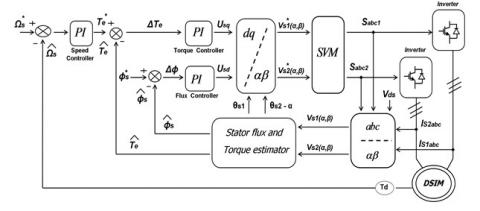
This control structure has the advantages of vector control and direct torque control. In order to overcome the disadvantages of conventional DTC [18], and operates at a constant switching frequency, in this scheme, there are two integral proportional (PI) type controllers instead of the hysteresis band to regulate the torque and amplitude of the flux.
The output of the PI flux and torque controllers can be interpreted as the reference stator voltage components (Uds1,2, Uqs1,2) are the stator flux oriented coordinates (d-q), converted these d-q coordinate components to α-β components [10].
Outputs are, (Uds1,2, Uqs1,2) can be written as:
$U_{d s 1,2}=\left(K_{p \Phi}+\frac{K_{I \Phi}}{s}\right)\left(\Phi_{s}^{*}-\Phi_{s}\right)$ (4)
$U_{q{s1,2}}=\left(K_{p T}+\frac{K_{I T}}{s}\right)\left(T_{e}^{*}-T_{e}\right)$ (5)
$T_{e}=p\left[\Phi_{s 1 \alpha} \cdot i_{s 1 \beta}+\Phi_{s 2 \alpha} \cdot i_{s 2 \beta}\right.$$\left.-\Phi_{s 1 \beta} \cdot i_{s 1 \alpha}+\Phi_{s 2 \beta} \cdot i_{s 2 \alpha}\right]$ (6)
expressions of the two stator voltage vector of the double star induction machine, in the fixed system (α, β) are given by the following equation [10, 19].
$\left[\begin{array}{l}V_{s 1 \alpha} \\ V_{s 1 \beta}\end{array}\right]=\left[\begin{array}{cc}\cos \theta_{s 1} & -\sin \theta_{s 1} \\ \sin \theta_{s 1} & \cos \theta_{s 1}\end{array}\right] \cdot\left[\begin{array}{c}U_{d s 1} \\ U_{q s 1}\end{array}\right]$ (7)
For the second stator, in our case δ=30°:
$\left[\begin{array}{l}V_{s 2 \alpha} \\ V_{s 2 \beta}\end{array}\right]=$$\left[\begin{array}{cc}\cos \left(\theta_{s 2}-\delta\right) & -\sin \left(\theta_{s 2}-\delta\right) \\ \sin \left(\theta_{s 2}-\delta\right) & \cos \left(\theta_{s 2}-\delta\right)\end{array}\right] \cdot\left[\begin{array}{c}U_{d s 2} \\ U_{q s 2}\end{array}\right]$ (8)
Figure 1. Block diagram of DTC-SVM control using regulator PI
4.1 Approach description
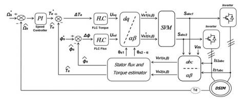
The direct torque fuzzy control scheme (DTFC) proposed in this work employs the space vector modulation. The scheme is given in Figure 2 shows basic fuzzy logic control strategy. The classical PI regulators for flux and torque were replaced by two fuzzy logic controllers. The stator flux and torque references are compared to the values calculated in flux and torque estimator and the corresponding errors are sending to the Direct Torque Fuzzy Controllers of the voltage inverter stage control system [18, 20].
Figure 2. Block diagram of DTC-SVM control using regulator fuzzy logic
4.2 Design of fuzzy PI controller
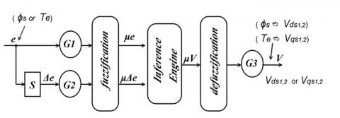
Figure 3. Basic structure of fuzzy logic controller
Design of PI controller is quite complicated since it requires accurate mathematical model of the system and also has slower and poor transient responses such as overshoots during dynamic change in torque, oscillation in speed, high settling time and high torque ripple. Fuzzy logic control is the process of formulating the mapping from a given input to an output using fuzzy logic. It has some advantages such as it does not need any exact mathematical method [21, 22]. As shown in Figure 3.
Generally speaking, a fuzzy logic controller consists of three main parts: fuzzification, fuzzy reasoning and defuzzification [23]. Input variables are the error between commanding value and real value of the flux or the torque and their derivative.
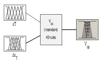
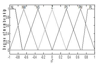
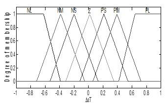
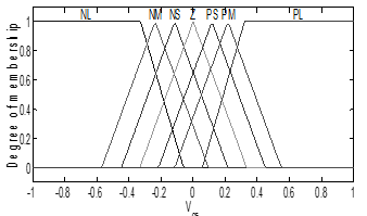
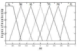
The torque fuzzy logic regulator variables memberships and output surface are representing in Figure 4.
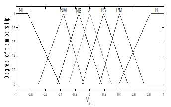
Figure 5 shows the Flux fuzzy logic regulator variables memberships and his output surface.
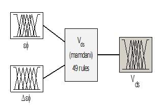
(a) Input-output of fuzzy logic torque controller
(b) Membership functions of torque error
(c) Membership functions of the change of torque error
(d) Membership functions of output voltage in q-reference frame
Figure 4. Fuzzy logic torque controller
(a) Input-output of fuzzy logic flux controller
(b) Membership functions of flux error
(c) Membership functions of the change of flux error
(d) Membership functions of output voltage in d-reference frame
Figure 5. Fuzzy logic flux controller
Fuzzy inference is achieved through language rules. These rules are the most important part of the controller and define the type of control used. Proper rule design leads to the desired performance of the control system [21]. The fuzzy logic control rules are defined in Table 1, which produces outputs from fuzzy logic flux and torque controllers, used as reference stator voltage components, is supplied to the stage. SVM inverter. The control of the input stage is used to obtain the maximum operation of the DC voltage and the unit power factor at the input of the converter [24].
Table 1. The definition of the fuzzy logic control rules
|
e de |
NL |
NM |
NS |
Z |
PS |
PM |
PL |
|
NL |
NL |
NL |
NL |
NL |
NM |
NS |
Z |
|
NM |
NL |
NL |
NL |
NM |
NS |
Z |
PS |
|
NS |
NL |
NL |
NM |
NS |
Z |
PS |
PM |
|
Z |
NL |
NM |
NS |
Z |
PS |
PM |
PL |
|
PS |
NM |
NS |
Z |
PS |
PM |
PL |
PL |
|
PM |
NS |
Z |
PS |
PM |
PL |
PL |
PL |
|
PL |
Z |
PS |
PM |
PL |
PL |
PL |
PL |
Fuzzy has seven membership functions for the inputs and an output are Negative Large (NL), Negative Medium (NM), Negative Small (NS), zero(Z), Positive Small (PS), Positive Medium (PM) and Positive Large (PL). Rules used in fuzzy logic controller for the DTC-SVM scheme are listed in Table 1.
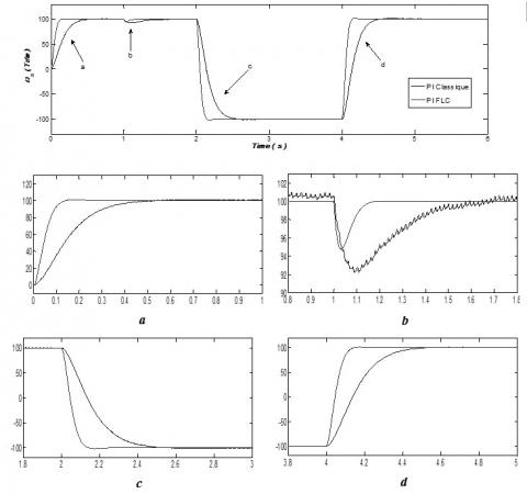
The proposed scheme was implemented with Matlab/Simulink to evaluate its performance. The parameters of the DSIM are summarized in the appendix. The results of the simulation of these two regulators in both transient and permanent regimes and in order to facilitate the comparison of performance between these two regulators. To this end, the control system has been tested under different operating conditions, analyzing the influence of load variation and reversal of direction of rotation, we have chosen the reference flow of 1.2 Wb, a torque application resistant to 14 Nm at t=1 s, a change in direction of rotation form 100 rad/s to -100 rad/s.
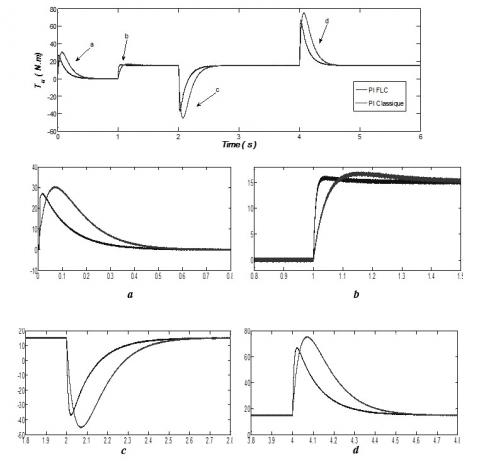
Form the figure 6. Introduces comparisons between DTC-SVM based on FLC controllers on the one hand and DTC-SVM based on PI controllers on the other hand under the same sampling period, as torque dynamics is more fast for DTC-SVM based FLC compared DTC-SVM controllers based on PI controllers.
From the figure 6. it can also be seen the improvement in motors acceleration and the change in motors torque using the Fuzzy PI and it shows less overshoot than classical controller. On the other hand, Fuzzy PI controller has a smoother speed response and more robust from the load torque changes and speed inversion.
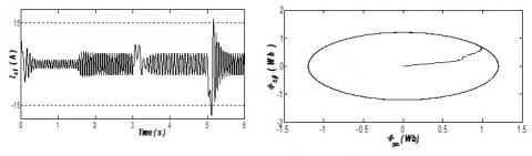
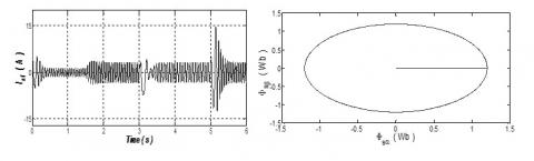
Figures 8 and 9 show, there is a stator current overshoot at the set point change, which leads us to consider an appropriate limitation of a monitoring of peak currents supported by the inverter, and the trajectory of the stator flux is practically circular, so its amplitude remains constant.
Figure 6. The torque evolution of different controllers (fuzzy and PI)
Figure 7. The speed evolution of different controllers (fuzzy and PI)
Figure 8. Stator flow current and stator flow path of this classical PI controller with DTC-SVPWM system
Figure 9. Stator flow current and stator flow path of this fuzzy PI controller with DTC-SVPWM system
In this work, we introduced the integration fuzzy of logical controllers (FLC). The application of the DTC-SVPWM-based on FLC method on dual stator induction machines (DSIM) has been done to improved conventional strategy which uses the linear PI controllers. The proposed control strategy maintains a constant switching frequency using the space vector modulation. In addition, the used fuzzy logic torque and flux controllers instead of PI show clearly that the torque ripples have been reduced significantly; the flux shows better sine waveform and quick response of rotor speed. The FLC is useful for many applications (high-speed, multi-stage induction motors) and achieve good performance and high robustness. As a conclusion, the combination of DTC with SVM and FLC controllers play a strategic role in the development of high-performance DSIM machines.
The parameters of the machine used for simulation are listed below [16]:
|
Rr=2.12(Ω) |
Rotor resistance |
|
Ls1,2=0.022(H) |
Stators 1,2 inductances |
|
Lr= 0.006(H) |
Rotor inductance |
|
Lm=0.3672(H) |
Mutual inductance |
|
Kf=0.001 (Nms/rad) |
Friction coefficient |
|
J=0.00625(Nms2/rad) |
Moment of inertia |
|
P=4.5(kW) |
DSIM mechanical power |
|
220/380(V) |
Stator voltage |
|
50(Hz) |
Stator frequency |
|
p=1 |
Pole pair number |
List of abbreviations and symbols
|
DSIM |
Doubly Star Induction Motor |
|
DTC |
Direct Torque Control |
|
SVM |
Space Vector Modulation |
|
SVPWM |
Space Vector based PWM |
|
PI |
Proportional and Integral |
|
FLC |
Fuzzy Logic Controller |
|
Ωr |
The rotor angular speed |
|
Te |
Electromagnetic torque |
|
Tr |
Load torque |
|
Kf |
Friction coefficient |
|
J |
Moment of inertia |
|
P |
Number of pole pairs |
|
θs |
Angle between stator and rotor flux |
[1] Layadi, N., Zeghlache, S., Berrabah, F., Bentouhami, L. (2017). Comparative study between sliding mode control and bckstepping control for double star induction machine (DSIM) under current sensor faults. International Journal of Information Technology and Electrical Engineering, 6(6): 67-77.
[2] Merabet, E., Abdessemed, R., Bentouhami, L., Bendjedou, Y. (2013). Speed control of a dual stator windings induction machine using fuzzy logic controller. J. Electr. Eng, 13(1): 22-27.
[3] Layadi, N., Zeghlache, S., Djerioui, A., Mekki, H., Berrabah, F. (2019). Adaptive RBFNN strategy for fault tolerant control: application to dsim under broken rotor bars fault. IJ Intelligent Systems and Applications, 2: 49-61. http://dx.doi.org/10.5815/ijisa.2019.02.06
[4] Lallouani, H., Belhamdi, S. (2018). Direct torque control of doubly star induction motor using fuzzy logic speed controller. IAES International Journal of Artificial Intelligence (IJ-AI), 7(1): 42-53. http://doi.org/10.11591/ijai.v7.i1.pp42-53
[5] Sudheer, H., Sf, K., Sarvesh, B. (2017). Improved sensorless direct torque control of induction motor using fuzzy logic and neural network based duty ratio controller. IAES International Journal of Artificial Intelligence, 6(2): 79-90.
[6] Takahashi, I., Noguchi, T. (1986). A new quick-response and high-efficiency control strategy of an induction motor. IEEE Transactions on Industry applications, (5): 820-827. http://dx.doi.org/10.1109/TIA.1986.4504799
[7] Depenbrock, M. (1987). Direct self-control (DSC) of inverter fed induktion machine. In 1987 IEEE Power Electronics Specialists Conference, pp. 632-641. http://dx.doi.org/10.1109/63.17963
[8] Ammar, A., Bourek, A., Benakcha, A. (2015). Modified load angle Direct Torque Control for sensorless induction motor using sliding mode flux observer. In 2015 4th International Conference on Electrical Engineering (ICEE), pp. 1-6. http://dx.doi.org/10.1109/INTEE.2015.7416602
[9] Mesloub, H., Boumaaraf, R., Benchouia, M.T., Goléa, A., Goléa, N., Srairi, K. (2020). Comparative study of conventional DTC and DTC_SVM based control of PMSM motor—Simulation and experimental results. Mathematics and Computers in Simulation, 167: 296-307. https://doi.org/10.1016/j.matcom.2018.06.003
[10] Yu, H., Chen, Z. (2015). Three-phase induction motor DTC-SVPWM scheme with self-tuning pi-type fuzzy controller. International Journal of Computer and Communication Engineering, 4(3): 204-210. http://dx.doi.org/10.17706/IJCCE.2015.4.3.204-210
[11] Song, Q., Li, Y., Jia, C. (2018). A novel direct torque control method based on asymmetric boundary layer sliding mode control for PMSM. Energies, 11(3): 657-672. https://doi.org/10.3390/en11030657
[12] Costa, B.L.G., Graciola, C.L., Angélico, B.A., Goedtel, A., Castoldi, M.F. (2018). Metaheuristics optimization applied to PI controllers tuning of a DTC-SVM drive for three-phase induction motors. Applied Soft Computing, 62: 776-788. https://doi.org/10.1016/j.asoc.2017.09.007
[13] Salem, F.B., Derbel, N. (2016). Investigation of SM DTC-SVM performances of IM control considering load disturbances effects. In 2016 13th International Multi-Conference on Systems, Signals & Devices (SSD), 59-65. https://doi.org/10.1109/SSD.2016.7473722
[14] Ammar, A., Bourek, A., Benakcha, A. (2017). Robust SVM-direct torque control of induction motor based on sliding mode controller and sliding mode observer. Frontiers in Energy, 1-14. https://doi.org/10.1007/s11708-017-0444-z
[15] Rahali, H., Zeghlache, S., Benalia, L., Layadi, N. (2018). Sliding mode control Based on Backstepping approach for a double star induction motor (DSIM). Advances in Modelling and Analysis C, 73(4): 150-157. http://dx.doi.org/10.18280/ama_c.730304
[16] Ziane, D., Azib, A., Taib, N., Rekioua, T. (2013). Study and design of the direct torque control of double star induction motor. Journal of Electrical Systems, 9(1): 114-124.
[17] Lallouani, H., Belhamdi, S., Benyettou, L., Reghioui, H. (2018). Direct torque control of doubly star induction machine fed by voltage source inverter using type-2 fuzzy logic speed controller. Advances in Modeling and Analysis C, 73(4): 202-207. http://dx.doi.org/10.18280/ama_c.730410
[18] Sravani, T., Sridhar, S. (2015). SVM-DTC of an induction motor based on voltage and stator flux angle using fuzzy logic controller. International Research Journal of Engineering and Technology (IRJET), 2(4): 1573-1579.
[19] Bounadja, M., Belarbi, A.W., Belmadani, B. (2009). A high performance space vector modulation-direct torque controlled induction machine drive based on stator flux orientation technique. Advances in Electrical and Computer Engineering, 9(2): 28-33. http://dx.doi.org/10.4316/aece.2009.02005
[20] Metidji, B., Tazrart, F., Azib, A., Taib, N., Rekioua, T. (2011). A new fuzzy direct torque control strategy for induction machine based on indirect matrix converter. International Journal of Research and Reviews in Computing Engineering, 1(1): 18-22.
[21] Moussaoui, L., Rahmani, L. (2014). Performances assessment of direct torque controlled IM drives using fuzzy logic control and space vector modulation strategy. World Academy of Science, Engineering and Technology International Journal of Electrical and Computer Engineering, 8(3): 627-633. http://dx.doi.org/10.5281/zenodo.1092249
[22] Rashag, H.F., Koh, S.P., Abdalla, A.N., Nadia, M.L.T., Chong, K.H. (2013). Modified direct torque control using algorithm control of stator flux estimation and space vector modulation based on fuzzy logic control for achieving high performance from induction motors Journal of Power Electronics, 13(3): 369-380. http://dx.doi.org/10.6113/JPE.2013.13.3.369
[23] Ganguly, P., Kalam, A., Zayegh, A. (2017). Optimum Fuzzy logic control system design using cuckoo search algorithm for pitch control of a wind turbine. Advances in Modelling and Analysis C, 72(4): 266-280. http://dx.doi.org/10.18280/ama_c.720405
[24] Lallouani, H., Belhamdi, S. (2018). Speed control of doubly star induction motor (DSIM) using direct field-oriented control (DFOC) based on fuzzy logic controller (FLC). Advances in Modelling and Analysis C, 73(4): 128-136. http://dx.doi.org/10.18280/ama_c.730402