Prashanthi Manda | Santhosh Kumar Veeramalla*
OPEN ACCESS
The brushless DC motors (BLDCM) are capable of maintaining a constant speed in situations where speed and power are controlled at the same time. This motor, compared to DC motors, is able to generate far more power and simultaneously operate. An open-loop BLDCM output with hardware support and a three-segment method on closed-loop BLDCM were both examined in this study. The research provides a brushless DC motor model that considers the motor's commutation behavior. To make sure that the drive system for BLDC motors works properly, it is important to know the exact torque value, which is based on the back-EMF. The BLDC motor is simulated in MATLAB/Simulink after a basic mathematical model is developed. In open-loop circuits, the intensity may be adjusted by varying the pulse width (or duty), and the motor speed can be increased or decreased by altering the input voltage. Pulse widths and speeds are measured and compared to real-world hardware in this study. This paper presents a comparison of the outcomes of the BLDC motors based on the examination of time responses.
brushless direct current motors, speed control, MATLAB, SIMULINK, back-EMF, mathematical model
Many industrial, industrial and domestic applications need variable speed motor drives. The DC machines are dominating these areas in quite few years. When put next to the induction motor DC motors are very little valuable however its management was created simple. However because of the presence of the brushes and also the commutators in DC motors they were thought-about unreliable. Owing to sparking of brushes and contacts they became inefficient for industrial functions. This led to creating of latest complete of motors that were thought-about reliable and was simply governable. These were BLDCM. The BLDCM is additionally thought-about because the stepper motor, thus the speed of the motor is often controlled in steps which may be used for several applications like robotic arm movement for industrial application, in house for projection of satellite panels, for actuators in part applications, feed drives for the CNC machine and etc.
The BLDCM is form of electric motor that kind perspective of modelling appears like a traditional DC motor having a liner relationship between voltage and current. Its commutation is controlled electronically when put next to the DC motor (having brushed contacts) wherever commutation takes place automatically. And in BLDCM, the armature remains static having stator coil windings whereas the rotor is static magnet that rotates. Commutation between the stator coil and also the rotor takes place by electronic controller that performs same distribution of power as brushed DC motor. Benefits of brushless DC motor over brushed DC motor build it helpful in applications like part wherever house and weight of the motor are important factors [1-5]. BLDCMs offer benefits over brushed DC motors and induction motors in terms of efficiency and performance. Faster and more responsive than ever before due to their improved performance in terms of speed and torque. Additionally, because of the increased torque, the smaller motor may be used in situations where weight and size are important considerations. BLDCM, on the other hand, requires position data to generate torque. Devices like position encoders, resolvers, and Hall Effect sensors are often used to collect precise location data. This adds weight, expense and rotor inertia to the machine; it also complicates and weakens the drive system's mechanical resilience.
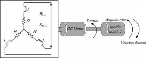
There are three phase windings on the stator and permanent magnet rotor of a three phase BLDCM as shown in Figure 1. Because the machine back EMF is trapezoidal it differs from the Permanent Magnet Synchronous Motor, which has a circular back EMF. In certain cases, it's not clear which models should be utilized when a specific situation arises. Except for its lack of damper windings and the use of permanent magnets as excitation instead of field windings, the BLDCM is remarkably similar to a typical wound-rotor-synchronous machine [6-10].
Figure 1. Equivalent circuit of BLDCM
As the rotor moves, it induces voltage into the stator winding, which in turn affects torque in BLDC motors. Assuming the ideal design is achieved with rectangular stator current and trapezoidal back-EMF waveforms, the theoretical torque of BLDC motors will be constant. Because of emf waveform imperfections, current ripple, and phase current commutation, there is a lot of torque jitter in reality. PWM or hysteresis control is responsible for the current ripple. Design considerations may lead to changes in the shape of slots, skews and magnets that affect the voltage waveform of BLDC motors. Since the real value may differ from what is predicted by a simulation, an error may arise. There are a number of simulation models for the examination of BLDC motors [11-14]. Another model features a true back-EMF waveform with a shape that is very similar to a sinusoidal shape, which is one of the models under consideration.
Because the trapezoidal nature of the stator winding and rotor magnets' location must be detected at every second to activate specific switches in ON and OFF states, BLDC models are difficult for any users. Using a Hall Effect sensor, the ON/OFF PWM signals are provided with information about the rotor's magnets and the related decoding signals. Actuator models must have a dynamic performance system with reduced ripple harmonics and better effectiveness [15-22].
In the MATLAB/ SIMULINK environment, the suggested BLDC motor modelling is performed. In order to achieve desired system performance, a BLDC motor, or actuator, must be designed using MATLAB's powerful system modelling capabilities [23-28]. Modeling BLDC motors in MATLAB is presented in this study using three methods: the state transfer equations, the transfer functions, and the state space model. Inverter, motor, and decoder modelling are all included in the modelling of a BLDC motor.
The remainder of this work is arranged as follows. In Section 2, we provide a short overview of BLDC Motors. In Section 3, an objective evaluation of BLDC motors is provided. Concluding remarks of the paper given in section 4.
2.1 Principle &architecture of BLDCM
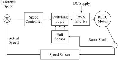
Brushless direct current motors (BLDCM) are a kind of synchronous motor in which the coil is made of permanent magnets. These are the motors that do not have brushes or commutators to allow for the passage of current or the commutation of the motor. It's for this reason that these kinds of motors are sometimes referred to as electronically commutated motors. In fact, they are not controlled directly but rather via an associated electrical converter that turns the phases of BLDCM ON/OFF in response to the position of the rotor [29, 30]. 1200 conductivity mode and 1800 conductivity mode are selectable through the switches located inside the electrical converter. Figure 2 depicts a block design of the open loop BLDCM.
In the on top of diagram shown, the pulses area unit generated from the Microcontroller that is given to the gate port of three section electrical converter through the gate driver circuit. The electrical converter is battery-powered from a DC supply of 12V. The electrical converter drives the motor. The speed of the motor is varied by varied the voltage to the motor.
Eq. (1) can be used to describe the BLDC motor terminal voltage equation, which can then be calculated as state space model equations and simulated using the MATLAB toolbox.
$\mathrm{V}_{a}=\mathrm{R}_{a} \mathrm{I}_{a}+\mathrm{L}_{a} \mathrm{di}_{a} / \mathrm{dt}+\mathrm{M}_{a c} \mathrm{di}_{b} / \mathrm{dt}+\mathrm{M}_{b c} \mathrm{di}_{c} / \mathrm{dt}+\mathrm{e}_{a}$
$\mathrm{~V}_{b}=\mathrm{R}_{b} \mathrm{I}_{b}+\mathrm{L}_{b} \mathrm{di}_{b} / \mathrm{dt}+\mathrm{M}_{a c} \mathrm{di}_{a} / \mathrm{dt}+\mathrm{M}_{b c} \mathrm{di}_{c} / \mathrm{dt}+\mathrm{e}_{b}$
$\mathrm{~V}_{c}=\mathrm{R}_{c} \mathrm{I}_{c}+\mathrm{L}_{c} \mathrm{di}_{c} / \mathrm{dt}+\mathrm{M}_{a c} \mathrm{di}_{b} / \mathrm{dt}+\mathrm{M}_{b c} \mathrm{di}_{a} / \mathrm{dt}+\mathrm{e}_{c}$ (1)
where, $\mathrm{R}_{a-b}$ is the resistance per phase, which is the same for all phases. $\mathrm{L}_{a-b}$ is the inductance per phase that is equal to the total of all phases. Mutual inductance exists between $M_{a c}$ and $\mathrm{M}_{b c}$. Net impact value will be zero in the case of a BLDC motor. The variables $\mathrm{i}_{a}, \mathrm{i}_{b}$, and $\mathrm{i}_{c}$ represent the current and phase of the stator. The phase voltages of the winding are represented by the letters $\mathrm{V}_{a}, \mathrm{~V}_{b}$, and $\mathrm{V}_{c} . \mathrm{e}_{a}, \mathrm{e}_{b}$, and $\mathrm{e}_{c}$ represents the back-EMF.
Figure 2. Block diagram of open loop BLDCM
Stator resistance and inductance, and the back EMF constant of the motor are all factors that influence motor control responsiveness. For maximal overshoot, an unsteady condition with increased transient reaction and reduced time response of the control actuation system, look to the motor settings.
As an IGBT-based inverter circuit, the BLDC Motor Driver creates three-phase voltage to power BLDC motors using a switching PWM signal as input. Using three hall sensors, the controller is able to monitor the rotor's position at 120 electrical degrees. For six input combinations, three hall sensors with eight combinations provide hall signals with 120-electrical-degree sensor phasing.
A quadrature encoder is used to obtain rotor position information from the BLDC motor as a feedback to the controller while modelling the control actuation system. The BLDC motor shaft is connected to the shaft encoder model subsystem. There will be an output from this encoder block that includes the rotor speed and phase shifting location, as well as a pulse frequency and velocity. The motor's speed, location, and direction may all be calculated using the shaft encoder pulses. The whole calculation is based on a MATLAB Simscape model and a triggered subsystem for calculating information from an encoder's square wave [21].
2.2 Mathematical model of BLDCM in MATLAB/ SIMULINK
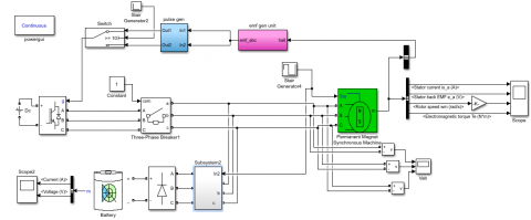
In an open loop control of BLDCM, the speed is management led solely through the control of voltage. Diagram shown in Figure 3 represents the model of the open loop BLDCM in MATLAB/SIMULINK. The pulses area unit generated through a PWM generator of fifty, hour and seventieth duty cycle. These area unit given as inputs to the bottom port of the IGBT three section electrical converter [31, 32]. The input supply to the electrical converter is 12V. Another advantage of the BLDCM is that they can operate for low voltages such as 12v or 24v.
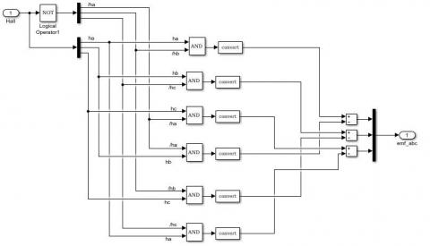
The BLDCM is driven by the PWM pulses. The system for generation of PWM pulses area unit shown in Figure 4 that generate four-hundredth, five hundredth and hour of the duty cycles.
When it comes to speed and torque management, the proportional integral PI controller is used. Kp and Ki factors are evaluated using a modified deferent assessment. In fact, two levels of PI controller are required to complete this job successfully. To begin, we have a speed controller, which compares a predetermined reference speed to the motor's actual output speed. As a current controller block, the second stage "torque controller" receives this torque set point. To adjust torque, the motor current is used, and this leads to a four-stage current controller. The first step is to transform the reference torque that has been selected into a reference maximum current value. The currents in the motor coils are assumed to be pure square waves in this procedure. In terms of measuring magnetic fields, the Hall Effect is the most frequent way, and the Hall Effect sensor is well-known and extensively used. The second step is a sensor for the block EMF (electromagnetic field). It is used in order to determine the precise location of the rotor. When the motor rotor is in motion mode, the sensor's output comprises three voltage levels (negative, zero, positive), which indicate real current injections into the three phase coils of the motor to achieve the desired high density output torque. The current regulator is in the third step of the process. To be more precise, it compares the converted reference torque (reference currents) with the actual torque produced by the motor. This is the last level, which is the switching control. A three-level inverter with pulses generated by this component is controlled by this component to the value stated in the reference section.
Figure 3. Open loop simulation model of BLDCM block diagram
Figure 4. Subsystem block for decoder unit
2.3 Hardware implementation of BLDCM
The hardware implementation of open loop management of BLDCM that in the main consists of BLDCM, IGBT electrical converter, reference current and supported their own characteristic BLDCM.
The specifications of the motor are listed below in Table 1.
Table 1. Specifications of BLDCM
|
S. No |
Description |
Value |
Unit |
|
1 |
Supply voltage |
110 |
V |
|
2 |
Rated speed |
200 |
Rpm |
|
3 |
Torque constant |
1.4 |
N-m |
|
4 |
Sudden load |
1 |
N-m |
|
5 |
Stator phase resistance Rs |
2.8750 |
Ohm |
|
6 |
Stator phase inductances Ls |
8.5e-3 |
H |
|
7 |
Flux linkage established by magnets |
0.175 |
V.s |
|
8 |
Back EMF flat area |
120 |
Degrees |
|
9 |
Inertia, friction factor and pole pair |
0.8e-3, 1e-3, 4 |
J(kg.m2); F (N.m.s), p |
|
10 |
Initial conditions |
0,0,0,0 |
Wm(rad/s), theta m(deg), ia,Ib(A) |
|
11 |
Simulation time |
3 |
sec |
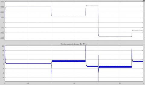
3.1 Four Quadrant operation torque and speed responses
The Figures 5 and 6 show Four Quadrant operation torque and speed responses at totally different load conditions. In the first instance, the motor is operating at no load, which means that the applied load torsion is kept at zero; the reference speed is given, and as a result, the real speed may be determined. In the second instance, the load torsion is applied at a variety of various times, and the performance factors are determined as a result of this. Because it works in all four quadrants [24, 25], the load and, as a result, the reference speed may be changed, and the reaction of the machine can be determined as a result.
At load torque 3N-m
Figure 5. Four Quadrant operation torque and speed responses
At load torque 10N-m
Figure 6. Four Quadrant operation torque and speed responses
3.2 Three phase line to line voltage responses
The line to line voltages of three phase input to the BLDCM is obtained from inverter is shown Figure 7.
Figure 7. Three phase line to line voltage responses
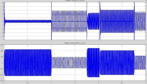
3.3 Stator current and Back EMF responses
Figure 8 depicts the stator current and the back EMF produced by the motor, which are shown individually. An obvious spike can be seen in the stator currents of the three phases [33-38]. These are the points in time at which the speed of the BLDCM changes from one state to another.
Figure 8. Stator current and Back Emf wave form
3.4 The output characteristic results of BLDCM
The observations of the BLDCM are taken from Table 2. The torque applied is positive from the time of start up to 1.0 s. In other words, the machine is working in the first quadrant, forward driving, and a negative torque is supplied at the period of 1.75 s. This indicates that an abrupt halt has been imposed. This is the second quadrant of operation, or forward braking, and occurs at 2.0 s. The motor is pushed to spin in the opposite direction, and the applied torque stays negative throughout this time period; this is the second quadrant of operation, or forward braking. Because both torque and speed are negative, the motor is operating in the third reverse motoring quadrant; however, at 2.75 s, the load torque applied is positive, indicating that the motor is operating in the fourth reverse motoring quadrant; and a sudden brake is applied, causing the rotor speed to drop to zero rpm, indicating that the motor is operating in the fourth reverse braking quadrant of speed torque characteristics.
Table 2. Characteristic results of BLDCM
|
|
Motoring mode |
||||
|
No load motoring mode 0 to 1 sec |
Load motoring mode 1 to 1.75 sec |
Forward braking mode 1.75 to 2 sec |
Reverse motoring mode 2 to 2.75 sec |
Reverse Braking mode 2.75 to 3 sec |
|
|
Description |
Motoring mode |
Motoring mode |
Forward Braking mode |
Reverse Motoring mode |
Reverse braking mode |
|
Stator current ia(A) |
Current is initially 25.6 A then remains 0.31A |
Current is 2.08 A |
Current is 1.62 A |
Current is 2.18 A |
Remains 1.96 |
|
Rotor speed (rpm) |
Speed initially accelerating and settles at 3125 rpm |
Speed remains 840 rpm |
Speed remains 3291 rpm and comes to stand still at 2 sec |
Speed initially accelerating and settles at 2780 rpm (reverse direction) |
settles at 1577 rpm (reverse direction) |
|
Electromagnetic torque (N-m) |
remains zero |
Torque is 10 N-m |
Torque is -10 N-m |
Torque is -10 N-m |
Torque is 10 N-m |
|
Back emf Ea (v) |
Increases initially and settles at 160 V |
Remains constant at 64.8V |
Remains constant at 173.2V |
Remains constant at 145V |
Remains at 85.5 V |
The BLDC motor drive system was modelled using a variety of techniques in this work. The transient condition and the nonlinearity of the motor cannot be accurately predicted by linear modelling. Conventional control approaches, sensor less schemes, and high-speed operation may all be implemented utilizing the field-oriented method. It is, nevertheless, necessary to employ a multiple reference frame because of the trapezoidal voltage waveforms and quasi square current waveforms. The BLDCM area unit thought of in most of the applications thanks to their less weight, additional speed and additional power, low value and less maintenance. During this research, associate in open loop speed management of three sections BLDCM was exhausted MATLAB/SIMULINK and Hardware. The speed comparison was in serious trouble the simulated style and therefore the hardware. it had been seen from the comparison that the speed will increase once the duty cycle will increase (increase in voltage) and speed decreases once the duty cycle decreases (decrease in voltage). BLDCM that area unit stepper motors are employed in open loop speed management for the applying like robotic arm movement for industrial application, is employed in house for projection of satellite panels, is used for actuators in part applications, feed drives for the CNC machine and etc. It is recommended that numerical modelling methods such as finite element be used in conjunction with the proposed modelling method in order to improve the accuracy of the modelling of BLDC motor drive, such as taking into account non-ideal back-EMF voltage waveforms and torque ripple due to cogging effect.
[1] SudhanshuMitra, R., Nayak, S., Prakash, R. (2015). Modeling and simulation of BLDC motor using Matlab/Simulink environment. International Research Journal of Engineering and Technology (IRJET), 2(8): 199-203.
[2] Raghu, T., Sekhar, S.C., Rao, J.S. (2012). SEPIC converter based-drive for unipolar BLDC motor. International Journal of Electrical and Computer Engineering (IJECE), 2(2): 159-165. https://doi.org/10.11591/ijece.v2i2.306
[3] Niasar, A.H., Vahedi, A., Moghbeli, H. (2007). Torque control of brushless DC motor drive based on DSP technology. In 2007 International Conference on Electrical Machines and Systems (ICEMS), pp. 524-528. https://doi.org/10.1109/ICEMS12746.2007.4412018
[4] Matsui, N. (1996). Sensorless PM brushless DC motor drives. IEEE Transactions on Industrial Electronics, 43(2): 300-308. https://doi.org/10.1109/41.491354
[5] Johnson, J.P., Ehsani, M., Guzelgunler, Y. (1999). Review of sensorless methods for brushless DC. In Conference Record of the 1999 IEEE Industry Applications Conference. Thirty-Forth IAS Annual Meeting (Cat. No. 99CH36370), pp. 143-150. https://doi.org/10.1109/IAS.1999.799944
[6] Nasar, S.A., Boldea, I., Unnewehr, L.E. (1993). Permanent Magnet Reluctance & Self Synchronous Motors. CRC-Press.
[7] Pillay, P., Krishnan, R. (1989). Modeling, simulation, and analysis of permanent-magnet motor drives. I. The permanent-magnet synchronous motor drive. IEEE Transactions on Industry Applications, 25(2): 265-273. https://doi.org/10.1109/28.25541
[8] Qinghua, L., Jabbar, M.A., Khambadkone, A.M. (2002). Design optimisation of wide-speed permanent magnet synchronous motors. In 2002 International Conference on Power Electronics, Machines and Drives (Conf. Publ. No. 487), pp. 404-408. https://doi.org/10.1049/cp:20020151
[9] Lee, B.K., Ehsani, M. (2003). Advanced simulation model for brushless dc motor drives. Electric Power Components and Systems, 31(9): 841-868. https://doi.org/10.1080/15325000390227191
[10] Demirbas, S., Gencer, C. (2004). Matlab/Simulink based modeling and simulation of permanent magnet synchronous motor drive. In Proc. 2. International Conference on Technical and Physical Problems in Power Engineering, Tabriz, Iran, pp. 645-649.
[11] Rani, B.I., Tom, A.M. (2008). Dynamic simulation of brushless DC drive considering phase commutation and backemf waveform for electromechanical actuator. In TENCON 2008-2008 IEEE Region 10 Conference, pp. 1-6. https://doi.org/10.1109/TENCON.2008.4766608
[12] Yedamale, P. (2003). Brushless DC (BLDC) motor fundamentals. Microchip Technology Inc, 20(1): 3-15.
[13] Grasblum, P. Sensorless BLDC motor control using an 8-bit MCU. Freescale. https://www.yumpu.com/en/document/read/19687079/bldc-motor-control-using-8-bit-mcu-cost-effective-sensorless-, accessed on 12 Apr. 2021.
[14] Jeon, Y.S., Mok, H.S., Choe, G.H., Kim, D.K., Ryu, J.S. (2000). A new simulation model of BLDC motor with real back EMF waveform. In COMPEL 2000. 7th Workshop on Computers in Power Electronics. Proceedings (Cat. No. 00TH8535), pp. 217-220. https://doi.org/10.1109/CIPE.2000.904719
[15] Hong, W., Lee, W., Lee, B.K. (2007). Dynamic simulation of brushless DC motor drives considering phase commutation for automotive applications. In 2007 IEEE International Electric Machines & Drives Conference, pp. 1377-1383. https://doi.org/10.1109/IEMDC.2007.383630
[16] Laczko, A.A., Zaharia, M.V., Radulescu, M.M., Brisset, S. (2015). Modeling and simulation of a brushless DC permanent-magnet generator-based wind energy conversion system. In 2015 Tenth International Conference on Ecological Vehicles and Renewable Energies (EVER), pp. 1-7. https://doi.org/10.1109/EVER.2015.7113021
[17] Gebauer, J., Fojtík, D., Podešva, P. (2015). Modeling of the electronic variable pitch drive. In Proceedings of the 2015 16th International Carpathian Control Conference (ICCC), pp. 138-141. https://doi.org/10.1109/CarpathianCC.2015.7145062
[18] Pan, S., Edelberg, K., Hedrick, J.K. (2014). Discrete adaptive sliding control of automotive powertrains. In 2014 American Control Conference, pp. 202-207. https://doi.org/10.1109/ACC.2014.6859146
[19] Shu, Y., Li, H., Xu, L.M., Wu, Q. (2007). A rapid development method on brushless DC motor controller. In 2007 IEEE International Symposium on Industrial Electronics, pp. 3293-3297. https://doi.org/10.1109/ISIE.2007.4375143
[20] Chen, W.C., Cheng, M.Y., Kuo, T.H., Li, C.L. (2011). Development of intellectual property for brushless DC motor drives. In 2011 IEEE Symposium on Industrial Electronics and Applications, pp. 499-504. https://doi.org/10.1109/ISIEA.2011.6108762
[21] Awaze, S.K. (2013). Four quadrant operation of BLDC motor in MATLAB/SIMULINK. In 2013 5th International Conference and Computational Intelligence and Communication Networks, pp. 569-573. https://doi.org/10.1109/CICN.2013.124
[22] Vinatha, U., Pola, S., Vittal, K.P. (2008). Simulation of four quadrant operation & speed control of BLDC motor on MATLAB/SIMULINK. In TENCON 2008-2008 IEEE Region 10 Conference, pp. 1-6. https://doi.org/10.1109/TENCON.2008.4766449
[23] Tsai, M.F., Quy, T.P., Wu, B.F., Tseng, C.S. (2011). Model construction and verification of a BLDC motor using MATLAB/SIMULINK and FPGA control. In 2011 6th IEEE Conference on Industrial Electronics and Applications, pp. 1797-1802. https://doi.org/10.1109/ICIEA.2011.5975884
[24] Fahimi, B., Emadi, A., Sepe, R.B. (2005). Four-quadrant position sensorless control in SRM drives over the entire speed range. IEEE Transactions on Power Electronics, 20(1): 154-163. https://doi.org/10.1109/TPEL.2004.839817
[25] Muller, S., Deicke, M., De Doncker, R.W. (2002). Doubly fed induction generator systems for wind turbines. IEEE Industry Applications Magazine, 8(3): 26-33. https://doi.org/10.1109/2943.999610
[26] Zhong, L., Rahman, M.F., Hu, W.Y., Lim, K.W. (1997). Analysis of direct torque control in permanent magnet synchronous motor drives. IEEE Transactions on Power Electronics, 12(3): 528-536. https://doi.org/10.1109/63.575680
[27] Tashakori, A., Ektesabi, M., Hosseinzadeh, N. (2011). Modeling of BLDC motor with ideal back-emf for automotive applications. In Proceedings of the World Congress on Engineering, London, UK.
[28] Gebauer, J., Fojtík, D., Podešva, P. (2015). Modeling of the electronic variable pitch drive. In Proceedings of the 2015 16th International Carpathian Control Conference (ICCC), pp. 138-141. https://doi.org/10.1109/CarpathianCC.2015.7145062
[29] Copeland, B.R. (2008). The design of PID controllers using Ziegler Nichols tuning. http://educypedia.karadimov.info/library/Ziegler_Nichols.pdf.
[30] Pan, S., Edelberg, K., Hedrick, J.K. (2014). Discrete adaptive sliding control of automotive powertrains. In 2014 American Control Conference, pp. 202-207. https://doi.org/10.1109/ACC.2014.6859146
[31] Tibor, B., Fedak, V., Durovský, F. (2011). Modeling and simulation of the BLDC motor in MATLAB GUI. In 2011 IEEE International Symposium on Industrial Electronics, pp. 1403-1407. https://doi.org/10.1109/ISIE.2011.5984365
[32] Murali, M., Arulmozhiyal, R. (2021). Investigation on modeling and simulation BLDC motor fed universal actuation system. Revista Internacional de Métodos Numéricos para Cálculo y Diseño en Ingeniería, 37(1).
[33] Chhlonh, C., Riawan, D.C., Suryoatmojo, H. (2019). Modeling and simulation of independent speed steering control for front in-wheel in EV using BLDC motor in MATLAB GUI. In 2019 International Seminar on Intelligent Technology and Its Applications (ISITIA), pp. 270-275. https://doi.org/10.1109/ISITIA.2019.8937199
[34] Alsayid, B., Salah, W.A., Alawneh, Y. (2019). Modelling of sensored speed control of BLDC motor using MATLAB/SIMULINK. International Journal of Electrical and Computer Engineering, 9(5): 3333. http://doi.org/10.11591/ijece.v9i5.pp3333-3343
[35] Hameed, H.S. (2018). Brushless DC motor controller design using MATLAB applications. In 2018 1st International Scientific Conference of Engineering Sciences-3rd Scientific Conference of Engineering Science (ISCES), pp. 44-49. https://doi.org/10.1109/ISCES.2018.8340526
[36] Liu, X., Fan, X., Wang, F., Zhao, Z. (2018). The BLDC simulation study of electronic water pump based on MATLAB/Simulink. Recent Patents on Mechanical Engineering, 11(3): 251-259. https://doi.org/10.2174/2212797611666180810150903
[37] Rawat, A., Bilal, M., Azeem, M. F. (2020). PI controller based performance analysis of brushless DC motor, utilizing MATLAB Simulink environment. Journal of Scientific Research and Reports, 26(2): 38-43. https://doi.org/10.9734/jsrr/2020/v26i230222
[38] Ravindran, A., Kumar, A.B. (2017). Solar powered BLDC motor drive using LUO converter. In 2017 IEEE International Conference on Power, Control, Signals and Instrumentation Engineering (ICPCSI), pp. 1030-1035. IEEE. https://doi.org/10.1109/ICPCSI.2017.8391866