Abdelghani Aib | Djalal Eddine Khodja | Salim Chakroune* | Loutfi Benyettou
OPEN ACCESS
This work is part of the study and implementation of a fuzzy PWM control structure (fuzzy pulse width modulation) of an induction machine (MAS) on a circuit-based platform reconfigurable FPGA type. We first presented a strategy for the hardware implementation of a fuzzy inference system on a programmable logic circuit of FPGA type, through the hardware description language (VHDL) and Xilinx generator system (XSG). Secondly we proposed Fuzzy-PWM architecture for the improvement of response time of an asynchronous machine (MAS) and finally we validate the proposed hardware co-simulation architecture in real time on the ML402 development kit (based on FPGA Xilinx Virtex-4) and Simulink / Matlab.
pulse width modulation, fuzzy control, ML402, hardware co-simulation, induction machine control, Xilinx generator system
The induction machine, by its construction, is the most robust and cheapest machine on the market. The progress made in control and the considerable technological advances, both in the field of power electronics and microelectronics, have made possible the implementation of powerful controls of this machine making it a wonderful competitor in the sectors of variable speed and rapid torque control [1-4].
In recent decades, rather laborious controls have been developed to perform asynchronous machine control using PWM pulse width modulation techniques [5-8]. This advance is mainly due to the evolution of microelectronics such as ASICs, microprocessors and programmable logic circuits [9-11] that allows complex algorithms to implement the commands of the asynchronous machine [12-14]. In addition, the integration of artificial intelligence techniques to improve the performance of commands is increasingly used [15, 16]. In [1] the author uses genetic algorithms to identify dynamic model parameters of the asynchronous machine and implement controllers, based on fuzzy logic and neural networks within a vector control by rotor field orientation. A new control based on adaptive fuzzy controllers has been proposed by Salim and Thierry [17] fuzzy controllers are implemented for the control of MAS through voltage inverters [18, 19].
The implementation of artificial intelligence techniques on programmable logic circuits FPGA for the control of electrical drive systems such as MAS reduces the computation time generated by the complex algorithms of these techniques [20]. Also make them more suitable applications in real time, methodologies for the implementation of a fuzzy controller on FPGA [21, 22]. An implementation of optimized approximate sigmoid function on FPGA circuit to use in ANN for MAS control and monitoring is detailed in ref. [23].
The objective of this work is the validation of a hardware architecture that allows the acceleration of the response time of an asynchronous machine controlled by Sinus triangle PWM. Through a fuzzy inference system implemented on the ML402 platform with a Xilinx Virtex-4 FPGA, aiming at improving computing time and optimizing hardware resources used by an optimized architecture described in hardware description language VHDL and Xilinx system generator. The development, simulation, synthesis and hardware co-simulation steps are performed using the Xilinx system generator tool on Simulink / Matlab.
The hardware implementation of a fuzzy inference system consists in implementing the three phases of fuzzy logic regulation: Fuzzification, Fuzzy Inference and Defuzzification (Figure 1).
Figure 1. The components of a fuzzy inference system
2.1 Fuzzification
Fuzzy logic systems deal with fuzzy input variables and provide results on output variables that are themselves fuzzy. Fuzzification is the step that consists in the fuzzy quantification of the real values of a variable.
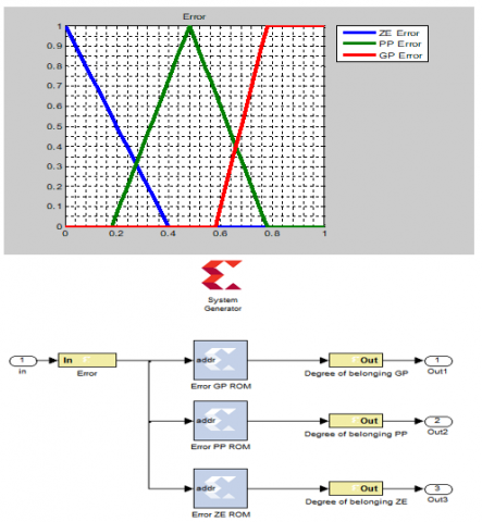
Figure 2 shows an example of implementation on "Xilinx System Generator" of a linguistic variable called "Error" that takes 3 linguistic values "GP" (Grand Positive), "PP" (Small Positive) and "ZE" (Zero), discretized on a universe of standardized speech [0, 1]:
Figure 2. Implementing a linguistic variable on XSG
The hardware resources needed to implement this linguistic variable estimated by the Xilinx Resource Estimator tool are shown in Figure 3:
Figure 3. The hardware's consumed by a variable with three linguistic values
2.2 Rule inference and rule evaluation
Fuzzy logic systems use expertise expressed in the form of a rule base of the type: If...Then...
If $(X 1$ is $A 1)$ and $(X 2$ is $A 2)$ Then $(Y$ is $B 1)$
If $(X 1$ is $A 1)$ Or $(X 2$ is $A 2)$ Then $(Y$ is $B 2)$
In this work the operations and/or logic are done by the operators of Zadeh MIN/MAX, moreover the fuzzy implications and the Aggregation of the rules are made by the method of Mamdani (min/max).
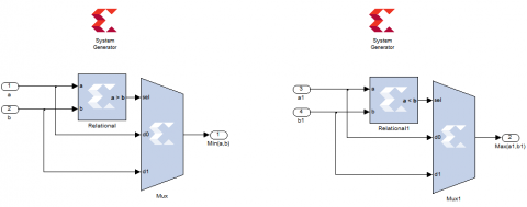
The hardware implementation on "Xilinx System Generator" of the two-input (min/max) operators is done by a comparator and a 2-1 multiplexer.
Figure 4 shows the wiring of the min/max functions:
Figure 4. The implementation of Min and Max functions on XSG
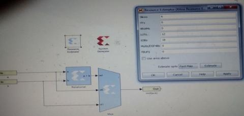
Figure 5. The hardware consumed by a Min operator with two entrances
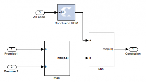
For operators (min / max) who have more than two inputs, two-input operators (min/max) are used for the implementation of these operators. For example, for implementation an operator (Min) with three entries, two operators (Min) with two entries are used:
Figure 6. The implementation of a Min function with 3 inputs
2.2.1 Implementation of a rule with conjunction AND of the form
If (Premise1) and (Premise2) then (Conclusion)
Figure 7. Implementing a rule with conjunction AND
2.2.2 Implementing a rule with OR conjunction
If (Premise1) Or (Premise2) then (Conclusion)
Figure 8. Implementing a rule with OR conjunction
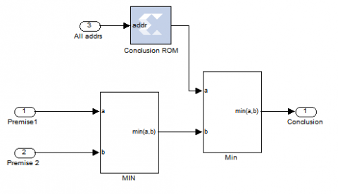
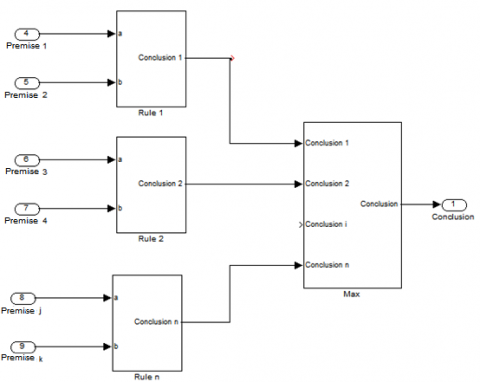
2.2.3 Composition of the rules
If several rules can be activated simultaneously and recommend actions with different degrees of validity on the same output. Rules are considered to be linked by an OR operator.
Figure 9. Implementing a rule composition for an output
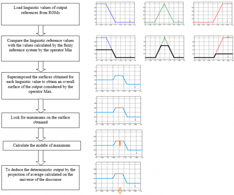
Defuzzification is the method of converting output linguistic values obtained into precise values. For the hardware implementation we always try to avoid expensive arithmetic operations from the point of view of hardware resource consumption such as multiplication and division, for this we use the method of defuzzification middle of maximum (MM) for the conversion of linguistic values output obtained in precise values.
Figure 10. Descriptive flowchart of the middle of maximum method used for defuzzification
Figure 10 shows a description of the VHDL code used to implement the middle of maximum (MM) defuzzification method.
3.1 Issue and proposed Fuzzy-STPWM architecture
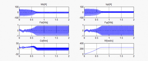
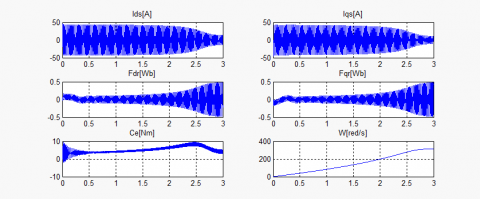
By observing the response time of an asynchronous machine controlled by a Sinus -Triangle PWM control, we see that the response time is very short for small references and increases dramatically for higher references, for example to reach 30 red / s it takes 0.4s on the other hand for 50 red/ s it takes 2.5 s (> 6 * 0.4).
Figure 11. The responses of induction machine for a PWM control with variable references
The question is: can we take advantage of the speed of small references to improve the response time of higher references?
Our architecture based on the affirmation of the previous question, and our proposed solution, a progressive start of the machine: we start with small references and each time we reach the steady state, we go up to the next reference until the reference desired. For that it is necessary:
1. A mechanism for generating Sinus -Triangle PWM signals with variable references in real time.
2. A detection and decision tool to switch between the different references.
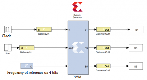
For the first constraint, a Sinus -Triangle PWM signal generator has been implemented for variable references on a programmable logic circuit of the FPGA type.
For the second constraint: we used a fuzzy inference mechanism for the detection of steady state (we must detect the steady state as soon as possible to save time) and for the generation of references (three references in our case).
Figure 12. The PWM signal generator architecture implemented on FPGA
The first input of fuzzy controller is the error between the desired reference speed and the current speed of the machine, the error fuzzifying with a linguistic variable called "Error" that can take the following linguistic values: Z (null or Zero), PP (Positive Small) and GP (Positive Great).
Figure 13. Proposed fuzzy logic controller
Figure 14. The linguistic values of the linguistic variable "Error"
Figure 15. The linguistic values of the linguistic variable "De"
The second input of our fuzzy controller is the drive of the error and fuzzify by a linguistic variable called "De" that can take the following linguistic values: Z (Zero) indicates that the error is constant ie the steady state is reached and N (Negative) indicates that the error is decreasing.
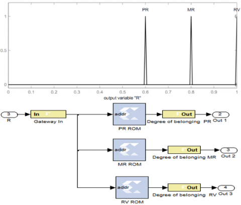
The output of fuzzy controller is the progressive references proposed for starting the machine. It is fuzzifier by a linguistic variable called "R" can take the following linguistic values: PR (Small Reference), MR (Average Reference) and RV (the desired reference).
The fuzzy inference input/output can be summarized in the Table 1:
Table 1. The input/output inference of fuzzy controller
|
De Error |
N |
Z |
|
GP |
PR |
MR |
|
PP |
MR |
RV |
|
Z |
RV |
RV |
3.2 Hardware description of the fuzzy controller
In this work, the tool used for the hardware description is XSG (Xilinx System Generator) under the Matlab/Simulink environment. Unlike hardware description languages (HDL), the XSG is more useful for fast design and testing of a control algorithm. With the link between the Matlab/Simulink environment and Xilinx ISE, the XSG automatically performs all the necessary design steps: description, synchronous analysis, generation of HDL and bit stream files, and finally the actual implementation in the target device. The hardware description of fuzzy controller implemented with XSG is shown in Figure 17.
Figure 18 shows the fuzzy PWM "Sinus-triangle" (FUZZY STPWM) control platform implemented for the development of a test bench dedicated to the control of a three-phase inverter.
Figure 16. Linguistic values of the linguistic variable "R"
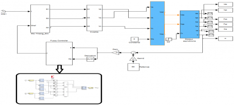
Figure 17. Hardware description of the fuzzy controller implemented with XSG
Figure 18. The hardware architecture of FUZZY STPWM
4.1 The synthesis RTL
We have synthesized the architecture described for the implementation of the fuzzy controller on the Xilinx Virtex-4 map. The synthesis result of our architecture obtained by XSG presented in Table 2.
Note that the proposed architecture optimizes use the hardware resources of the FPGA card (10% of Slices and 7% of LUTs). Moreover this architecture considerably reduces the logical components to use, compared to the complexity of a computer system Fuzzy inference.
4.2 High level simulation
Firstly, we simulated the classical PWM control and fuzzy PWM of the asynchronous motor under Matlab/Simulink and XSG with the test bench dedicated to the control of a following asynchronous motor.
The simulation results of the standard PWM and fuzzy PWM commands of the asynchronous motor for reference of 40 and 50 red/s is presented in Figures 20, 21, 22 and 23.
We can notice that the response time is largely reduced by Fuzzy PWM for both references.
Table 2. Summary result for the proposed fuzzy controller
|
Target Device: xc4vsx35-10ff668 |
|||
|
Logic Utilization |
Used |
Available |
Utilization |
|
Number of Slice Flip Flops |
1,302 |
30,720 |
4% |
|
Number of occupied Slices |
1.675 |
15,360 |
10% |
|
Total Number of 4 input LUTs |
2.269 |
30,720 |
7% |
|
Number of bonded IOBs |
58 |
448 |
12% |
|
Number of FIFO16/RAMB16s |
12 |
192 |
6% |
|
Number of BUFG/BUFGCTRLs |
7 |
32 |
21% |
Figure 19. Simulated PWM simulation test bench under Matlab/Simulink and XSG
Figure 20. Responses of induction machine control with PWM 40 red/s
Figure 21. Responses of induction machine control with Fuzzy PWM 40 red/s
Figure 22. Responses of induction machine control with PWM 50 red/s
Figure 23. Responses of induction machine control with Fuzzy PWM 50 red/s
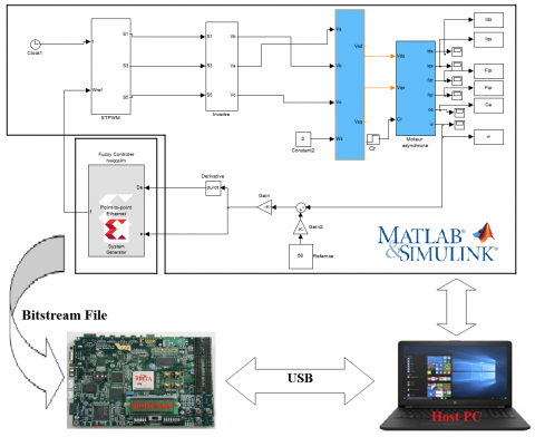
Figure 24. On-line Hardware in the Loop validation of Fuzzy Controller of induction machine control
Figure 25. Hardware in the Loop validation of Fuzzy PWM for 40 red/s
Figure 26. On-line Hardware in the Loop validation of based Fuzzy PWM control for 50 red/s
4.3 Validation of the hardware architecture of the proposed fuzzy controller
After a simulation step, the proposed hardware architecture of the fuzzy controller was validated by co-simulation hardware on the ML402 target device with a VIRTEX4 FPGA chip.
The following figure shows the principle of validation of the architecture proposed by hardware co-simulation:
The results obtained in co-simulation hardware and by comparison with those obtained by the simulation phase clearly show the accuracy of the model developed in terms of a good compliance of the results.
In this article, we have shown the relevance of using FPGAs in the field of digital control and in particular the control of a MAS via the PWM controls "Sinus-triangle" through a fuzzy controller. Indeed, we developed, validated and synthesized hardware architecture for the implementation of a fuzzy inference system on FPGA and then we physically implanted the fuzzy controller synthesized on an FPGA circuit to validate the proposed architecture on a bench of tests dedicated to the fuzzy MLI control of an asynchronous motor. Practically, we have used the Xilinx ML402 and XSG prototyping platform under Matlab/Simulink for hardware co-simulation of the fuzzy PWM control of an asynchronous motor. The summary results show that the hardware resources consumed do not exceed 10%, which offers the possibility of implementing other algorithms in the same domain and gives vast perspectives of this work.
As a forthcoming application, we will take advantage of the implementation achieved in this work in order to use the proposed fuzzy controller hardware architecture for the implementation of fuzzy-DTC on FPGA.
This work was supported by Electrical Engineering Laboratory (LGE) at the University of Mohamed Boudiaf- M’sila, (Algeria) and Signals & Systems Laboratory, Institute of Electrical and Electronic Engineering Boumerdes University, (Algeria). We like to thank Dr. Djalal Eddine Khodja and Dr. Salim Chakroune for their help in the preparation of this paper.
[1] Alexandre, B., Nyobe, Y., Jean, M., Leandre, N.N., Laure, M.M. (2018). Fault diagnosis of an induction motor based on fuzzy logic, artificial neural network and hybrid system. International Journal of Control Science and Engineering, 8(2): 42-51. https://doi.org/10.5923/j.control.20180802.03
[2] Nasir Uddin, M., Hafeez, M. (2010). FLC-based DTC scheme to improve the dynamic performance of an IM drive. IEEE Transactions on Industry Applications, 48(2): 1-7. https://doi.org/10.1109/IAS.2010.5614089
[3] Valantina, S., Suresh, L.P. (2013). Investigation of FPGA based PWM control technique for AC motors. International Journal of Power Electronics and Drive System (IJPEDS), 3(2): 193-199. https://doi.org/10.11591/ijpeds.v3i2.2895
[4] Nabil, F., Talib, M., Ibrahim, Z., Abdullah, Q., Ömer, A., Zulhani, R., Auzani, J., Jurifa, M. (2020). Analysis and investigation of different advanced control strategies for high-performance induction motor drives. TELKOMNIKA, 18(6): 3303-3314. https://doi.org/10.12928/telkomnika.v18i6.15342
[5] Narayana, G., Ranganathan, V.T. (2002). Two novel synchronized bus-clamping PWM strategies based on space vector approach for high power drives. IEEE Transactions on Industry Applications. 17(1): 84-93. https://doi.org/10.1109/63.988673
[6] Hakan, A., Resul, C., Mehmet, U., Besir, D. (2018). Robust control of current controlled PWM rectifiers using type-2 fuzzy neural networks for unity power factor operation. J Electr Eng Technol, 132)): 822-828. http://doi.org/10.5370/JEET.2018.13.2.822
[7] Jasinski, M., Liserre, M., Blaabjerg, F., Cichowlas, M. (2002). Fuzzy logic current controller for PWM rectifiers. IEEE Conference of the Industrial Electronics Society. IECON 02, Sevilla, Spain. https://doi.org/10.1109/IECON.2002.1185463.
[8] Hau Huu, V., Nguyen Thanh, Q., Dũng Quang, N., Chau, D. (2021). Pulse-width modulation direct torque control induction motor drive with Kalman filter. TELKOMNIKA, 19(1): 277-284. https://doi.org/10.12928/telkomnika.v19i1.16247
[9] Monmasson, E., Cirstea, M. (2007). FPGA design methodology for industrial control systems – A Review. IEEE Transactions on Industrial Electronics, 54(4): 1824-1842. https://doi.org/10.1109/TIE.2007.898281
[10] Porselvi, T., Deepa, K., Muthu, R. (2018). FPGA based selective harmonic elimination technique for multilevel inverter. International Journal of Power Electronics and Drive System (IJPEDS), 9(1): 166-173. https://doi.org/10.11591/ijpeds.v9n1.pp166-173
[11] Sutikno, T., Idris, N.R.N., Jidin, A. (2014). Overview on strategies and approaches for FPGA programming. TELKOMNIKA, 12(2): 273-282. https://doi.org/10.12928/TELKOMNIKA.v12i2.1948
[12] Mriganka, S.S., Anumeha Singh, S.N., Puspa, K. (2013). Simulation and generation of SPWM waveform using VHDL for FPGA interfaced H bridge power inverter. International Conference on Industrial Electronics, Control and Robotics, Rourkela, India. https://doi.org/10.1109/IECR.2010.5720152
[13] Sutikno, T., Facta, M. (2010). An efficient strategy to generate high resolution three-phase pulse width modulation signal based on field programmable gate array. International Journal of Computer and Electrical Engineering, 2(3): 413-416. https://doi.org/10.7763/IJCEE.2010.V2.170
[14] Bharatiraja, C., Jeevanandam, S., Pratik. (2010). A system on chip (SOC) – high performance power drive applications - SVPWM based voltage source inverter. International Journal of Computer Applications, 2(9): 42 -47. https://doi.org/10.5120/691-971
[15] Sudheer, H., Kodad, S., Sarvesh, B. (2016). Improvements in direct torque control of induction motor for wide range of speed operation using fuzzy logic. Journal of Electrical Systems and Information Technology, 5(3): 813-828. https://doi.org/10.1016/j.jesit.2016.12.015
[16] Jinlian, D., Li, T. (2006). Improvement of direct torque control low-speed performance by using fuzzy logic technique. Proceedings of the 2006 IEEE, International Conference on Mechatronics and Automation, China. https://doi.org/10.1109/ICMA.2006.257741
[17] Salim, L., Thierry, M.G. (2007). Direct adaptive fuzzy control for a class of MIMO nonlinear systems. International Journal of Systems Science, 38(8): 665-675. https://doi.org/10.1080/00207720701500583
[18] Yamini, K., Vasudha, B. (2015). Implementation of fuzzy logic controller for cascaded multilevel inverter with reduced number of components. Indian Journal of Science and Technology, 8(2): 278-283. https://doi.org/10.17485/ijst/2015/v8iS2/71717
[19] Hemant, A. (2012). Analysis and control of starting current of three phase induction motor by fuzzy logic controller. IOSR Journal of Engineering, 2(11): 27-31. https://doi.org/ 10.9790/3021-021112731
[20] Gdaim, S., Matibaa, A., Mimouni, M.F. (2015). Design and experimental implementation of DTC of an induction machine based on Fuzzy logic control on FPGA. IEEE Transactions on Fuzzy Systems, 23(3): 644-655. https://doi.org/10.1109/TFUZZ.2014.2321612
[21] Sulaiman, N., Assi Obaid, Z. (2009). FPGA-based fuzzy logic: design and applications. IACSIT International Journal of Engineering and Technology, 1(5): 491-503. https://doi.org/10.7763/IJET.2009.V1.90
[22] Shankar, M., Tyagi, B. (2012). Design and implementation of fuzzy controller on FPGA. International Journal of Intelligent Systems and Applications (IJISA), 4(10): 35-42. https://doi.org/10.5815/ijisa.2012.10.04
[23] Yunqi, G., Feng, L., Jiaqi, P., Xu, L., Yaodong, H. (2020). FPGA-Based implementation of stochastic configuration networks for regression prediction. Sensors, 20(15): 4191. https://doi.org/10.3390/s20154191