Tariq Khalid Abdulrazzaq![]() | Yasir Hassan Ali*
| Yasir Hassan Ali*![]() | Jamal Nayief Sultan
| Jamal Nayief Sultan![]() | Haitham M. Waddullah
| Haitham M. Waddullah![]()
© 2024 The authors. This article is published by IIETA and is licensed under the CC BY 4.0 license (http://creativecommons.org/licenses/by/4.0/).
OPEN ACCESS
The main method for determining the vibration characteristics of engineering constructions is modal analysis. It's a way of analyzing a system's mode shapes, natural frequencies, and damping factor. The dynamic response of cantilever beams is determined in this work with different cross-sectional shapes to find the effect of eccentricity on the dynamic response of the cantilever beam. The main goal of this research is to find and detect the natural frequencies and mode shapes of a Structural Steel cantilever beam with different eccentricities and to identify flexural or torsional natural frequencies, as well as their mode shapes that could be confused with transverse natural frequencies, and to compare the results with analytical and experimental methodologies. Results showed that torsional natural frequencies remained within the transverse natural frequency. It can be shown that, the increase of eccentricity in the cross section decreases the natural frequencies and especially the torsional natural frequencies. The results were compared experimentally and numerically using ANSYS 16.1 software. There is a strong link between the mathematical, FEA, and experimental results. The latest results can be used to calculate failure loads in a variety of situations. The mathematical application of Euler's Bernoulli's beam concept was applied. The results of the three ways have been declared satisfactory.
modal analysis, cantilever beam, torsional natural frequency, transverse natural frequency
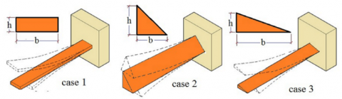
The cross-sectional shapes affect the static and dynamic responses of the beam as they change the moment of inertia and the eccentricities which lead beam to show torsional frequencies in addition to the transverse frequencies, and natural frequencies may shift due to eccentricities. The goal of this research is to predict the influence of eccentricity on the dynamic response when the center of gravity for different cross-sectional area shapes of a cantilever is shifted from the vertical and horizontal paths of vibration. This study is done by changing the ratio of the height to the base dimensions of the beam cross-sectional area. A deep understanding of modal properties is the base for effective design. The significance of this paper is to help in selecting the appropriate cross-sectional shape of cantilever in structure design according to the function of the structure, as the natural frequencies and mode shapes change with each cross-sectional shape. In this study, a finite element modal analysis was employed for three cases with various cross-sectional shapes and eccentricities as shown in Figure 1. It was used to investigate the complicated properties of various materials such as natural frequencies, and mode shapes. The first methodology was established on the Euler–Bernoulli beam principle, which is a mathematical model. Then, the finite-element procedure was implemented. The natural frequencies and mode shapes were predicted using ANSYS 16.1 program. Following these two analyses, an experimental modal analysis was done to match the results and interpret them for validity. To achieve natural frequencies and mode shapes, The 107 VF Vibration Analyzer is used to establish an experimental setup.
Modal analysis can be used to determine the structures' modal parameters. The modal parameters, which comprise natural frequencies and mode shapes, are the essential elements that characterize a structure's reaction to free vibration. An experimental modal analysis was done after these two analyses in order to compare the data and assess them for validity. The topics have been covered in few research papers and case studies. Lee and Lee [1] used an axially functionally graded material with rectangular and elliptical cross-sections. A uniform rectangular cross-section cantilever beam with finite lengths was the subject of Ali's research [2]. The dynamic response of the cantilever was examined in three different scenarios: rigid root, resilient root, and resilient root combined with a range of ambient temperatures.
The FEM model was used in FEM kit ABAQUS by Satpathy and Dash [3]. The results were investigated and compared experimentally. The theoretical and numerical modal analysis of cantilever beams was used by Du and Shi [4]. They used ANSYS 14.5 to generate the numerical data. The numerical and theoretical results were shown to be highly correlated. Bouamama et al. [5] explained the precise Euler Bernoulli theory solution for the free-vibration analysis of beams in material gradients subjected to various support circumstances. It is assumed that the exponential function governs the continuous change in material properties along the length of the beam. Fundamental frequencies are discovered by resolving the equations governing the eigenvalue issues, and the equations of motion are produced by using the principle of virtual works on beams. For various state boundaries, numerical results are presented to explain how the material affects the beam's fundamental frequencies.
Gautam et al. [6] investigated long, thin cantilever beams and developed a beam vibration equation. The Euler–Bernoulli beam principle is used. Ghaemdoust et al. [7] used the analytical and the finite element method to determine the fundamental natural frequency of unbonded pre-stressed beams. Adair and Jaeger [8] calculated non-uniform cantilever beams with a free transverse vibration caused by an axially and transversely eccentric tip mass. Here, the effects of the varying axial force are considered. To solve the equations for the transverse vibrations of a cantilever beam with an eccentric tip mass, Matt [9] used an integral transform method based on Eigen function expansion and an implicit filter pattern. The modal function and natural frequency of a beam with an arbitrarily variable section are obtained by Feng et al. [10] utilizing an all-encompassing analytical technique based on segmentation analysis and iteration computation. In order to investigate the coupled torsional free vibration of circular, horizontally curved beams. Using ABAQUS software, He [11] numerically studied the dynamic reaction of a single thin rectangular plate, and the results were compared experimentally. Abdulsahib and Atiyah [12] have examined the vibration of double beams using an elastic connecting layer. The beam has been considered to be a Bernoulli-Euler beam. At various boundary conditions, the symmetric double beam's natural frequencies equations have been calculated. Investigations on the behavior of certain frequencies have been conducted with changes in the connected layer's stiffness, the beam's elasticity modulus, its length, its mass density, and its thickness.
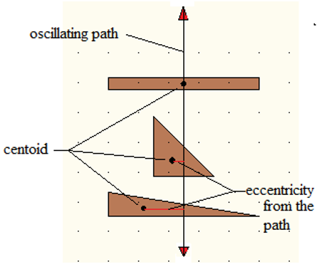
A cantilever beam's natural frequency can be established by applying the Euler-Bernoulli beam theory. Consider a structural steel (S. St.) beam Euler-Bernoulli case 1 in (Figure 1) undergoes transverse vibration. The dimensions and mechanical properties for all the cases are listed in Table 1. The eccentricity of the geometric center from the path of transverse vibration for the three cross-sectional area shapes are shown in Figure 2, and their values for each case have been calculated and specified in Table 2.
Figure 1. Cantilever beam with three different cross-sectional shape cases
Table 1. Mechanical properties and dimensions for the (S. St.) cantilever
|
Cross Section Types and Cases |
Dimensions [mm] |
Density ρ [kg/m3] |
Modulus of Elasticity E [N/m2] |
Polar Moment of Inertia J [mm4] |
Shear Modulus G [N/m2] |
Moment of Inertia Ip [mm4] |
||
|
b |
h |
L |
||||||
|
Rectangle Case 1 |
50 |
4 |
500 |
7850 |
200×109 |
41933 |
7.6923×10¹⁰ |
267 |
|
Triangle Case 2 |
20 |
20 |
500 |
7850 |
200×109 |
8889 |
7.6923×10¹⁰ |
4444 |
|
Triangle Case 3 |
50 |
8 |
500 |
7850 |
200×109 |
28489 |
7.6923×10¹⁰ |
711 |
Figure 2. Eccentricities between the oscillating path and the center of gravity of the cross-sectional area shapes of the cantilever
Table 2. Eccentricities of the geometric center from the path of transverse vibration for the three cross-sectional area shapes
|
Cross Section Type |
Eccentricity x |
Eccentricity y |
|
Rectangle Case 1 |
0 |
0 |
|
Triangle Case 2 |
3.34 |
3.34 |
|
Triangle Case 3 |
8.34 |
1.34 |
Using Euler-Bernoulli Beam equation:
$E I \frac{d^4 y}{d x^4}+\rho A \frac{d^2 y}{d t^2}=0$ (1)
where, E is modulus of elasticity, I is moment of inertia, ρ is density, and A is the cross-sectional area.
From Eq. (1)
$Y(x, t)=X(x) T(t)$. (2)
The equation becomes:
$\frac{E I}{\rho A} \frac{d^4 X}{d x^4} T(t)+X(x) \frac{d^2 T}{d t^2}=0$ (3)
$\mathrm{C}^2 \frac{d^4 y}{d x^4}+\frac{d^2 y}{d t^2}=0$ (4)
where,
$\mathrm{C}=\sqrt{\frac{E I}{\rho A}}$ (5)
$\beta^4=\frac{\omega^2}{C^2}=\frac{\rho A \omega_n^2}{E I}$ (6)
$\omega_n=\left(\beta L^2\right) \sqrt{\frac{E I}{\rho A L^4}}$. (7)
where, ωn is angular frequency in radian / second, and L is the length.
But fn = $f_n=\frac{\omega_n}{2 \pi}$.
fn is the natural frequency in hertz, and ωn is the natural angular frequency.
$f_n=\frac{(\beta L)^2}{2 \pi} \sqrt{\frac{E I}{\rho A L^4}} \mathrm{~Hz}$ (8)
where, $\beta \mathrm{L}=\mathrm{k}=\frac{\pi}{2} \frac{3 \pi}{2}, \frac{5 \pi}{2}, \frac{7 \pi}{2} \ldots$ =(1.875, 4.693, 7.854, 10.995, 14.142, 17.285, 20.428…. etc.) [13-15].
$\mathrm{I}=\frac{b h^3}{12}, A=b \times h$
To find the natural frequencies for the first six modes of a (S. St.) cantilever, use the following formula:
(1) 1st Natural Frequency using Eq. (8):
$f_n=\frac{(\beta L)^2}{2 \pi} \sqrt{\frac{E I}{\rho A L^4}}$
$f_1=\frac{1.875^2}{2 \pi} \sqrt{\frac{200 \times 10^9 \times 50 \times 4^3}{7850 \times 12 \times 4 \times 50 \times 10^{-6} \times 500^4}}$.
$f_1=12.767 \mathrm{~Hz}$
(2) 2nd Natural Frequency using the same equation:
$f_2=\frac{4.694^2}{2 \pi} \sqrt{\frac{200 \times 10^9 \times 50 \times 4^3}{4 \times 12 \times 7850 \times 50 \times 4 \times 10^{-6} \times 500^4}}$.
f2 =81.755 Hz.
Table 3 shows the first six natural frequencies obtained analytically.
Using the equation below, the torsional natural frequencies for the (S. St.) cantilever were also determined [16, 17].
$\omega_n=\frac{D_n}{L} \sqrt{\frac{G J}{\rho I}}$. (9)
where, G is Shear Modulus, and J is Polar moment of inertia, ρ is density, L is length, I is moment of inertia.
$D_1=\frac{\pi}{2}, D_2=\frac{3 \pi}{2}, D_3=\frac{5 \pi}{2}, D_4=\frac{7 \pi}{2}, D_5=\frac{9 \pi}{2}, D_6=\frac{11 \pi}{2}, \ldots$ etc. [18, 19].
(1) 1st Torsional Natural Frequency:
$f_l=\frac{\pi}{2 \times 0.5 \times 2 \pi} \sqrt{\frac{7.6923 \times 50 \times 10^{10} \times 4^3 \times 12}{3 \times 7850 \times 4 \times 50^3}}$.
f1 =250.41 Hz.
(2) 2nd Torsional Natural Frequency:
$f_2=\frac{3 \pi}{2 \times 0.5 \times 2 \pi} \sqrt{\frac{7.6923 \times 10^{10} \times 50 \times 12 \times 4^3}{3 \times 4 \times 7850 \times 50^3}}$.
f2 =751.21 Hz.
Table 4 shows the results of the same computations for various upper Torsional Natural Frequencies.
The horizontal natural frequencies were obtained by the same formula for vertical natural frequencies. The dimensions for the cantilever were just replaced in calculations, i.e. h became b and b became h. The same calculation was done for case 2 and case 3 to obtain the effect of eccentricity.
Table 3. Natural frequencies of the (S. St.) cantilever investigated analytically case 1 (no eccentricity)
|
Mode Shapes |
Natural Frequencies [Hz] |
|
1 |
12.767 |
|
2 |
81.755 |
|
3 |
228.94 |
|
4 |
448.641 |
|
5 |
742.186 |
|
6 |
1108.712 |
Table 4. Analytical torsional natural frequencies for (S. St.) cantilever case 1
|
Mode Shapes |
Torsional Natural Frequencies [Hz] |
|
1 |
250.4 |
|
2 |
751.2 |
|
3 |
1552 |
|
4 |
1752.8 |
|
5 |
2253.6 |
|
6 |
2754.4 |
A model was drawn in ANSYS 16.1 program. Case 1 was represented by a single cantilever beam model. The modal analysis technique involves the following steps:
1) Select the modal operation from the analysis system in the tool box.
2) Use the material properties tool.
3) Create a model of a cantilever beam.
4) For finite element calculations, use a suitable mesh. The element has a 0.5 mm edge length.
5) The boundary condition is established by restricting all degrees of freedom at one end while leaving the other free.
6) Calculate first six mode shapes.
7) Solve the model.
8) Examine the results.
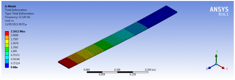
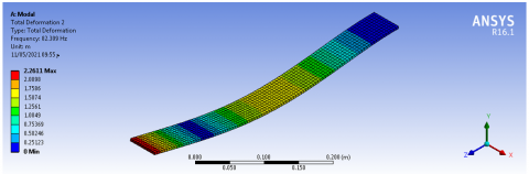
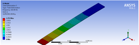
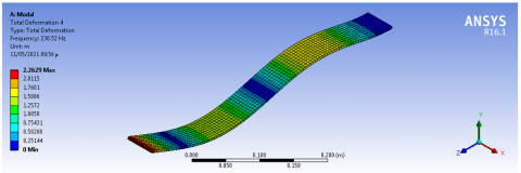
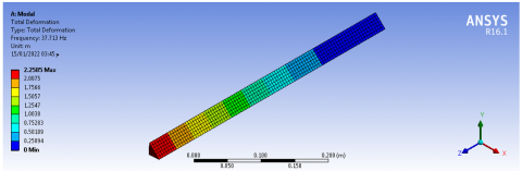
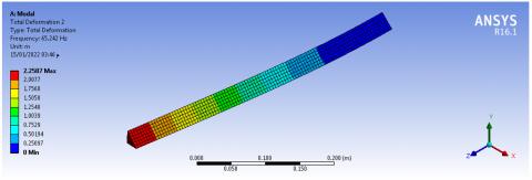
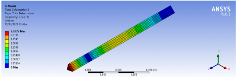
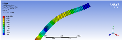
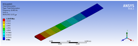
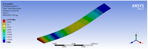
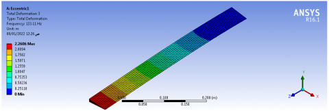
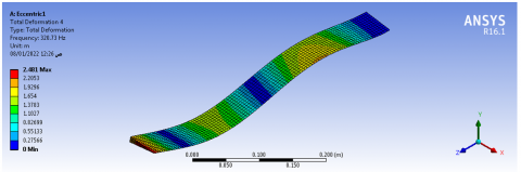
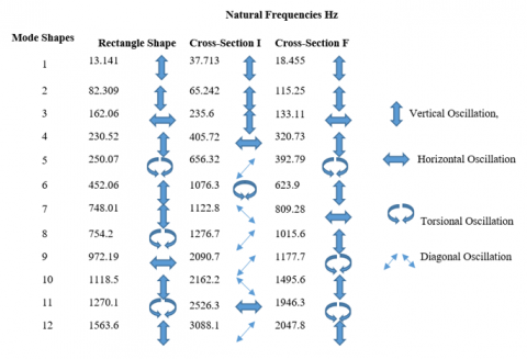
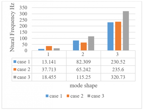
Figures 3-6 show the mode shapes and natural frequencies for case 1. The mode shape will be denoted in figures titles as (M.S) and the natural frequency as (N.F). All the steps that done for case 1 was repeated for case 2 and case 3, Figures 7-10 are for case 2, and Figures 11-14 are for case 3. Figure 15 shows the natural frequency values for each mode shape, for the three cases obtained numerically using ANSYS 16.1.
Figure 3. First M.S and N.F for (S. St.) cantilever case 1
Figure 4. Second M.S and N.F for (S. St.) cantilever case 1
Figure 5. Third M.S and N.F for (S. St.) cantilever case 1
Figure 6. Fourth M.S and N.F for (S. St.) cantilever case 1
Figure 7. First M.S and N.F for (S. St.) cantilever case 2
Figure 8. Second M.S and N.F for (S. St.) cantilever case 2
Figure 9. Third M.S and N.F for (S. St.) cantilever case 2
Figure 10. Fourth M.S and N.F for (S. St.) cantilever case 2
Figure 11. First M.S and N.F for (S. St.) cantilever case 3
Figure 12. Second M.S and N.F for (S. St.) cantilever case 3
Figure 13. Third M.S and N.F for (S. St.) cantilever case 3
Figure 14. Fourth M.S and N.F for (S. St.) cantilever case 3
Figure 15. Natural frequencies for the three cases obtained numerically using ANSYS 16.1
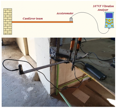
A structural steel beam with the specified dimensions (L=500 mm plus 100 mm for beam clamping, (a=4 mm, b=50 mm)) which represents case 1, was investigated to determine the natural frequencies. Figure 16 shows the experimental operation. The location of the accelerometer and the point of impact are specified in points that the natural frequencies could be found easily. The cantilever beam was set free at one end and fastened at the other end. An accelerometer was located at the free end with the help of a magnetic to measure the vibration, and the accelerometer’s signal was sent to the 107 VF Vibration Analyzer to convert it from time domain to frequency domain and assign the natural frequencies. A small knock at the free end to begin the free oscillation. The test was carried out a total of ten times. Tables 5 and 6 illustrate the data that was collected.
Figure 16. Experimental set up
Table 5. Experimental mode shape and natural frequencies for (S. St.) cantilever
|
Mode Shapes |
Natural Frequencies [Hz] |
|
1 |
15.12 |
|
2 |
89.53 |
|
3 |
153.2 |
|
4 |
211.6 |
|
5 |
225.1 |
|
6 |
489.2 |
|
7 |
723.5 |
|
8 |
745.9 |
|
9 |
910.2 |
|
10 |
1216.2 |
|
11 |
1475.3 |
|
12 |
1354.3 |
Table 6. Natural frequencies and mode shapes for three methods (analytical, numerical, and experimental) for the (S. St.) rectangular cross-sectional shape cantilever beam (case 1)
|
Mode Shapes |
Natural Frequency [Hz] |
Standard Deviation |
|||
|
ANSYS |
Analytical |
Experimental |
Mean Value |
||
|
1 |
13.141 |
12.767 |
15.12 |
13.676 |
1.264445 |
|
2 |
82.309 |
81.755 |
89.53 |
84.531 |
4.337826 |
|
3 H* |
162.06 |
166.34 |
153.2 |
160.533 |
6.701711 |
|
4 |
230.52 |
228.94 |
211.6 |
223.687 |
10.49713 |
|
5 T** |
250.07 |
250.4 |
225.1 |
241.857 |
14.51264 |
|
6 |
452.06 |
448.641 |
489.2 |
463.300 |
22.49482 |
|
7 |
748.01 |
742.186 |
723.5 |
737.898 |
12.80511 |
|
8 T |
754.2 |
751.2 |
745.9 |
750.334 |
4.202777 |
|
9 H |
972.19 |
1002.631 |
910.2 |
961.673 |
47.10432 |
|
10 |
1118.5 |
1108.712 |
1216.2 |
1147.804 |
59.43451 |
|
11 T |
1270.1 |
1552 |
1475.3 |
1432.467 |
145.7495 |
|
12 |
1563.6 |
1548.545 |
1354.3 |
1448.815 |
116.7364 |
* Horizontal natural frequency is denoted by the blue letter H.
** Torsional natural frequency is denoted by the red letter T.
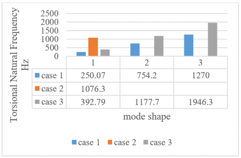
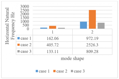
Three cases were investigated in this paper with different eccentricities between the center of gravities of the cross-section area shape of a cantilever beam and path of oscillation to find the effect of eccentricity on the dynamic response of a cantilever. Case 1 was a rectangular cross-sectional shape cantilever beam, case 2 was a triangular shape cross-sectional shape cantilever with a ratio of h/b=1, case 3 was a triangular cross-sectional shape with a ratio of h/b =8/50. These ratios were chosen to maintain the area of the cross section for the three cases equal to 200 mm2. This study used numerical modal analysis to find natural frequencies for each mode shape of a single cantilever beam with different cross sections. The natural frequencies of torsional (flexural) and horizontal vibrations were found and separated from the transverse vertical vibration. Table 4 demonstrates that the first two mode shapes for the three cases have vertical oscillation. The third mode shape was different among the three cases, while the third mode of case two with the ratio of h/b=1 is still vertical, the other cases have horizontal oscillation. The horizontal oscillation in case 1 was the fourth natural frequency. The torsional natural frequency appeared at the fifth mode shape for both case 1 and case 2, while it appeared as the sixth mode shape in case 2. The vertical natural frequencies were collected together in Figure 17, The first three mode shapes were selected, it can be shown that the fundamental natural frequency for the rectangular shape was the lower one, while the higher fundamental natural frequency was in case 2. The torsional natural frequencies were collected together in Figure 18. The first three mode shapes were selected, it can be shown that the first torsional natural frequency for the rectangular shape was the lower one. The second and third torsional natural frequencies for case 2 was not shown in the figure, because they did not appear within the first 12 mode shapes that been studied in this paper. It means that their values are higher than expected. The horizontal natural frequencies were collected in Figure 19. The first two horizontal natural frequencies that appeared within the first 12 mode shapes were selected. Case 3 has the lower horizontal natural frequency, while case 2 had the higher one. From all this, it appeared that case 2 with h/b=1 undergoes a diagonal path vibration, but it was the more stable from the other two cases.
Figure 17. Differences between first three set of vertical natural frequencies for the three cases
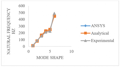
To verify these results, the mathematical method was used to determine the natural frequencies and mode shapes for case 1, the rectangular cross section cantilever. In addition to that, an experimental method was used to verify the two methods. The natural frequencies and mode shapes are shown in Figure 15. A comparison was done between the three methods for the rectangular cross section cantilever beam. Table 5 shows the natural frequencies and mode shapes for the three methods, the mean values, and the standard deviations. It can be shown from Figure 20 for natural frequencies of the Structural Steel rectangular cantilever that there is a good match for the first three natural frequencies, and other natural frequency values are still acceptable. The first natural frequencies have a standard deviation of 1.26, whereas the twelfth natural frequencies have a standard deviation of 116.73.
Figure 18. Differences between first three set of torsional natural frequencies for the three cases
Figure 19. Differences between first three set of horizontal natural frequencies for the three cases
Figure 20. First six natural frequencies and mode shapes of (S. St.) rectangular cantilever by three methods
The analytical, numerical, and experimental modal analysis of a cantilever beam has been completed in this research. The effect of the shape of the cross-sectional shape cantilever beam was studied in this paper. It can be shown that the shape of the cross section and the ratio of its height to the base affects the dynamic response for the cantilever beam due to the eccentricity. ANSYS and experiment were used to compare the Euler-Bernoulli analysis method and estimate the natural frequencies for a variety of mode shapes. The three approaches' outcomes were found to be closely connected. The results of numerical method and experimental test were found to be very similar. For long beams with no shear deformation features, the Euler-Bernoulli equation is proved to be effective. Even though the cantilever beam has no eccentricities between the center of gravity and centroid, torsional natural frequencies were visible inside the transverse natural frequency.
This work is done in the Northern Technical University in Iraq, at the Engineering Technical College, Mosul.
[1] Lee, J.K., Lee, B.K. (2022). Coupled flexural-torsional free vibration of an axially functionally graded circular curved beam. Mechanics of Composite Materials, 57(6): 833-846. https://doi.org/10.1007/s11029-022-10003-8
[2] Mohammed Sarhan, S., Al-Zubaidi, S. (2023). Mathematical modeling of the effect of temperature on the dynamic characteristics of a cantilever beam with flexible root. The Scientific World Journal, 2023: 6568120. https://doi.org/10.1155/2023/6568120
[3] Satpathy, S.M., Dash, P. (2014). Dynamic analysis of cantilever beam and its experimental validation. Doctoral Dissertation, Mechanical Engineering National Institute of Technology Rourkela.
[4] Du, Y., Shi, L. (2014). Effect of vibration fatigue on modal properties of single lap adhesive joints. International Journal of Adhesion and Adhesives, 53: 72-79. https://doi.org/10.1016/j.ijadhadh.2014.01.007
[5] Bouamama, M., Elmeiche, A., Elhennani, A., Kebir, T., Harchouche, Z.E.A. (2020). Exact solution for free vibration analysis of FGM beams. Revue des Composites et des Matériaux Avancés-Journal of Composite and Advanced Materials, 30(2): 55-60. https://doi.org/10.18280/rcma.300201
[6] Gautam, A., Sharma, J.K., Gupta, P. (2016). Modal analysis of beam through analytically and FEM. International Journal of Innovative Research in Science and Engineering, 2(5): 373-381.
[7] Ghaemdoust, M.R., Wang, F., Li, S., Yang, J. (2021). Numerical investigation on the transverse vibration of prestressed large-span beams with unbonded internal straight tendon. Materials, 14(9): 2273. https://doi.org/10.3390/ma14092273
[8] Adair, D., Jaeger, M. (2018). Simulation of the vibrations of a non-uniform beam loaded with both a transversely and axially eccentric tip mass. Computational and Experimental Studies, 57-68. https://doi.org/10.2495/CMEM-V6-N4-679-690
[9] Matt, C.F.T. (2013). Simulation of the transverse vibrations of a cantilever beam with an eccentric tip mass in the axial direction using integral transforms. Applied Mathematical Modelling, 37(22): 9338-9354. https://doi.org/10.1016/j.apm.2013.04.038
[10] Feng, J., Chen, Z., Hao, S., Zhang, K. (2020). An improved analytical method for vibration analysis of variable section beam. Mathematical Problems in Engineering, 2020: 1-11. https://doi.org/10.1155/2020/3658146
[11] He, X.C. (2012). Numerical and experimental investigations of the dynamic response of bonded beams with a single-lap joint. International Journal of Adhesion and Adhesives, 37: 79-85. https://doi.org/10.1016/j.ijadhadh.2012.01.008
[12] Abdulsahib, I.A., Atiyah, Q.A. (2022). Vibration analysis of a symmetric double-beam with an elastic middle layer at arbitrary boundary conditions. Mathematical Modelling of Engineering Problems, 9(4): 1136-1142. https://doi.org/10.18280/mmep.090433
[13] Jalali, H., Ahmadian, H., Mottershead, J.E. (2007). Identification of nonlinear bolted lap-joint parameters by force-state mapping. International Journal of Solids and Structures, 44(25-26): 8087-8105. https://doi.org/10.1016/j.ijsolstr.2007.06.003
[14] Patil, Y.B., Barjibhe, R.B. (2013). Modal analysis of adhesively bonded joints of different materials. International Journal of Modern Engineering Research, 3(2): 633-636.
[15] Ugural, A.C., Fenster, S.K. (2011). Advanced Mechanics of Materials and Applied Elasticity. Pearson Education.
[16] Zannon, M. (2014). Free vibration of thin film cantilever beam. International Journal of Engineering and Technical Research (IJETR), 2(11): 304-314.
[17] Green, C.P., Sader, J.E. (2002). Torsional frequency response of cantilever beams immersed in viscous fluids with applications to the atomic force microscope. Journal of Applied Physics, 92(10): 6262-6274. https://doi.org/10.1063/1.1512318
[18] Blevins, R.D. (1979). Formulas for Natural Frequency and Mode Shape. Van Nostrand Reinhold, New York.
[19] Beards, C.E. (1996). Structural Vibration. First published in Great Britain by Arnold.