Salam O. Dahi*![]() | Ahmed Ali A. Al-Shawk
| Ahmed Ali A. Al-Shawk![]() | Hussein Al-Gburi
| Hussein Al-Gburi![]()
© 2024 The authors. This article is published by IIETA and is licensed under the CC BY 4.0 license (http://creativecommons.org/licenses/by/4.0/).
OPEN ACCESS
Friction Stir Spot Welding (FSSW) has emerged as a promising alternative to traditional riveting in the automotive industry. In this study, we explore the application of double-sided FSSW, a solid-state joining method, as an innovative approach to overcome the limitations of conventional resistance spot welding. Our focus is on welding 2 mm thick sheets of aluminum alloy AA6061-T4. To improve the strength and quality of welded joints, we employed the double-sided FSSW technique, which utilizes a revolving anvil and a pin-less tool. This approach not only enhances the tensile strength of the connections but also mitigates potential defects such as keyholes. Intriguingly, our numerical analysis reveals the complexity of material flow between the rotating anvil and the pin-less tool during the welding process. This complexity underscores the suitability of using a rotating anvil and a pin-less tool in FSSW operations, particularly when welding larger sheets. In conclusion, our study underscores the potential of double-sided FSSW with a rotating anvil and pin-less tool for achieving robust weld connections in the context of aluminum alloy AA6061-T4. These findings contribute to the ongoing efforts to advance solid-state joining methods in the automotive industry, offering a more efficient and reliable alternative to traditional riveting.
spot welding, rotation anvil tool, pin less tool, micro hardness, Al-Alloy AA6061-T4
In recent years, the automotive industry has been seeking innovative alternatives to traditional riveting for joining components. Friction Stir Spot Welding (FSSW) has emerged as a promising candidate for addressing this need. However, to fully understand the significance of our study, it is crucial to delve into the underlying motivations and practical implications of investigating FSSW for automotive applications.
Current research seeks to answer the question: Why is the study of stir friction spot welding being conducted in the context of the automotive industry? This question is of paramount importance because it directs our focus towards the challenges and opportunities that FSSW presents. Traditional resistance spot welding has limitations when it comes to welding thin sheets of materials, particularly aluminum alloy AA6061-T4, which is widely used in the automotive sector due to its lightweight and corrosion-resistant properties.
As a solid-state joining method, friction stir welding was created in 1991 at the UK welding laboratory TWI [1]. It makes use of a non-consumable rotational tool with a pin and shoulder that are particularly made and put into the joint's connecting and traversal plates on the outside edges. As opposed to friction stir welding, Friction Stir Spot Welding is accomplished by pushing and pulling a rotating tool in a single location on an AA6061-T4 aluminium surface. The design of the tool has a significant impact on the Friction Stir Spot Welding process's characteristics [2].
Although instrument configuration plays an important role in achieving high strength spot welding, other pin-less plans are extremely limited, and the examination of device configuration is also limited. Much recent writing has detailed the investigation of cycle boundaries on weld properties, but advancement for weld properties is only done on occasion [3]. The FSSW (double side) technique has been used with a rotational anvil and a pin-less tool together. A rotational anvil, similar to the design of a pin-less tool, that can be used for welding thin sheets.
The keyhole, which may have weakened the weld, was removed using a pin-less tool. This method, however, can only be used to attach thin sheets that are under 1 mm thick [4]. Together with decreasing reaction forces on the spot-welding frame, combining the rotatable anvil with the FSSW method enables the joining of thicker cross sections and enhances the mechanical strength of the spot weld. Shear testing and micro section are also employed to assess weld joints.
The macro section explains that materials flow between the pin-less tool and the rotation anvil in a complex and unique process [5]. The use of a pin-less tool and rotational anvil technique with the FSSW process produces high-quality weld joints with thicker sheets [6]. The double-sided FSSW process achieves good material flow and gives good welding joint properties using different values of heat input through the rotation of the pin tool and rotary anvil, which reduces the dwell time and high thermal conductivity problem of aluminium alloys in addition to preventing the expansion heat effect zone [7].
Double side FSSW is one of the better high-thickness sheet welding methods; it employs a pin-less tool and a rotating anvil [8, 9]. It seems such research is inadequate and deserves further work [10]. A lot of current literature records the analysis of welding process parameters on welding properties; further research is needed to optimize welded properties [11]. Likewise, seeing how material moves during various phases of the FSSW cycle is fundamentally essential to achieving improved welding boundaries and acquiring elite execution welds [12]. Thus, much more study is required to comprehend the spot-welding process [13]. Interfacial shear fracture, nugget pull-out fracture, and upper or lower sheet fracture are the typical three failure modes in shear tests; nevertheless, the fatigue cracks commonly propagate through the hooked tip. A sufficient database and an insufficient theory still exist. Applications of the FSSW technique and knuckle precision are not completely understood [14]. The study conducted by Dourandish et al. [15] provided significant contributions in terms of understanding a new welding methodology and its practical implementation on 2024 aluminium alloy. The study demonstrated the enhanced mechanical qualities of protrusion Friction Stir Spot Welding in comparison to traditional approaches. Furthermore, it furnished crucial data regarding the impact of nugget zone features on the failure mode of the welds, hence enhancing our comprehension of the welding procedure. The practical feasibility of achieving high-quality welds in 2024 aluminium alloy components is emphasised by the successful determination of optimal welding parameters in protrusion Friction Stir Spot Welding. The study conducted by Zhang et al. [16] offered a thorough assessment of the Friction Stir Spot Welding (FSSW) approach in the context of joining sheets made of 5052-H112 aluminium alloy. The research provided valuable insights into the impact of rotating speed, dwell duration, and welding technique on the resulting microstructure and mechanical properties. The results of this study hold significant value for scholars and professionals engaged in the domain of solid-state welding, particularly those involved in similar materials and applications. The study done by Babu et al. [17] examined the application of Friction Stir Spot Welding (FSSW) in the manufacture of aluminium sheet metal. The aforementioned text underscored the potential advantages of the technology, substantiated its superiority in comparison to riveting, and offered significant insights for scholars and practitioners involved in the domain of welding and aluminium constructions. The study conducted by Bakavos and Prangnell [18] provided a significant contribution to the continuous advancement and refinement of Friction Stir Spot Welding techniques specifically for automotive closing panels manufactured from thin 6111-T4 aluminium. The results provided valuable insights into the impact of pin length and the utilisation of an insulating anvil on the welding procedure. Moreover, the use of a pinless tool has introduced a promising opportunity for further investigation in the field of Friction Stir Spot Welding (FSSW) technology. This study highlights the significance of customising welding parameters according to the characteristics of materials and intended applications in order to optimise joint quality and efficiency.
Based on a comprehensive examination of the existing literature, it is determined that a substantial body of research exists on Friction Stir Spot Welding, encompassing several configurations. However, certain research gaps persist, which will be addressed in the forthcoming study. Further investigations are required to comprehensively examine the impact of sheet thickness and process factors on the mechanical properties of aluminium AA6061-T4 when subjected to a rotating anvil. The latest research holds significant practical implications in terms of its potential to revolutionise the field of vehicle manufacture. Through an examination of the implementation of double-sided Friction Stir Spot Welding (FSSW), a technique for solid-state joining, our objective is to surmount the constraints associated with traditional resistance spot welding. This phenomenon has the potential to yield significant advantages, including as increased tensile strength in welded connections and a decrease in prevalent imperfections such as keyholes.
The friction process between the rotating tool and the work piece is the main heat source in FSW friction welding [3], according to Coulomb's law, where the force of local friction, Ff is calculated as Eq. (1) [7].
Considered friction between the rotation tool and work piece is a major heat source in FSW [3], according to Coulomb’s law, where topical friction force, Ff is calculated as:
$F_f=\mu F_n$ (1)
where, μ friction coefficient between tool shoulder surface and work piece, Fn normal force applied on work piece (axial forces). Friction heat at then can be formulated as:
$Q_F=F_f V$ (2)
where, QF frictional heat, V rotating velocity of tool [8].
The aluminum alloy rolled sheets AA6061-T4, by 2mm thickness, experimental chemical composition as shown in Table 1. These sheets be used in producing overlapping joints, for the necessary tests.
Table 1. Chemical synthesis of AA6061-T4 compound, wt.%
|
Al |
Si |
Cu |
Mg |
Mn |
Cr |
Fe |
|
Ball |
0.48 |
0.32 |
0.75 |
0.25 |
0.10 |
0.20 |
Table 2. The processing conditions
|
Specimen No. |
Rotation Speed (rpm) |
Shoulder Plunge Depths (mm) |
Dwell Time (s) |
|
1 |
2000 |
0.3 |
3 |
|
2 |
2000 |
0.5 |
5 |
|
3 |
2000 |
0.7 |
7 |
|
4 |
3000 |
0.3 |
3 |
|
5 |
3000 |
0.5 |
5 |
|
6 |
3000 |
0.7 |
7 |
2.1 The equipment
Welding process been performed for pre-determined samples, by used a double Side FSSW process, by welding parameters determined, on a welding machine with rotational speeds 1000 to 3000 rpm, axial load 12 kN and plunge rates 0.1 to 10 mm/s, with the ability to control the penetration depth ± 0.1 mm. Welding be performed under position control according to the processing conditions, plunge rate was 10mm/min, where shoulder plunge depth been selected following preliminary weld experiments, where use in producing good quality weld for joints [10-12].
2.2 The tools
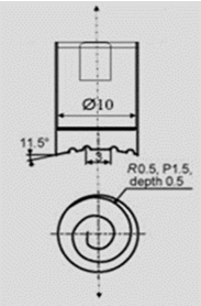
Pin less tool and rotating anvil, both of which have the same design and are unique tools for this experiment because they have a scroll groove of 0.5 mm in depth and a shoulder surface, are the tools employed in the current investigation as shown in Figure 1. High-speed steel tool with concave shoulder, 10mm in diameter, and 11.5° concavity angle.
Figure 1. Configuration of a tool
2.3 The specimens
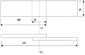
The specimens be produced on strips, according to overlap standard specimen geometry JIS- Z3136, where the strips were sheared to lap-shear specimens as shown in Figure 2, all the specimen in this study have 25mm square overlap area, which been used in required tests of the weld joint.
Figure 2. Schematic drawing of the weld joint: (a) Front view; (b) Top view
In FSSW process, the significant handling factors are the instrument rotational speed and the apparatus abide time; notwithstanding these factors the shoulder plunge profundity is accepted to be another variable especially for both the parchment device and the pivoting iron block. As displayed in Table 2, the device rotational paces of 2000 and 3000 rpm, stay times 3, 5 and 7 s and plunge profundities 0.3, 0.5, 0.7 mm, are utilized. In all cases, the dive rate 10 mm/min, is utilized. The lap-shear example's surface is cleaned and is ready before the joining system. These boundaries decide the properties of weld joints by their impact on the measure of hotness created during rubbing, the stream pace of the material under the apparatus, and the plan of the weldments [19, 20].
3.1 Micro hardness
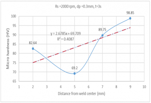
In this investigation an attempt was made to understand the effect of Friction Stir Spot Welding of aluminum alloy AA6061-T4 on Micro hardness of welded joints. A number of experiments were carried out to achieve the optimum Micro hardness values by changing the rotational speed in the range 2000-3000 rpm and 10 mm / min dip rate as shown in Table 3. Figure 3 displays weld joint's hardness distributions at different parameters. The softened zone consisting of HAZ, TMAZ and SZ exists in all joints, which is a typical characteristic of heat-treatable aluminum alloy FSSW joints. In softened area, hardness first decreased from the BMZ to HAZ, reaching the minimum value in the TMAZ, then increased in the SZ, but still below the BMZ value. All in all, the minimum alloy hardness value decreased with increased welding heat input, as shown in Table 3 with regard to aluminum alloy AA6061-T4, reinforcement of precipitation is the key reinforcement mechanism by which precipitates in HAZ will weaken their strength.
Figure 3. Experimental distribution of the weld joints by micro hardness
Therefore, hardness caused is lower than BMZ, second-phase particles dissolved in TMAZ almost; removes the reinforcing effect of precipitation, which is why the minimum hardness value is located in such zone. During FSSW process; in SZ, dynamic recrystallization occurred, in addition to dissolving second-phase particles, a fine grain increase material strength; which may re-precipitate with higher heat input during the zone cooling stage. As result, the hardness increased in the stir region, but stilled below that in the base metal region, where the upper and lower sheet materials were stirred and metallurgical bonded in the stir zone, while the average hardness value in stir zone is crucial to the spot weld joint's mechanical properties.
Table 3. Experimental micro-hardness values for weld zones with different processing parameter values
|
Specimen No. |
SZ |
TMAZ |
HAZ |
BMAZ |
Rs RPM |
Dp MM |
Dt S |
|
1 |
82.64 |
69.75 |
89.75 |
98.85 |
2000 |
0.3 |
3 |
|
2 |
83.64 |
69.12 |
88.87 |
98.75 |
2000 |
0.5 |
5 |
|
3 |
84.32 |
68.76 |
98.12 |
98.23 |
3000 |
0.3 |
3 |
|
4 |
85.32 |
69.21 |
86.78 |
98.25 |
3000 |
0.5 |
5 |
Figure 3 shows that the increase in the micro-hardness ratio of the SZ in the first series (test point distance from weld center: 2 mm) was 3.14 percent due to the amount of heat input, leading to dynamic re-crystallization and improved material strength of fine grains, in addition to the breakup of the second-phase particles, which may re-precipitate during the cooling stage of the zone having a higher heat supply. Increasing the ratio of TMAZ micro-hardness in the second series (test point distance from the weld centre is 5 mm); 0.65 percent; location of TMAZ near the stir zone; resulting in deformation and thermal effects the intense stirring effect can be useful for the homogeneity of the distribution of particles. However, the TMAZ zone in the joints produced by welding parameters showed a non-uniform distribution of second-phase particulate quantity from heat input in this zone, which almost dissolved second-phase particles and removed the force effect of the deposition. However, the micro-hardness ratio of the HAZ decreased in the third series (test point distance from weld centre 7 mm was 15.39% where the amount of heat input leads to rough particles; which weakens their strength and thus has less hardness than the BMZ zone). As for the decrease in BMZ micro-hardness within the fourth series (test point distance from weld center: 9 mm), it was 0.4 percent, which varies slightly because a limited extent is affected by heat input where raw particles have formed. It appears that the increase ratio of micro-hardness for the weld zones in all different series, as shown in Figure 3, varies due to the amount of heat input induced by changes in grain sizes, as shown in Table 4.
3.2 The results accuracy
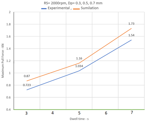
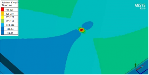
The simulation process of the experimental results was carried out using the programme (ANSYS) to check the accuracy of the experimental results (increasing the resistance of the welding joint against pull forces), where there was a good agreement between the experimental and simulation results according to the welding process parameters, as shown in Figure 4.
Table 4. Experimental values ratio micro-hardness for all series
|
Series No. |
Ratio % |
Distance MM |
Zone |
|
1 |
3.14 |
2 |
SZ |
|
2 |
0.65 |
5 |
TMAZ |
|
3 |
15.39 |
7 |
HAZ |
|
4 |
0.40 |
9 |
BMZ |
Figure 4. Experimental and simulation of pull force
According to Eq. (3), increasing in ratios of the resistance occur, as value of heat input increases; which induces changes in the grains size and strengthening precipitation.
Increasing ratio=$\frac{\text { Max.pull force }- \text { Min. pull force }}{\text { Max. pull force }}$ (3)
where, the percentage agreement between experimental and simulation results exceeded 93%, as shown in Table 5 and Figure 5, the simulation accuracy of the welding process is high.
Figure 5. Simulation of maximum pull force
Table 5. Experimental percentage of increase of resistance to pulling forces, also agreement between experimental and simulation results
|
Rotation Speed (rpm) |
Rotation Speed (rpm) |
Rotation Speed (rpm) |
Rotation Speed (rpm) |
|
2000 |
2000 |
2000 |
2000 |
|
3000 |
3000 |
3000 |
3000 |
In the FSSW process, a group of shear models were observed in the roll tests. Generally, FSSW fracture behavior can be categorized into two main modes:
Mode. I: The shear fracture passes through the joint line between two sheets in the weld plane, which occurs at a rotational speed of 2000 rpm, where the maximum shear strength value at 7 s of dwell time is 1.73 KN compared to less than 0.87 KN at 3 s of dwell time.
Mode. II: Where the interface flops, the upper sheet breaks around the edge arm, leaving the welding piece adhered to the base sheet. This break mode is caused by decreasing the upper sheet thickness at the device's shoulder edge due to the device's shoulder plunge profundity; cracks occurred at revolution rates of 3000 rpm, with the highest shear strength of 2.27 KN at the end of the 5s season, compared to the lowest worth of 2.024 KN at the end of the 3s season. When the welds were performed with various boundaries for each condition, significant changes in shear strength values could be noted when thinking about the stay time. Shear strength advantages of welds created with a rotational speed of 3000 rpm are in every case better than shear strength advantages of welds created with a pivot speed of 2000 rpm by the same various boundaries, aside from fascinating cases, where the shear strength esteem decreased at turning speed 3000 rpm for shoulder plunge profundities of 5mm, this implies a converse relationship between shoulder strength and shoulder profundity since sheet thickness under t. Figure 4 shows modes for miniature hardness profiles estimated for under shoulder plunge profundity and the upper surface lower part of welds made with the pin-less rotational iron block device.
The hardness side view of pin-less welds offers a "W" shape, which is commonly used in rubbing mix crease welds in comparable hotness treatable amalgams.
There is a drop-in hardness of 19% at the weld distance across, bringing about quick maturing, which ordinarily happens in the temperature range of 300-400℃. The minimal hardness situation nearly matches the TMAZ edge immediately under the machine shoulder. HAZ broadens sideways, and the base hardness was thicker at the TMAZ/HAZ limit when revolution iron block was utilized. The increase in HAZ width is more noticeable at the least point of welding, where the rotational blacksmith's iron is expected to have more effect, and the rotational iron block also causes a higher level of normal post-welding maturing close to the weld edge, consistent with the higher temperature on the back essence of welds produced. Obviously, a lower thickness of coarse aggregate is generally near the cooler, welded edge, where the solvent second stages are for the most part broken down.
The effect of using a pin-less tool (scrolling tool) and a rotational anvil on the shear strength and micro hardness of welded joints produced from thin sheets (2 mm) of aluminum alloy AA6061-T4 depends on the welding conditions (welding process parameters, e.g., dwelling time, shoulder plunge depth, rotation speed).
(1). A noteworthy remark can be made regarding the positive correlation between dwell time and the enhancements observed in both weld strength and microhardness. This highlights the need of optimizing dwell time throughout the welding process in order to attain the desired attributes of the joint.
(2). The findings of the study indicate that the attainment of optimal shear strength is contingent upon the occurrence of plug fracture, specifically nugget pull out, rather than shear fracture, known as interface cleavage, during the event of failure. This observation offers a crucial comprehension of the mechanisms that drive the occurrence of joint failure and presents possibilities for improving the structural integrity.
(3). One significant practical implication of this finding is that maximizing shear strength can be achieved by prioritizing nugget pull (plug fracture) as the primary mode of failure, rather than interface cleavage. This understanding enables intentional engineering and regulation of welded junctions in order to get enhanced performance.
(4). The implementation of a rotating anvil has been discovered to enhance the shear strength of welds. Moreover, the research highlights the importance of utilizing a reduced number of pins that do not penetrate the bottom of the upper sheet in order to achieve optimal performance in weld joint. This discovery presents a counterargument to the prevailing belief that advocates for increased pin penetration, hence emphasizing a more effective methodology.
This conclusion is crucial for the actual application of the FSSW process, and contrary to popular belief, it is commonly considered that the tool must penetrate at least 25 percent of the lower sheet surface.
Although this work has yielded significant insights into the impact of welding circumstances and tool design on joint qualities, it is crucial to recognize the inherent limitations associated with this research.
The primary emphasis of the study was directed towards investigating the properties of aluminum alloy AA6061-T4 and thin sheets with a thickness of 2 mm. However, it should be noted that the findings and conclusions derived from this study may not be readily applicable to other materials and thicknesses due to the specific focus on the aforementioned alloy and thickness.
The investigation failed to take into account the wider environmental and economic ramifications associated with the welding process, thereby leaving room for potential future research on this topic.
The conclusions of the study are derived from empirical data, and additional analysis using computational modelling and simulation could offer more profound understanding of the fundamental mechanisms involved.
The potential for future study in this field encompasses:
Investigating the generalizability of these findings across a broader spectrum of materials and varying sheet thicknesses. This study aims to examine the extended-term durability and fatigue characteristics of welded joints subjected to diverse stress situations.
The economic viability of employing the suggested welding processes in industrial environments can be evaluated through the utilization of cost-benefit analyses.
In conclusion, the results of this study carry substantial implications for enhancing the efficacy and effectiveness of the Friction Stir Spot Welding (FSSW) procedure. Nevertheless, additional research is required to broaden the breadth and enhance our comprehension of this crucial welding technology.
[1] Salari, E., Jahazi, M., Khodabandeh, A., Ghasemi-Nanesa, H. (2014). Influence of tool geometry and rotational speed on mechanical properties and defect formation in friction stir lap welded 5456 aluminum alloy sheets. Materials & Design, 58: 381-389. https://doi.org/10.1016/j.matdes.2014.02.005
[2] Paidar, M., Khodabandeh, A., Sarab, M.L., Taheri, M. (2015). Effect of welding parameters (plunge depths of shoulder, pin geometry, and tool rotational speed) on the failure mode and stir zone characteristics of friction stir spot welded aluminum 2024-T3 sheets. Journal of Mechanical Science and Technology, 29: 4639-4644. https://doi.org/10.1007/s12206-015-1009-x
[3] Campanelli, L.C., Suhuddin, U.F.H., Santos, J.F.D., Alcântara, N.G.D. (2012). Parameters optimization for friction spot welding of AZ31 magnesium alloy by Taguchi method. Soldagem & Inspeção, 17: 26-31. https://doi.org/10.1590/S0104-92242012000100005
[4] Yang, Q., Mironov, S., Sato, Y.S., Okamoto, K. (2010). Material flow during Friction Stir Spot Welding. Materials Science and Engineering: A, 527(16-17): 4389-4398. https://doi.org/10.1016/j.msea.2010.03.082
[5] Su, P., Gerlich, A., North, T.H., Bendzsak, G.J. (2006). Energy generation and stir zone dimensions in friction stir spot welds. SAE Transactions, 717-725. https://www.jstor.org/stable/44722388
[6] Su, P., Gerlich, A., North, T.H., Bendzsak, G.J. (2006). Energy utilisation and generation during Friction Stir Spot Welding. Science and Technology of Welding and Joining, 11(2): 163-169. https://doi.org/10.1179/174329306X84373
[7] Ojo, O.O., Taban, E., Kaluc, E. (2015). Friction Stir Spot Welding of aluminum alloys: A recent review. Materials Testing, 57(7-8): 609-627. https://doi.org/10.3139/120.110752
[8] Sundaram, M., Visvalingam, B. (2016). Optimizing the Friction Stir Spot Welding parameters to attain maximum strength in Al/Mg dissimilar joints. Journal of Welding and Joining, 34(3): 23-30. https://doi.org/10.5781/JWJ.2016.34.3.23
[9] Rao, H.M. (2014). A fundamental study on the structural integrity of magnesium alloys joined by friction stir welding. The University of Alabama.
[10] Sundaram, M., Visvalingam, B. (2016). Optimizing the Friction Stir Spot Welding parameters to attain maximum strength in Al/Mg dissimilar joints. Journal of Welding and Joining, 34(3): 23-30. https://doi.org/10.5781/JWJ.2016.34.3.23
[11] Cox, C.D., Gibson, B.T., Delapp, D.R., Strauss, A.M., Cook, G.E. (2014). A method for double-sided Friction Stir Spot Welding. Journal of Manufacturing Processes, 16(2): 241-247. https://doi.org/10.1016/j.jmapro.2013.10.006
[12] Zhang, Z., Yang, X., Zhang, J., Zhou, G., Xu, X., Zou, B. (2011). Effect of welding parameters on microstructure and mechanical properties of friction stir spot welded 5052 aluminum alloy. Materials & Design, 32(8-9): 4461-4470. https://doi.org/10.1016/j.matdes.2011.03.058
[13] Hattingh, D.G., Von Wielligh, L., Thomas, W., James, M.N. (2015). Friction processing as an alternative joining technology for the nuclear industry. Journal of the Southern African Institute of Mining and Metallurgy, 115(10): 903-912. http://dx.doi.org/10.17159/2411-9717/2015/v115n10a2
[14] Chalmers, R.E. (2001). The friction welding advantage. Manufacturing Engineering, 126(5): 64-64.
[15] Dourandish, S., Mousavizade, S.M., Ezatpour, H.R., Ebrahimi, G.R. (2018). Microstructure, mechanical properties and failure behaviour of protrusion friction stir spot welded 2024 aluminium alloy sheets. Science and Technology of Welding and Joining, 23(4): 295-307. https://doi.org/10.1080/13621718.2017.1386759
[16] Zhang, Z., Yang, X., Zhang, J., Zhou, G., Xu, X., Zou, B. (2011). Effect of welding parameters on microstructure and mechanical properties of friction stir spot welded 5052 aluminum alloy. Materials & Design, 32(8-9): 4461-4470. https://doi.org/10.1016/j.matdes.2011.03.058
[17] Babu, S., Sankar, V.S., Janaki Ram, G.D., Venkitakrishnan, P.V., Madhusudhan Reddy, G., Prasad Rao, K. (2013). Microstructures and mechanical properties of friction stir spot welded aluminum alloy AA2014. Journal of Materials Engineering and Performance, 22: 71-84. https://doi.org/10.1007/s11665-012-0218-z
[18] Bakavos, D., Prangnell, P.B. (2009). Effect of reduced or zero pin length and anvil insulation on Friction Stir Spot Welding thin gauge 6111 automotive sheet. Science and Technology of Welding and Joining, 14(5): 443-456. https://doi.org/10.1179/136217109X427494
[19] Hamzah, A.H., Beidokhti, B., Sabea, A. Effect of double sided Friction Stir Spot Welding on mechanical properties for aluminum alloy AA6061-T6 by using a rotating anvil.
[20] Yang, Q., Mironov, S., Sato, Y.S., Okamoto, K. (2010). Material flow during Friction Stir Spot Welding. Materials Science and Engineering: A, 527(16-17): 4389-4398. https://doi.org/10.1016/j.msea.2010.03.082