Hazim Jassim Jaber*![]() | Sanaa T. Mousa Al-Musawi
| Sanaa T. Mousa Al-Musawi![]() | Atheer Raheem Abdullah
| Atheer Raheem Abdullah![]() | Sadoon K. Ayed
| Sadoon K. Ayed![]() | Hasan Shakir Majdi
| Hasan Shakir Majdi![]() | Nabeh Alderoubi
| Nabeh Alderoubi![]()
© 2024 The authors. This article is published by IIETA and is licensed under the CC BY 4.0 license (http://creativecommons.org/licenses/by/4.0/).
OPEN ACCESS
In order to mitigate the global energy problem and address environmental issues, it is becoming more important to include renewable energy sources, such as photovoltaic (PV) panels. However, the working temperature of PV panels has a major influence on their efficiency, which may result in a decrease in energy conversion efficiency and hasten deterioration. Phase change materials (PCMs) and heatsinks have been the focus of current research to improve the thermal performance of PV panels. Using PCMs and heatsinks, this work gives a thorough numerical and analytical examination targeted at improving the thermal efficiency of PV panels. The proposed study uses a multiphysics method to examine the performance of different PCM-based cooling systems in combination with conventional heatsinks by integrating heat transfer, fluid dynamics, and phase change phenomena. In order to do the numerical simulations, a complex mathematical model must be created and include important factors such as the surrounding temperature, solar radiation, panel material qualities, and PCM characteristics. The study investigates the transient behavior of the PCM during the charging and discharging processes, maximizing its heat storage and release capabilities. This is done by using verified computational techniques. The result of changing the thickness of the fin helps to understand the process of transferring thermal energy from the solar panel and passing it to the phase change material. The thickness of 1 mm was the surface temperature of 46.95 degrees Celsius, while the thickness of 2 mm was the temperature of the surface of the plate at 45.734 degrees Celsius. At a thickness of 3 mm, temperatures went down to 44.665 degrees Celsius. The benefit of reducing the temperatures on the surface of a solar panel is to obtain high efficiency and generate the largest possible capacity. A power voltage diagram with varying fin thickness shows that the value of the capacity increases with the increase in the thickness. The basic principle for comparison and understanding of the case is to increase the electrical efficiency, which is the basis for understanding the improvement in temperature.
photovoltaic panels, phase change material, heat sink, Simulink, CFD, thermal efficiency
Utilizing renewable energy sources has emerged as a key strategy for solving the urgent issues brought on by climate change and the limited availability of traditional energy sources. Photovoltaic (PV) panels offer the most potential among renewable energy technologies for capturing solar energy and transforming it into electricity. However, the working temperature of PV panels has a significant impact on their efficiency since high temperatures may impair energy conversion efficiency and hasten material deterioration. Researchers and engineers have investigated novel strategies to increase the thermal efficiency of PV panels in order to solve this pressing problem. Phase-change materials (PCMs) and heatsink incorporation into the PV panel system are viable routes. When a material undergoes a phase shift, such as from solid to liquid or vice versa, PCMs have the ability to absorb and release a significant quantity of latent heat. Excess heat produced by solar exposure may be efficiently absorbed and dissipated as necessary by carefully placing PCMs inside the PV panel assembly. This keeps the panel within an acceptable working temperature range. The concentrator photovoltaic (CPV) is cooled by an extraordinary intensity sink that utilizes stage change material (PCM) and metal froth (permeable) at a sun fixation proportion (CR) of 20. The metal froth with high warm conductivity implanted in PCM with high idle intensity might further develop the cooling effect of CPV. The electric proficiency of the sunlight-based cell ascends as the porosity diminishes, yet when the porosity drops, the amount of time expected to keep the CPV at a steady temperature becomes more limited. The level of the PCM-permeable cavity additionally influences the cooling influence and electrical effectiveness, with expanding the level (H) from 0.5x to 1.0x supporting electric proficiency and power efficiency by around half. At the point when the porosity is under 100%, the electric effectiveness would altogether drop [1]. A clever plan of incorporated concentrated photovoltaic (BICPV) frameworks has been matched with an original plan of stage change material (PCM) heat sinks. A mathematical model was checked and reproduced, and the liquefying and hardening of PCM were explored. The single-pack plan controlled the silicon temperature of CPV below 78℃, while the multi-pack course of action showed a stage change to fluid PCM at a pace of 97%. A nanofluid stream could set up to 97 and 90% of the initially liquefied PCM after an hour, individually [2]. This study presents exploratory outcomes on unsupported silicon photovoltaic boards (PV) that are latently cooled in different cooling designs and considers the utilization of stage change materials (PCM). During numerous long stretches of field checking, the 20Wp PV boards were assessed in settings typical of the Mediterranean district. A reference PV board was utilized to look at the trial discoveries of the two PV-PCM cooling frameworks. Results showed that the presentation of the PV framework (by and large power yield) was upgraded during the normal estimation time by around 2.5 percent on account of the thought of a total PCM compartment, while execution was further developed by 10.7% percent utilizing the special PV-PM inactive cooling procedure. How much PCM materials and aluminum were utilized in different holder designs was 47% and 36% less, separately, showing the potential for execution upgrades and asset usage, which would affect both monetary and ecological variables [3]. Stage change material (PCM)-based cooling arrangements have become progressively well-known due to diminished PV module temperature (TPV) and further developed execution. Notwithstanding, PCM Tmelt's misfortune is bigger than different misfortunes, and examining a solitary PCM is impossible for the entire year. This exploration analyzes how TPV differs in light of radically changed climatic circumstances. Pearson's connection approach is utilized to look at the connection between TPV and the encompassing temperature (Tamb) for summer and winter. Flowed PCM is picked for Thailand, with the principal layer having a lower Tmelt in the 36-39℃ range and the subsequent layer having a more noteworthy Tmelt. The examination accentuates the need to utilize different PCM-put-together frameworks depending on the locale and environment [4]. This study reviews the cooling of solar photovoltaic (PV) cells to increase cell life and electrical efficiency. It examines the implications of earlier studies and technical specifics for improvement. The study of a few studies on passive and active cooling methods reveals a correlation between the water-cooling method's flow rate and the cells' ability to function more efficiently and at lower temperatures. One of the most effective methods is to cool PV cells using phase change material (PCM). Supporting PV cell cooling in both hot and cold environmental circumstances is beneficial, but a suitable PCM for PV cell cooling applications is needed [5]. This paper reviews research efforts over the last five years on cooling strategies using phase-change materials (PCMs), nanofluids, and their combined usage. It has been shown that the highest PV-efficiency improvement of up to 20 percent may be achieved using a passive cooling technique with PCMs. Fins added to the PCM container at the PV's back increase the PCM's ability to transmit heat, and composite PCMs have recently attracted the attention of researchers interested in PV cooling. Additionally, combining passive and active cooling methods may further reduce PV-cell temperature, improve PV efficiency, and generate more thermal energy. Nanofluid-based PV/T systems may increase PV efficiency by more than 60%, and electrical power and efficiency may be further improved by combining nanofluid and nano-PCM. Finally, the economic feasibility and environmental effects of the aforementioned cooling systems were examined [6]. A study was conducted to improve passive cooling for a photovoltaic (PV) module in a finned heat sink container. Palm wax was selected as the phase-change material (PCM). Initial design and investigation of three various PCM containers, including finned, tubed, and grooved containers, were done. The finned container was discovered to have the optimum cooling performance, reducing the PV module temperature by 6.1 degrees Celsius. The module with no cooling was then compared to the passive cooling with the finned container after additional analysis. The findings showed that the PV performance with cooling significantly improved when the solar irradiation was greater than 500 W/m2, but if there is typically less irradiation, PV cooling is not necessary [7]. This exploration presents an original detached cooling solution for sun-oriented modules that uses regular watercourses for cooling. An oil made up of 82 weight percent coconut oil and 18 weight percent sunflower oil was combined with Boehmite nanopowder to work on the effectiveness of intensity transmission between PCM and cooling water. The outcomes exhibit the suitability of the recommended strategy for cooling the PV module without a siphoning framework. The expansion of nano-created oil gave expansions in the greatest delivered force of 44.74, 46.63, and 48.23 percent at radiation powers of 410, 530, and 690 W/m2 [8]. This study zeroed in on a trial exploration of utilizing another stage change material (PCM) to further develop the cooling execution of a PV module. Copper microchannel tubes with cold water going through them are used in a chamber at the back of the PV module to postpone the liquefying of the PCM material. Sheep fat was utilized as another PCM in the principal phases of the tests, and afterward CuO nanoparticles (0.004 (w/v)) were added to the sheep fat to work on its capacity to cool. Results showed that both PCMs (paraffin wax and sheep fat) may further develop cooling execution; however, sheep fat is more compelling than paraffin wax. The most extreme delivered power is improved by 24.6 to 26.2 percent compared with the design with no cooling framework and by 5.3 to 12 percent compared with paraffin wax [9]. This study evaluated the thermal and electrical performance of a photovoltaic solar panel cooled using a nano-suspension of multi-walled carbon nanotubes in water and ethylene glycol (50:50) (MWCNT/WEG50). An ultrasonic homogenizer and nonylphenol ethoxylates were used to stabilize the nanofluid at a pH of 8.9. A cooling jacket was created and affixed to the solar panel to decrease heat loss and increase the rate of heat transfer between the coolant and the panel. At various local periods and with varied MWCNT mass fractions, the system's electrical and thermal power as well as equivalent electrical-thermal power were evaluated. Results indicated that an increase in coolant mass concentration increased power output and electricity generation, while an increase in nanofluid mass concentration increased pumping power and decreased thermal-electrical equivalent power [10]. This study examined the effectiveness of a PV module cooling effect by using water and/or an Al2O3/PCM mixture with varying nanoparticle mass concentrations and mass fluxes. The findings showed that the compound strategy (Al2O3 nanoparticles + water) outperforms cooling with 100% water when added at a concentration of 1.31 kg/s. The compound approach also delivers the maximum PV performance when compared to all tested cooling technique parameters. In order to forecast the electrical, thermal, and total energy efficiency of the PV cell, experimental correlations are given [11]. The objective of this study is to explore the way that stage change materials (PCM) and Al2O3 nanoparticles may work on the warm administration and productivity of a coordinated PV-building framework. The review's technique includes assessing at the same time three distinct PV modules that are incorporated into building walls: unadulterated PCM and a blend of PCM. The discoveries exhibit that adding Al2O3 nanoparticles to the PCM further increases the chance of temperature guidance and the warm productivity of the incorporated modules. Furthermore, coordinating the PV with unadulterated PCM and improved PCM by nanoparticles can bring down the temperature of the modules by 8.1 and 10.6℃ and increase its effectiveness [12]. A photovoltaic-stage-change material (PV-PCM) framework is utilized in the UAE to save energy all year. A paraffin-based PCM with a liquefying scope of 38-43℃ is consolidated at the back of the PV board and measured by a form heat move model. Every period of the year, the liquefying and hardening portions are anticipated utilizing the model, and most of the year's not entirely settled to be steady. In hot climatic conditions, the PV-PCM framework expanded the PV's yearly electrical energy creation by 5.9% [13]. This study examines the literature on photovoltaic cooling methods that use phase change materials (PCM). It aims to pinpoint crucial research areas to guarantee dependable performance and the technology's commercial feasibility. With PV-PCM integrated systems, electrical efficiency increases of up to 5% have been seen. However, PCM's low thermal conductivity and significant undercooling are its two main drawbacks. According to a market analysis, PCM-based PV cooling technology hasn't yet been commercialized due to technical difficulties, expensive system prices, and a lack of stable working designs. Further research is needed to evaluate performance, identify economic benefits, extend PV panel lifespan, and perform LCA analysis. [14]. This article depicts how to utilize a stage change material to support the electrical proficiency and power results of photovoltaic (PV) boards. The stage change material RT28HC was utilized to alter the Canadian sun-oriented CS6P-M PV board. Real cell temperature data from PV boards with and without PCM was given and looked at. TRNSYS programming determined the most extreme and normal increase in electrical proficiency for PV-PCM boards, with Ljubljana's board delivering more control throughout the span of a year by 7.3 percent [15]. A review group from the Metal Development Affiliation (MCA) and a gathering of building protection organizations, photovoltaic (PV) producers, and energy research foundations analyzed an exploratory sunlight-based rooftop in East Tennessee, USA, somewhere in the range of 2009 and 2010. The significant objective was to thermally survey a clever material framework that consolidated metal rooftop boards with undefined silicon PV overlays. The exploratory rooftop/upper room gathering incorporated a stage change material (PCM) heat sink, a vented air pit over the rooftop deck, and warm protection with a coordinated reflecting surface to diminish warm connecting and lower rooftop-produced warm loads. The test discoveries uncovered that the trial rooftop game plan might diminish warming and cooling loads by generally 30% and half, respectively [16]. This study's main goal is to research and evaluate the possibility of increasing photovoltaic (PV) panels' thermal efficiency via the use of phase change materials (PCMs) and heatsinks.
The point of originality of this research paper lies in linking the simulation programs for the different physical sciences and their development to obtain results that keep pace with development in terms of showing the reality of the improvements that have been made. where the thermal results were obtained from the simulation program and linked to the electrical simulation with the Simulink program to show the electrical efficiency. Thus, the study lies in its comprehensive and innovative approach to increasing photovoltaic panel thermal efficiency through the integration of phase change materials (PCMs) and heatsinks. While the concept of using PCMs to enhance thermal performance in various applications is not entirely new, the specific focus on photovoltaic panels and the combined numerical and analytical study set this research apart from existing literature.
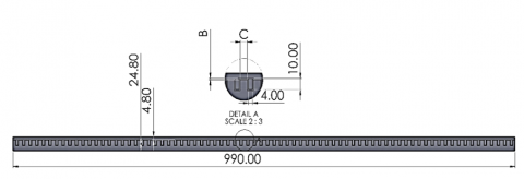
Solar panels, phase change materials, and heat sink fins were designed in Solidworks Software, 2019 Edition, a special program in engineering object design with high precision. It was taken into account that the design process took place in two stages. The first stage is to design the heat sink into a flat piece and attach it to the solar panel. Hence the phase-change material as in Figure 1. For the second stage, it represents changing the thickness of the heat sink fins sequentially with the phase change material, as shown in Figure 1.
Figure 1. Geometry shape
Where changing the dimensions of the fins was studied differently, a different thickness of fins was used for each case: 1 mm, 2 mm, and 3 mm, which represents the dimension B, and the distance between one fin and another is represented by the number C, which is in three dimensions: 4 mm, 8 mm, and 12 mm.
In the current study, PCM is considered a pure substance as the running liquid, and the characteristics of flow are assumed to be:
• Transient flow, three dimensional
• Newtonian
• Compressible
• Laminar.
The simulation process requires making an accurate mesh to solve complex equations, and this mesh needs to verify its parameters as the increase in the number of elements gives more accurate results, but at a certain limit. To ensure the reliability of the mesh, it is necessary to make the mesh independent, as shown in Table 1, where the value of element 98355 is used to obtain simulations with accurate results.
Table 1. Mesh indpendancy
|
Case |
Element |
Node |
Maximum Temperature (℃) |
|
1 |
17345 |
19565 |
45.85 |
|
2 |
21087 |
26257 |
44.79 |
|
3 |
54764 |
56217 |
44.73 |
|
4 |
98355 |
104468 |
44.72 |
Structured grids are successful for complex geometries, so for the above reasons, structured hexahedron grids were used in the current study (Figure 2).
Figure 2. Mesh generated
The solar radiation falling on the solar panel is its value in the summer and at one o'clock in the afternoon, at the height of its radiative effect, where the value of the incident solar radiation is 780 W/m2 projected on the outer surface of the solar panel. For heat flow and for heat to exit from the other side, convective heat transfer must be added with an air temperature of 25 degrees Celsius and a heat transfer coefficient of 5 W/m2. The initial state of the different used states is the natural temperature, which represents 25 degrees Celsius; the phase-changing material is completely rigid; and the flow velocity is 0 m/s. The material used for the fins is aluminum, and the PCM has a specific heat of 2000 J/kg K and a thermal conductivity of 0.2 W/m K.
4.1 Energy equation
The enthalpy of the material is computed as the sum of the sensible enthalpy, $h$, and the latent heat, $\Delta H$:
$H=h+\Delta H$ (1)
where,
$h=h_{\text {ref }}+\int_{T_{r e f}}^T c_p d T$ (2)
and
$\begin{array}{lll}\beta=0 & \text { if } & T<\mathrm{T}_{\text {solidus }} \\ \beta=1 & \text { if } & T>T_{\text {liquidus }} \\ \beta=\frac{T-T_{\text {solditus }}}{T_{\text {liquidus }} T_{\text {soldus }}} & \text { if } & T_{\text {solidus }}<\mathrm{T}<\mathrm{T}_{\text {liquidus }}\end{array}$ (3)
The latent heat content can now be written in terms of the latent heat of the material:
$\Delta H=\beta L$ (4)
The latent heat content can vary between zero (for a solid) and L (for a liquid). For solidification/melting problems, the energy equation is written as:
$\frac{\partial}{\partial t}(\rho H)+\nabla \cdot(\rho \vec{v} H)=\nabla \cdot(k \nabla T)+S$ (5)
where,
$H=$ enthalpy
$\rho=$ density
$\vec{V}=$ fluid velocity
$S=$ source term
4.2 Momentum equations
The enthalpy-porosity technique treats the sensitive district (a genuinely hardened region) as a vulnerable medium. The porosity in every cell is similar to the fluid in that cell. In a completely settled district, the porosity is tantamount to nothing, which sprinkles the speeds here. The energy sink because of the reduced porosity in the sensitive zone takes the following structure:
$S=\frac{(1-\beta)^2}{\left(\beta^3+\varepsilon\right)} A_{\text {mush }}\left(\vec{v}-\vec{v}_p\right)$ (6)
where, $\beta$ is the fluid volume part, $\varepsilon$ is a modest number $(0.001)$ to forestall division by nothing, $A_{\text {mush }}$ is the soft zone steady, and $\vec{v}_p$ is the strong speed because of the pulling of hardened material out of the space (likewise alluded to as the force speed).
4.3 Turbulence equations
Sinks are added to all of the irritation conditions in the fragile and cemented zones to address the presence of strong matter. The sink term is basically identical to the power sink term:
$S=\frac{(1-\beta)^2}{\left(\beta^3+\varepsilon\right)} A_{\text {mush }} \varphi$ (7)
where, $\varphi$ addresses the choppiness amount being settled $(k, \varepsilon$, $\omega$, etc.), and the soft zone steady, $A_{\text {mush}}$, is equivalent to the one utilized in Condition.
4.4 Species equations
Ansys natural figures the solids and liquids temperatures in a creature bunch mix as,
$\begin{gathered}T_{\text {solidus }}=T_{\text {melt }}+\sum_{\text {solutes }} m_i Y_i / K_i \\ T_{\text {liquidus }}=T_{\text {melt }}+\sum_{\text {solutes }} m_i Y_i\end{gathered}$ (8)
where, $K_i$ is the segment coefficient of solute $Y_i$ is the mass part of solute $i$, and $m_i$ is the slant of the liquidus surface regarding $Y_i$. Assuming the worth of the mass division $Y_i$ surpasses the worth of the eutectic mass part $Y_i$, then $Y_i$ is cut to $Y_i$ while computing the liquidus and solidus temperatures. It is accepted that the last species of material in the combination is dissolvable and that different species are solids.
Ansys familiar expects that you will enter a negative incentive for the liquidus slant of species $i\left(m_i\right)$. On the off chance that you input a positive incline for $m_i$, Ansys Familiar will ignore your feedback and on second thought compute it utilizing the Eutectic temperature $T_{\text {Eut }}$ and the Eutectic mass part $Y_{i, \text {Eut}}$:
$m_i=\frac{T_{\text {Eut }}-T_{\text {melt }}}{Y_{i_{\text {Eut }}}}$ (9)
Refreshing the fluid portion through condition can cause mathematical blunders and assembly challenges in multicomponent combinations. Overall, the fluid portion is refreshed as follows:
$\beta^{n+1}=\beta^n-\lambda \frac{a_p\left(T-T^*\right) \Delta t}{\rho V L=a_p \Delta t \frac{\partial T^*}{\partial \beta}}$ (10)
where, the superscript $n$ shows the accentuation number, $\lambda$ is a loosening up factor with a default worth of $0.9, a_p$ is the cell structure coefficient, $\Delta t$ is the time step, $\rho$ is the continuous thickness, $V$ is the cell volume, $T$ is the continuous cell temperature and $T^*$ is the association point temperature. Ansys natural offers two models for species disengagement at the little size, specifically the Switch rule and the Scheil rule. The past expects boundless scattering of the solute species in the solid, and the last choice acknowledges zero dispersal. For the Switch rule, the association point is not set in stone as follows:
$T^*=T_{\mathrm{melt}}+\sum_{i=0}^{N_s-1} m_i\left(\frac{Y_i}{K_i+\beta\left(1-K_i\right)}\right)$ (11)
where, $N_{\mathrm{s}}$ is the number of species.
The Scheil rule evaluates $T^*$ as:
X$T^*=T_{\text {melt }}+\sum_{i=0}^{N_s-1} m_i Y_i \beta^{K_i-1}$ (12)
For information about how back scattering (that is, a restricted proportion of the spread of the solute species) can be coordinated into the definition, see the section that follows.
For the Switch rule, species transport conditions are handled for indisputably the mass piece of species i, $Y_i$:
$\begin{gathered}\frac{\partial}{\partial t}\left(\rho Y_i\right)+\nabla \cdot\left(\rho\left[\beta \vec{v}_{l i q} Y_{i, l i q}+(1-\beta) \vec{v}_p Y_{i, s o l}\right]\right) \\ =-\nabla \cdot \vec{J}_i+R_i\end{gathered}$ (13)
For the Switch rule, species transport conditions are handled for the total mass piece of species i, $Y_i$:
$\begin{gathered}\frac{\partial}{\partial t}\left(\rho Y_i\right)+\nabla \cdot\left(\rho\left[\beta \vec{v}_{l i q} Y_{i, l i q}+(1-\beta) \vec{v}_p Y_{i, s o l}\right]\right) \\ =-\nabla \cdot \vec{J}_i+R_i\end{gathered}$ (14)
where, $R_i$ is the reaction rate and $\vec{J}_i$ is given by
$\vec{J}_i=-\rho\left[\beta D_{i, m, l i q} \nabla Y_{i, i i q}+(1-\beta) D_{i, m, s o l} \nabla Y_{i, s o l}\right]$ (15)
$\vec{v}_{l i q}$ is the speed of the liquid and $\vec{v}_p$ is serious areas of strength for the speed. $\vec{v}_p$ is set to nothing if pull speeds are avoided by the course of action. The liquid speed can be found from the ordinary (still hanging out there by the stream condition) as:
$\vec{v}_{l i q}=\frac{\left(\vec{v}-\vec{v}_p(1-\beta)\right)}{\beta}$ (16)
The fluid $\left(Y_{i, l i q}\right)$ and solid $\left(Y_{i, s o l}\right)$ mass portions are connected with one another by the parcel coefficient $K_i$:
$Y_{i, s o l}=K_i Y_{i, l i q}$ (17)
At the point when the Scheil model is chosen, Ansys Familiar addresses for $Y_{i, l i q}$ as the reliant variable:
$\begin{aligned} & \frac{\partial}{\partial t}\left(\rho Y_{i, l i q}\right)+\nabla \\ & \cdot\left(\rho\left[\beta \vec{v}_{l i q} Y_{i, l i q}+(1-\beta) \vec{v}_p Y_{i, s o l}\right]\right)=R_i \\ & +\nabla \cdot\left(\rho \beta D_{i, m, l i q} \nabla Y_{i, l i q}\right) \\ & -K_i Y_{i, l i q} \frac{\partial}{\partial t}(\rho(1-\beta))+\frac{\partial}{\partial t}\left(\rho(1-\beta) Y_{i, l i q}\right) \\ & \end{aligned}$ (18)
Numerous numerical techniques are used to solve the governing equations regulating heat transport, fluid dynamics, and phase change phenomena in the numerical research targeted at boosting solar panel thermal efficiency utilizing phase change materials (PCMs) and heatsinks. Due to its adaptability, capability to handle complicated geometries, and capacity to manage transient behavior, the Finite Volume Method (FVM) is one of these approaches that is often utilized. The governing partial differential equations (PDEs) are discretized across a computational domain that consists of control volumes using FVM. The domain's tiny, distinct areas where the conservation rules of mass, momentum, and energy are in effect are represented by these control volumes. FVM assures the conservation of mass and energy inside each control volume by discretizing the equations in this manner, offering precise and reliable answers to heat transfer issues.
PV panels are crucial for reducing the global energy crisis and addressing environmental concerns. However, the operating temperature of PV panels significantly impacts their performance, potentially reducing energy conversion efficiency and accelerating degradation. To enhance thermal performance, research has focused on phase change materials (PCMs) and heatsinks. Solidworks Software 2019 Edition was used to create solar panels, phase change materials, and heat sink fins. The design process was split into two phases, with fin thicknesses and distances considered. The phase-changing material is stiff. Aluminum is used for fins, and PCM has a thermal conductivity of 0.2 W/m K and a specific heat of 2000 J/kg K.
The main limitation of this work is that the simulation was in two-dimensional form because it takes a long time or a supercomputer to solve three-dimensional problems.
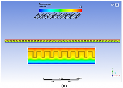
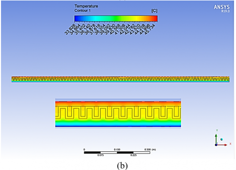
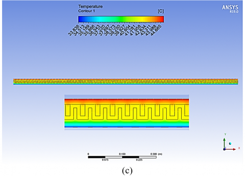
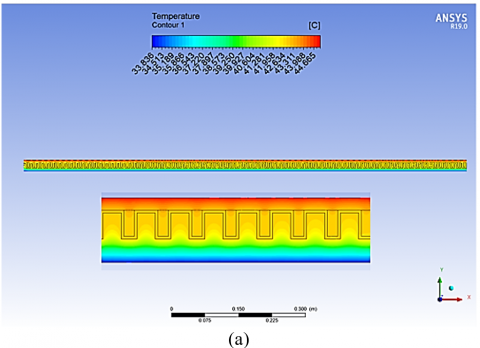
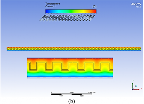
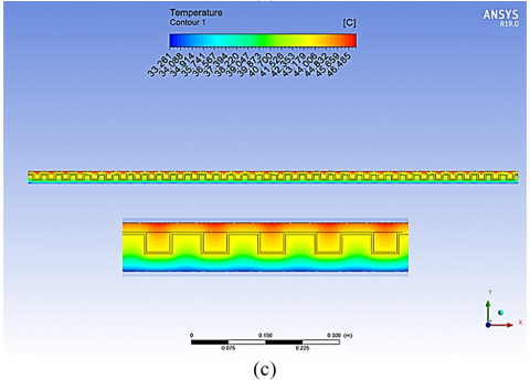
Figure 3. Temperature contour at deferent thickness of fin: (a) 1 mm; (b) 2 mm; (c) 3 mm
5.1 Effect of fins thickness
Changing the thickness of the fin helps greatly in understanding the process of transferring thermal energy from the surface of the solar panel and passing it to the phase change material. Where the fins play an important role in the thermal discharge of the phase change material and the thickness changes the pattern of this transfer.
Figure 3 shows the distribution of temperatures through the different thicknesses. Where it is noted that the increase in the thickness of the fin reduces the temperatures on the surface significantly. The thickness of 1 mm was the surface temperature of 46.950 degrees Celsius, while the thickness of 2 mm was the temperature of the surface of the plate at 45.734 degrees Celsius, or the best condition, which was at the thickness of 3 mm, where it went down to 44.665 degrees Celsius.
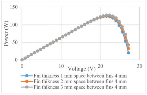
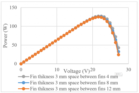
The benefit of reducing the temperatures on the surface of the solar panel is to obtain a high efficiency of the solar panel and to generate the largest possible capacity to satisfy the purpose for which it works. Figure 4 illustrates a power voltage diagram with varying fin thicknesses. It is noted that the value of the capacity increases with the increase in the thickness of the fin, and the reason for this is that the high thickness works to increase the heat transfer area.
Figure 4. Power voltage diagram with varying fin thickness
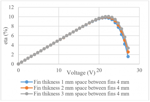
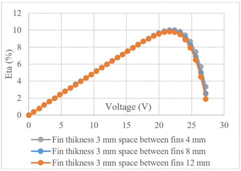
The basic principle for comparison and understanding of the case is to increase the electrical efficiency, which is the basis for understanding the improvement in temperature. Through Figure 5, it is noted that the value of efficiency increases with the increase in the thickness of the fin, as the efficiency reached 10.2% at a thickness of 3 mm, which is the highest case compared to the remaining cases.
Figure 5. Efficiency voltage diagram with varying fin thickness
5.2 Effect of fins space
Changing the distance between the fins reduces or increases the number of fins along the solar panel. As it is expected to obtain better results from decreasing the distance between the fins, as is the case in Figure 6, which shows the temperature gradient according to the distance between the fins. Which reached temperatures in the range of 4 mm to 44.665 degrees Celsius, and at 8 mm it was 45.694 degrees Celsius. Moreover, at a distance of 12 mm, the temperatures reached 46.485 degrees Celsius, which is considered the worst case for reaching the appropriate efficiency.
Figure 6. Temperature contour at deferent space between fins: (a) 4 mm, (b) 8 mm, (c) 12 mm
The advantage of lowering the temperature of the solar panel's surface is that it increases the panel's efficiency and produces as much energy as is feasible to fulfil its intended function. A power voltage diagram with variable fin spacing is shown in Figure 7. When the distance between the fins is changed, the number of fins along the solar panel grows, increasing the heat transfer area. This is why it is noticed that the value of the capacity increases with the increase in fin spacing.
Figure 7. Power voltage diagram with varying fin spacing
Increasing electrical efficiency is the fundamental idea behind comparison and comprehension of the case, and it forms the cornerstone of comprehending temperature improvement. Through Figure 8, it can be seen that the efficiency value rises as the fin spacing grows; for example, the efficiency reached 10.4% at a fin spacing of 4 mm, the highest case when compared to the other cases.
Figure 8. Efficiency voltage diagram with varying fin spacing
To evaluate the effect of heat sink design on the cooling and efficiency of PV panels integrated with PCM. A numerical model was developed to simulate the heat transfer and PCM melting in the heat sink. The effects of fin thickness and spacing were studied. Increasing fin thickness and decreasing fin spacing improved heat dissipation from the PV panel, reducing surface temperature by up to 46.4℃. This increased the electrical efficiency of the panel by up to 10.4%. The main limitation of this work is that the simulation was in two-dimensional form because it requires more time or a supercomputer to solve three-dimensional problems. Thus, the conclusions of this work are:
(1) Changing the thickness of the fin helps to understand the process of transferring thermal energy from the solar panel and passing it to the phase change material. The thickness of 1 mm was the surface temperature of 46.950 degrees Celsius, while the thickness of 2 mm was the temperature of the surface of the plate at 45.734 degrees Celsius. The best condition was at a thickness of 3 mm, where temperatures went down to 44.665 degrees Celsius.
(2) The benefit of reducing the temperatures on the surface of a solar panel is to obtain high efficiency and generate the largest possible capacity. A power voltage diagram with varying fin thickness shows that the value of the capacity increases with the increase in the thickness of the fin and that the high thickness works to increase the heat transfer area. The basic principle for comparison and understanding of the case is to increase the electrical efficiency, which is the basis for understanding the improvement in temperature. The efficiency reached 10.2% at a thickness of 3 mm, the highest case compared to the remaining cases.
(3) Changing the distance between the fins reduces or increases the number of fins along the solar panel, as it is expected to obtain better results. The temperature gradient according to the distance between fins varies, with temperatures ranging from 4 mm to 44.665 degrees Celsius, 8 mm to 45.694 degrees Celsius, and 12 mm to 46.485 degrees Celsius. This is considered the worst-case scenario for reaching the appropriate efficiency.
(4) The advantage of lowering the temperature of a solar panel's surface is to increase its efficiency and produce as much energy as possible. The efficiency value rises as the fin spacing grows, with 10.4% at a fin spacing of 4 mm being the highest case. Increasing electrical efficiency is the fundamental idea behind comparison and comprehension of the case, and it forms the cornerstone of comprehending temperature improvement.
[1] Duan, J. (2021). A novel heat sink for cooling concentrator photovoltaic system using PCM-porous system. Applied Thermal Engineering, 186: 116522. https://doi.org/10.1016/j.applthermaleng.2020.116522
[2] Rahmanian, S., Rahmanian-Koushkaki, H., Omidvar, P., Shahsavar, A. (2021). Nanofluid-PCM heat sink for building integrated concentrated photovoltaic with thermal energy storage and recovery capability. Sustainable Energy Technologies and Assessments, 46: 101223. https://doi.org/10.1016/j.seta.2021.101223
[3] Nižetić, S., Jurčević, M., Čoko, D., Arıcı, M. (2021). A novel and effective passive cooling strategy for photovoltaic panel. Renewable and Sustainable Energy Reviews, 145: 111164. https://doi.org/10.1016/j.rser.2021.111164
[4] Velmurugan, K., Kumarasamy, S., Wongwuttanasatian, T., Seithtanabutara, V. (2021). Review of PCM types and suggestions for an applicable cascaded PCM for passive PV module cooling under tropical climate conditions. Journal of Cleaner Production, 293: 126065. https://doi.org/10.1016/j.jclepro.2021.126065
[5] Siah Chehreh Ghadikolaei, S. (2021). Solar photovoltaic cells performance improvement by cooling technology: An overall review. International Journal of Hydrogen Energy, 46(18): 10939-10972. https://doi.org/10.1016/j.ijhydene.2020.12.164
[6] Ali, H.M. (2020). Recent advancements in PV cooling and efficiency enhancement integrating phase change materials based systems – A comprehensive review. Solar Energy, 197: 163-198. https://doi.org/10.1016/j.solener.2019.11.075
[7] Wongwuttanasatian, T., Sarikarin, T., Suksri, A. (2020). Performance enhancement of a photovoltaic module by passive cooling using phase change material in a finned container heat sink. Solar Energy, 195: 47-53. https://doi.org/10.1016/j.solener.2019.11.053
[8] Abdollahi, N., Rahimi, M. (2020). Potential of water natural circulation coupled with nano-enhanced PCM for PV module cooling. Renewable Energy, 147: 302-309. https://doi.org/10.1016/j.renene.2019.09.002
[9] Siahkamari, L., Rahimi, M., Azimi, N., Banibayat, M. (2019). Experimental Investigation on Using a Novel Phase Change Material (PCM) in Micro Structure Photovoltaic Cooling System. International Communications in Heat and Mass Transfer, 100: 60-66. https://doi.org/10.1016/j.icheatmasstransfer.2018.12.020
[10] Sarafraz, M.M., Safaei, M.R., Leon, A.S., Tlili, I., Alkanhal, T.A., Tian, Z., Goodarzi, M., Arjomandi, M. (2019). Experimental Investigation on Thermal Performance of a PV/T-PCM (Photovoltaic/Thermal) System Cooling with a PCM and Nanofluid. Energies, 12: 1-16. https://doi.org/10.3390/en12132572
[11] Salem, M.R., Elsayed, M.M., Abd-Elaziz, A.A., Elshazly, K.M. (2019). Performance enhancement of the photovoltaic cells using Al2O3/PCM mixture and/or water cooling-techniques. Renewable Energy, 138: 876-890. https://doi.org/10.1016/j.renene.2019.02.032
[12] Nada, S.A., El-Nagar, D.H., Hussein, H.M.S. (2018). Improving the thermal regulation and efficiency enhancement of PCM-integrated PV modules using nano particles. Energy Conversion and Management, 166: 735-743. https://doi.org/10.1016/j.enconman.2018.04.035
[13] Hasan, A., Sarwar, J., Alnoman, H., Abdelbaqi, S. (2017). Yearly energy performance of a photovoltaic-phase change material (PV-PCM) system in hot climate. Solar Energy, 146: 417-429. https://doi.org/10.1016/j.solener.2017.01.070
[14] Chandel, S.S., Agarwal, T. (2017). Review of cooling techniques using phase change materials for enhancing efficiency of photovoltaic power systems. Renewable and Sustainable Energy Reviews, 73: 1342-1351. https://doi.org/10.1016/j.rser.2017.02.001
[15] Stropnik, R., Stritih, U. (2016). Increasing the efficiency of PV panel with the use of PCM. Renewable Energy, 97: 671-679. https://doi.org/10.1016/j.renene.2016.06.011
[16] KoŚny, J., Biswas, K., Miller, W., Kriner, S. (2012). Field thermal performance of naturally ventilated solar roof with PCM heat sink. Solar Energy, 86(9): 2504-2514. https://doi.org/10.1016/j.solener.2012.05.020