Dhiyaa Sheltag*![]() | Saleem Khalefa Kadhim
| Saleem Khalefa Kadhim![]()
© 2024 The authors. This article is published by IIETA and is licensed under the CC BY 4.0 license (http://creativecommons.org/licenses/by/4.0/).
OPEN ACCESS
In the context of critical medical equipment, particularly ventilators, the Corona Virus Disease 2019 (COVID-19) pandemic has heightened the importance of reliable respiratory support systems. Ventilators, designed to aid patient breathing, confront the challenge of delivering consistent air pressure and flow. This study explores the effectiveness of two control methods in ventilator systems: conventional Proportional-Integral-Derivative (PID) control and an advanced nonlinear PID control. The former employs a fixed formula for system regulation, while the latter adopts an adaptive mechanism, offering potential improvements in responsiveness to patient-specific needs. This investigation centers on the formulation and generalization of a robust, calculus-based controller for ventilators, with a particular focus on the nonlinear control method. The efficiency of these control methods in ventilator units was assessed, comparing traditional PID and nonlinear PID controllers. It was found that both methods exhibited an equivalent error percentage between reference and actual air pressures, quantified at approximately 0.94 mbar. This similarity highlights the effectiveness of the nonlinear PID controller, matching the precision of the traditional approach. Crucially, the nonlinear PID controller demonstrated a faster response time, indicating an enhanced capability for rapid adjustments in response to sudden patient demand changes. This feature is particularly significant in critical care environments, where swift adaptation of ventilator settings is essential for patient safety. The study emphasizes the control systems of ventilators, rather than their complete mechanical design, with the term 'error' specifically referring to the variance between desired and actual air pressures. The results of this research suggest that the nonlinear PID controller represents a significant advancement over existing methods. Its rapid response capabilities offer a promising avenue for improving patient safety and adaptability in challenging clinical scenarios. The investigation underscores the potential of nonlinear PID control in ventilator systems, positioning it as a superior alternative in specific medical contexts. This work contributes to the ongoing development of more responsive and patient-tailored approaches in mechanical ventilation, highlighting the convergence of advanced control theory and practical healthcare applications.
ventilator, closed-loop feedback, mechanical ventilation, Corona Virus Disease 2019, proportional-integral-derivative control, nonlinear proportional-integral-derivative control
Ventilators, crucial in medical settings for aiding individuals with compromised respiratory functions, operate based on the patient's level of consciousness and breathing capacity. These devices typically employ two distinct methodologies: volume ventilation and pressure ventilation. In volume ventilation, a consistent amount of air is delivered, albeit with variable pressure, enabling the device to exert the necessary pressure to achieve the requisite air volume. However, this elevated pressure may pose risks of alveolar damage [1]. The focus of this study is to regulate air pressure in ventilators to maintain airflow that aligns with patient needs, minimizing fluctuations and excesses in the control signal. In addressing ventilator control, this study compares two prevalent methods: PID control and nonlinear PID control. The aim is to discern the efficacy of these methods in producing an effective control signal with minimal distortion. The impetus for this research is grounded in the critical role of ventilators in patient care and the inherent challenges in achieving precise, adaptive control.
Borrello [2] posited that the human lung functions analogously to an electrical circuit, characterized by resistance and capacitance (RC). An adaptive Proportional Integral (PI) controller has been proposed for managing the dynamic changes in the RC circuit during respiration. Abolghasemi and Ferdowsi [3] employed a PID controller in a mechanical ventilator, highlighting its effectiveness in maintaining the desired ventilation rate. However, they emphasized the necessity of appropriate gain selection for optimal control. Similarly, Li and Li [4] implemented a PID controller to regulate ventilator pressure output, observing its efficacy but cautioning against potential overshooting and instability due to gain tuning. In lieu of traditional gain tuning, an optimization approach has been explored for PID control in artificially ventilated respiratory systems. The linear nature of PID control, though widely adopted, faces challenges in addressing system nonlinearities and disturbances. Even with meticulous tuning, capturing dynamic patient breathing patterns remains a complex task. Conversely, nonlinear PID control offers adaptability but introduces complexities in selecting suitable nonlinear functions and in managing increased system intricacies. Bisht et al. [5] found that a nonlinear PID controller yielded more precise and stable control in pressure-controlled ventilators, especially in the presence of disturbances. Khakpour et al. [6] demonstrated the superiority of nonlinear PID control in maintaining desired tidal volumes in volume-controlled ventilators, as opposed to traditional PID control.
The selection of an appropriate nonlinear function for mapping the error signal to control output remains a challenge in nonlinear PID control, compounded by the potential increase in controller complexity. Both PID and nonlinear PID controls have been validated as effective for ventilator control in various studies. However, the challenges in optimal gain and nonlinear function selection, coupled with the need for stable and accurate control amidst disturbances and nonlinear dynamics, are still prevalent. The dynamic nature of human lung function during inhalation and exhalation introduces complexities in ventilator control, particularly when model uncertainties are not adequately addressed [7]. Model-based control strategies, such as Model Predictive Control (MPC), have gained prominence in the realm of mechanical ventilation. Li and Haddad [8] proposed an MPC strategy for a multi-compartment respiratory system, utilizing a mathematical model to develop a controller capable of tracking desired tidal volumes and oxygenation trajectories. This MPC controller, operating on a predictive model, optimized control inputs over a finite horizon, factoring in constraints on inputs and system states. It was demonstrated that this MPC controller outperformed a traditional PID controller in tracking performance, particularly under model uncertainties and disturbances.
Reinders et al. [9] introduced a repetitive control strategy to enhance mechanical ventilation. Their approach focused on improving the accuracy of tidal volume and respiratory rate tracking by exploiting the cyclic nature of ventilation. The strategy, tested through simulations and experiments on a mechanical ventilator, achieved superior tracking accuracy and reduced variability in tidal volume and respiratory rate compared to conventional PID and PI control methods. Hunnekens et al. [10] proposed a variable-gain control strategy for respiratory systems, aimed at enhancing tracking performance by dynamically adjusting control system gains according to operating conditions. Simulations and experiments on a mechanical ventilator demonstrated that this variable-gain strategy surpassed traditional control methods, such as PID and PI control, in tracking accuracy and adaptability to changing conditions.
Despite these advancements, previous studies have not comprehensively analyzed the control signal of the PID controller or diagnosed its weaknesses. Therefore, this research undertakes a thorough examination of the PID control signal, comparing it with nonlinear PID to discern variations in control signal behavior. The proposed method incorporates an advanced algorithm that adapts to patient-specific requirements while minimizing overshoots and response lags. By integrating real-time feedback mechanisms and harnessing the strengths of both PID and nonlinear PID, this method aims to achieve unparalleled control precision. This study represents a novel approach in ventilator control research. While previous investigations have primarily focused on PID controllers, this work delves into the evaluation of nonlinear PID controllers. The aim is to facilitate smoother respiratory transitions and robustly respond to unpredictable changes. A key observation is that prior research has largely overlooked the detailed analysis of the PID control signal’s behavior. This study contrasts conventional PID with nonlinear PID, highlighting subtle yet critical variations in control signal dynamics. Furthermore, it introduces a groundbreaking methodology centered on stimulus-response dynamics, enabling designers to develop a more sequential and effective control system for ventilation units. This approach is anticipated to surpass the limitations encountered in previous methods, promoting both patient safety and operational efficiency.
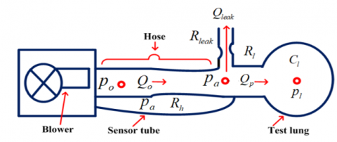
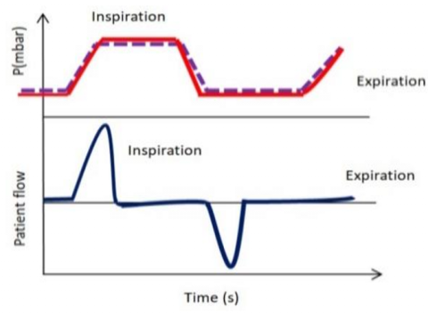
In Figure 1, a schematic representation of a respiratory system is depicted, illustrating pressures (marked in red), flows (indicated in blue), resistances, and compliance. The mechanical ventilation device, comprising an electrically powered blower unit, generates the requisite pressure for patient lung inflation (Po) via a hose medium. Mathematical models have been instrumental in resolving complex engineering challenges [11, 12] and are similarly utilized to elucidate lung mechanics and enhance mechanical ventilation therapy [13]. A prevalent approach in existing literature involves the use of a single-compartment lung model, accounting for lung elastance (inverse of compliance) and airway resistance [14]. The foundational assumptions for this study are twofold: firstly, the resistances of the lung, hose, and leak are considered constant during each breath cycle, aligning with typical clinical scenarios. Secondly, lung compliance is treated as a fixed parameter, acknowledging potential inter-patient variability. These assumptions are based on the study [10], and parameters are primarily derived from clinical literature and experimental data calibration [15].
Figure 1. Schematic of a mechanical ventilation unit
In the schematic (Figure 1), air is inhaled at a rate of $Q_o$ and exhaled at a rate of $Q_{\text {leak }}$ through a leaky hose, leaving $Q_p$ as the net exhaled airflow [16].
$Q_p=Q_o-Q_{\text {leak }}$ (1)
The airflow from the blower to the lung is analogous to current flow in an electric wire, where pressure is akin to electric voltage. This analogy allows for the conceptualization of the respiratory system as an electric circuit, where resistances represent airway obstructions, and the potential difference is denoted by pressures. The patient airflow depicted in Figure 1 can be expressed using an analogy to Ohm's Law [17]. This analogy is particularly relevant in understanding airflow and pressures in respiratory systems, especially for patients with increased airway resistance conditions like asthma or chronic obstructive pulmonary disease (COPD). Inside the ventilation unit, a pressure sensor measures the airway pressure, denoted as Pa.
The control system’s objective is to ensure that the measured pressure aligns with the desired set point Pr. Hence, the error equation is defined as follows [14]:
$e=P_r-P_a$ (2)
Assuming identified standard resistances for the hose, leak channel, and patient lungs, the flow rates of the blower, patient, and leak are expressed as functions of these resistances [14]:
$Q_o=\frac{P_o-P_a}{R_h}$ (3)
$Q_{\text {leak }}=\frac{P_a}{R_{\text {leak }}}$ (4)
$Q_p=\frac{P_a-P_{\text {lung }}}{R_{\text {lung }}}$ (5)
Dynamics of the lung pressure Plung adhere to the following differential equation:
$P_{\text {lung }}=\frac{1}{C_{\text {lung }}} \cdot Q_p$ (6)
In Eq. (5), Plung is analogous to voltage, while Qp can be compared to current. Integrating Eqs. (5) and (6) yields:
$P_{\text {lung }}=\frac{P_a-P_{\text {lung }}}{C_{\text {lung }} \cdot R_{\text {lung }}}$ (7)
To determine airway pressure Pa, the equation is formulated by substituting Eqs. (3)-(5) into Eq. (1):
$\frac{P_a-P_{\text {lung }}}{R_{\text {lung }}}=\frac{P_o-P_a}{R_h}-\frac{P_a}{R_{\text {leak }}}$ (8)
$\frac{P_a}{R_{\text {lung }}}-\frac{P_{\text {lung }}}{R_{\text {lung }}}=\frac{P_o}{R_h}-\frac{P_a}{R_h}-\frac{P_a}{R_{\text {leak }}}$ (9)
$\frac{P_a}{R_{\text {lung }}}+\frac{P_a}{R_h}+\frac{P_a}{R_{\text {leak }}}=\frac{P_o}{R_h}+\frac{P_{\text {lung }}}{R_{\text {lunq }}}$ (10)
$P_a\left(\frac{1}{R_{\text {lung }}}+\frac{1}{R_h}+\frac{1}{R_{\text {leak }}}\right)=\frac{P_o}{R_h}+\frac{P_{\text {lung }}}{R_{\text {lung }}}$ (11)
$P_a=\frac{\frac{1}{R_h} \cdot P_o+\frac{1}{R_{\text {lung }}} \cdot P_{\text {lung }}}{\frac{1}{R_{\text {lung }}}+\frac{1}{R_h}+\frac{1}{R_{\text {leak }}}}$ (12)
Upon substituting the airway pressure expression from Eq. (12) into the differential equation for lung dynamics (Eq. (7)), a revised equation is formulated:
$P_{\text {lung }}=\frac{-P_{\text {lung }}\left(\frac{1}{R_h}+\frac{1}{R_{\text {leak }}}\right)+\frac{1}{R_h} \cdot P_o}{C_{\text {lung }} \cdot R_{\text {lung }}\left(\frac{1}{R_{\text {lung }}}+\frac{1}{R_h}+\frac{1}{R_{\text {leak }}}\right)}$ (13)
With Eqs. (5), (12) and (13) considered, the combined system of the patient and hose is expressible as a linear state-space system, where Po serves as the input, $\left[\begin{array}{l}P_a \\ Q_p\end{array}\right]$ the output, and Plung the state.
$P_{\text {lung }}=A_h P_{\text {lung }}+B_h P_o$ (14)
$\left[\begin{array}{l}P_a \\ Q_p\end{array}\right]=C_h P_{\text {lung }}+D_h P_o$ (15)
where,
$A_h=-\frac{\frac{1}{R_h}+\frac{1}{R_{\text {leak }}}}{C_{\text {lung }} \cdot R_{\text {lung }}\left(\frac{1}{R_{\text {lung }}}+\frac{1}{R_h}+\frac{1}{R_{\text {leak }}}\right)}$ (16)
$B_h=\frac{\frac{1}{R_h}}{C_{\text {lung }} \cdot R_{\text {lung }}\left(\frac{1}{R_{\text {lung }}}+\frac{1}{R_h}+\frac{1}{R_{\text {leak }}}\right)}$ (17)
$C_h=\left[\begin{array}{c}\frac{\frac{1}{R_{lung}}}{\frac{1}{R_{\text {lung }}}+\frac{1}{R_{\text {h}}}+\frac{1}{R_{\text {leak }}}} \\ -\frac{\frac{1}{R_h}+\frac{1}{R_{\text {leak }}}}{R_{\text {lung }}\left(\frac{1}{R_{\text {lung }}}+\frac{1}{R_{\text {h}}}+\frac{1}{R_{\text {leak }}}\right)}\end{array}\right]$ (18)
$D_h=\left[\begin{array}{c}\frac{\frac{1}{R_{h}}}{\frac{1}{R_{\text {lung }}}+\frac{1}{R_{\text {h}}}+\frac{1}{R_{\text {leak }}}} \\ -\frac{\frac{1}{R_h}}{R_{\text {lung }}\left(\frac{1}{R_{\text {lung }}}+\frac{1}{R_{\text {h}}}+\frac{1}{R_{\text {leak }}}\right)}\end{array}\right]$ (19)
Additionally, this system can be represented in transfer function notation:
$H(s)=C_h \frac{1}{\left(S I-A_h\right)} B_h+D_h$ (20)
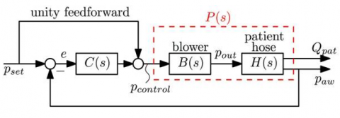
The blower system is designed to produce the desired module output pressure Po. Based on a steady-state characteristic, the blower's qualities have been defined to map the output pressure target Pcontrol(s) to the actual output pressure Po, yielding a unity gain, as depicted in Figure 2. However, the blower is a dynamic system with inherent inertia, resulting in a high-frequency roll-off similar to a servo system, which utilizes negative feedback for precise motion control.
Figure 2. Linear controller employed in a closed-loop control system C(s)
Figure 2 illustrates a second-order system characterized by two poles, with some second-order systems also possessing one or two zeros [18]. To elucidate the control system response, the standard responses of a second-order system to step, ramp, and impulse inputs are examined. The blower is conceptualized as a second-order system analogous to a servo system. This introduction underscores the nonlinear dynamics present in the respiratory system, a critical consideration in clinical settings where linear responses do not always suffice.
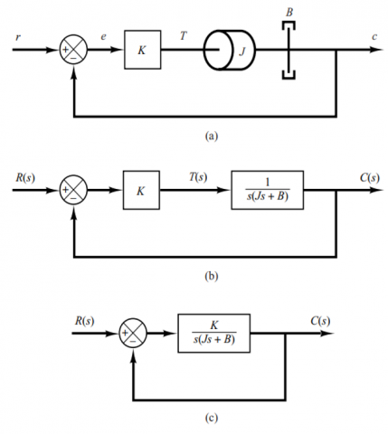
Figure 3(a) showcases a servo system comprising load elements, such as inertia and viscous-friction components, alongside a proportional controller. Here, the output position c corresponds to the input position r. The governing equation for the load elements is:
$J \ddot{c}+B \dot{c}=T$ (21)
where, T denotes the torque generated by the proportional controller with gain K, J represents the mass moment of inertia matrix, and B is the viscosity coefficient. Applying the Laplace transform to Eq. (21), given zero initial conditions, yields:
$J s^2 C(s)+B s C(s)=T(s)$ (22)
The transfer function linking C(s) and T(s) is:
$\frac{C(s)}{T(s)}=\frac{1}{s(J s+B)}$ (23)
The transfer function represented in Figure 3(a) is reinterpreted in Figure 3(b) and further modified in Figure 3(c). From these representations, the closed-loop transfer function is derived as:
$\frac{C(s)}{R(s)}=\frac{K}{J S^2+B s+K}=\frac{K / J}{s^2+(B / J) s+(K / J)}$ (24)
Figure 3. Servo system in (a); its block diagram in (b); and the simplified block diagram in (c) [18]
The step response of a second-order system is derived from the closed-loop transfer function, as depicted in Figure 3(c). The pertinent equation is formulated as follows:
$\frac{C(s)}{R(s)}=\frac{K}{J S^2+B s+K}$ (25)
This equation can also be represented alternatively:
$\frac{C(s)}{R(s)}=\frac{K / J}{\left[s+\frac{B}{2 J}+\sqrt{\left.\left(\frac{B}{2 J}\right)^2-\frac{K}{J}\right]\left[s+\frac{B}{2 J}-\sqrt{\left(\frac{B}{2 J}\right)^2-\frac{K}{J}}\right.}\right.}$ (26)
In transient-response analysis, the closed-loop poles are expressed as complex conjugates when $B^2-4 J K<0$, whereas for $B^2-4 J K \geq 0$, they are real. The expression is conveniently written as:
$\frac{K}{J}=\omega_n^2, \frac{B}{J}=2 \zeta \omega_n=2 \sigma$ (27)
where, $\sigma$ is termed as the attenuation; $\omega_n$ represents the undamped natural frequency; and $\zeta$ is the damping ratio of the system. The damping ratio is defined as the ratio of the actual damping $B$ to the critical damping $B_c=2 \sqrt{J K}$ or
$\zeta=\frac{B}{B_C}=\frac{B}{2 \sqrt{JK}}$ (28)
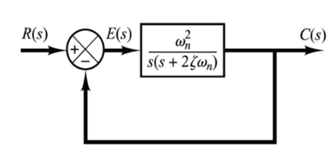
Figure 4. Representation of a second-order system [16]
The closed-loop transfer function of the system, as illustrated in Figure 3(c), can be expressed in terms of $\zeta$ and $\omega_n$, and subsequently transformed into the format depicted in Figure 4. The resulting transfer function for $C(s) / R(s)$, derived from Eq. (24), is expressed as:
$\frac{C(s)}{R(s)}=\frac{\omega_n^2}{s^2+2 \zeta \omega_n s+\omega_n^2}$ (29)
This equation typifies the form of a second-order system.
In the analysis of second-order systems, two critical parameters $\zeta$ and $\omega_n$ are employed for explication. It is observed that when $0<\zeta<1$, the closed-loop poles of the system are complex conjugates and are located in the left-half of the s-plane.
To analyze the system's response to a unit-step input, the case where the system is critically damped $(\zeta 1)$ is considered. Assuming that the experimental blower has a damping ratio of $\zeta=1$ and a natural frequency of $\omega_n=2 \pi / 30$, as illustrated in Figures 5 and 6 , the equation is:
$B_{(s)}=\frac{P_{o(s)}}{P_{\text {control }(s)}}=\frac{w_n^2}{s^2+2 \zeta w_n s+w_n^2}$ (30)
The state-space form of Eq. (30) is delineated as follows:
$\left.\begin{array}{c}X_b=A_b X_b+B_b P_{\text {control }} \\ P_o=C_b X_b\end{array}\right\}$ (31)
with state $X_b \in R_2$, output $P_{\text {out }}$, and control input $p_{\text {contrell }}$, the system matrices are detailed as:
$B_{(s)}=\frac{P_{o(s)}}{P_{\text {control }(s)}}=\frac{w_n^2}{s^2+2 \zeta w_n s+w_n^2}$ (32)
Eq. (32) is equivalent to Eq. (33):
$B_s=\frac{X(s)}{U(s)} * \frac{y(s)}{X(s)}$ (33)
${{B}_{s}}=\frac{y~\left( s \right)}{U~\left( s \right)}=\frac{\omega _{n}^{2}~}{{{s}^{2}}+2\zeta ~{{\omega }_{n}}s+\omega _{n~}^{2}}$ (34)
$\frac{X~\left( s \right)}{U~\left( s \right)}=\frac{1}{{{s}^{2}}+2\zeta ~{{\omega }_{n}}s+\omega _{n}^{2}}$ (35)
$U\left( s \right)=X\left( s \right){{s}^{2}}+2X\left( s \right)\zeta ~{{\omega }_{n}}s+X\left( s \right)\omega _{n}^{2}$ (36)
Applying the Laplace $\left(\mathcal{L}^{-1}\right)$ transformation to Eq. (36) yields:
$U\left( t \right)=\overset{\ddot{\ }}{\mathop{X\left( t \right)}}\,+2\zeta {{\omega }_{n}}+\dot{X}\left( t \right)+X\left( t \right)\omega _{n}^{2}$ (37)
$U=\overset{\ddot{\ }}{\mathop{X}}\,+2\zeta ~{{\omega }_{n}}+\dot{X}+X~\omega _{n}^{2}$ (38)
Eq. (38) elucidates the nonlinear dynamics inherent in the respiratory system. When denoting the state variable for the state equation [19, 20], the differential equation is expressed as:
${{X}_{2}}=X$ (39)
${{X}_{1}}=\overset{\ddot{\ }}{\mathop{X}}\,=\overset{}{\mathop{{{X}_{2}}}}\,$ (40)
$\overset{}{\mathop{{{X}_{1}}}}\,=\overset{\ddot{\ }}{\mathop{X}}\,$ (41)
$\overset{\ddot{\ }}{\mathop{X}}\,=-2~\zeta ~{{\omega }_{n}}-\dot{X}-X~\omega _{n}^{2}+U$ (42)
$\dot{X}={{X}_{1}}$ (43)
$\overset{\ddot{\ }}{\mathop{X}}\,=-2~\zeta ~{{\omega }_{n}}-{{X}_{1}}-{{X}_{2}}~\omega _{n}^{2}+U$ (44)
$\left[\begin{array}{l}\ddot{X} \\ \dot{X}\end{array}\right]=\left[\begin{array}{cc}-2 \zeta \omega_n & -\omega_n^2 \\ 1 & 0\end{array}\right]\left[\begin{array}{l}X_1 \\ X_2\end{array}\right]+\left[\begin{array}{l}1 \\ 0\end{array}\right] U$ (45)
$\frac{Y~\left( s \right)}{X~\left( s \right)}=\omega _{n}^{2}Y\left( s \right)=X\left( s \right)\omega _{n}^{2}$ (46)
The Laplace $({{\mathcal{L}}^{-1}})$ transformation applied to Eq. (46) results in:
$Y~\left( t \right)=X~\left( t \right)~\omega _{n~}^{2}$ (47)
$Y={{X}_{2}}~~\omega _{n~}^{2}$ (48)
$Y=\left[\begin{array}{ll}0 & \omega_n^2\end{array}\right]\left[\begin{array}{l}X_1 \\ X_2\end{array}\right]$ (49)
$\therefore A_b=\left[\begin{array}{cc}-2 \zeta \omega_n & -\omega_n^2 \\ 1 & 0\end{array}\right]$ (50)
$B_b=\left[\begin{array}{l}1 \\ 0\end{array}\right]$ (51)
$C_b=\left[\begin{array}{ll}0 & \omega_n^2\end{array}\right]$ (52)
${{D}_{b}}=\left[ 0 \right]$ (53)
The plant P(s), subject to feedback control, is articulated in a general state-space form by amalgamating Eq. (10), which delineates the patient-hose system dynamics, with Eq. (12), elucidating the blower dynamics as illustrated in Figure 2. This formulation is expressed as follows:
$X_p=\left[\begin{array}{c}X_b \\ P_{\text {lung }}\end{array}\right]=\underbrace{\left[\begin{array}{cc}A_b & 0 \\ B_h C_b & A_h\end{array}\right]}_{A_p} \underbrace{\left[\begin{array}{c}X_b \\ P_{\text {lung }}\end{array}\right]}_{B_p}+\left[\begin{array}{c}B_b \\ 0\end{array}\right] \cdot P_{\text {control }}$ (54)
$Z=\left[\begin{array}{c}P_a \\ Q_p\end{array}\right]=\underbrace{\left[\begin{array}{ll}D_h C_b & C_h\end{array}\right]}_{C_p}\left[\begin{array}{c}X_b \\ P_{\text {lung }}\end{array}\right]$ (55)
$P_{(s)}=\left[\begin{array}{l}P_{p(s)} \\ P_{Q(s)}\end{array}\right]=B_{(s)} H_{(s)}=C_p\left(S I-A_p\right)^{-1} B_p$ (56)
Table 1 enumerates the specifications of the ventilator unit [10]. Utilizing MATLAB's response optimization toolbox, the controllers' settings were adjusted to optimize performance for the reference signal Pr. Table 2 presents the finely-tuned settings of these controllers.
The ventilator underwent testing under the following scenarios:
·Application of set system parameters to evaluate performance under ideal conditions.
·Operation with an unknown parameter to assess system robustness.
Table 1. Parameters of the ventilator system [10]
|
Name |
Value |
Unit |
Parameter |
|
Rlung |
0.005 |
mbar/(mL⁄s) |
Lung resistance |
|
Clung |
20 |
mL/mbar |
Lungs compliance (Capacitance) |
|
Rleak |
0.06 |
mbar/(mL⁄s) |
Leak resistance |
|
Rh |
0.0045 |
mbar/(mL⁄s) |
Hose resistance |
|
wn |
2π60 |
rad/s |
Undamped natural frequency |
|
$\zeta=1$ |
1 |
mbar/(mL⁄s) |
damping ratio |
Table 2. Control system parameters [15]
|
PI |
Value |
|
kp |
3 |
|
ki |
250 |
Validation tests were conducted to ascertain the model's fidelity. Experimental setups, replicating the mathematical representation under controlled conditions, were aligned closely with the model’s predictions. Additionally, comparisons with documented data from previous studies [15] demonstrated congruence, thereby reinforcing the model’s credibility.
$\begin{aligned} & :: A_h=-\frac{\frac{1}{0.0045}+\frac{1}{0.06}}{0.005 * 20\left(\frac{1}{0.005}+\frac{1}{0.0045}+\frac{1}{0.06}\right)}=-\frac{238.89}{43.89}=-5.443, \\ & B_h=\frac{\frac{1}{0.0045}}{0.005 * 20\left(\frac{1}{0.005}+\frac{1}{0.0045}+\frac{1}{0.06}\right)}=\frac{222.222}{43.89}=5.0632\end{aligned}$
$C_h=\left[\begin{array}{c}\frac{\frac{1}{0.005}}{\frac{1}{0.005}+\frac{1}{0.0045}+\frac{1}{0.06}} \\ -\frac{\frac{1}{0.0045}+\frac{1}{0.06}}{0.005\left(\frac{1}{0.005}+\frac{1}{0.0045}+\frac{1}{0.06}\right)}\end{array}\right]=\left[\begin{array}{c}0.4557 \\ -108.8615\end{array}\right]$,
$D_h=\left[\begin{array}{c}\frac{\frac{1}{0.0045}}{\frac{1}{0.005}+\frac{1}{0.0045}+\frac{1}{0.06}} \\ \frac{\frac{1}{0.0045}}{0.005\left(\frac{1}{0.005}+\frac{1}{0.0045}+\frac{1}{0.06}\right)}\end{array}\right]=\left[\begin{array}{l}0.50633 \\ 101.266\end{array}\right]$
$A_b=\left[\begin{array}{cc}-376.8 & -35494.56 \\ 1 & 0\end{array}\right], B_b=\left[\begin{array}{l}1 \\ 0\end{array}\right], C_b=\left[\begin{array}{ll}0 & 35494.56\end{array}\right]$
$A_p=\left[\begin{array}{ccc}-376.8 & -35494.56 & 0 \\ 1 & 0 & 0 \\ 0 & 179716.0562 & -5.443\end{array}\right]$,
$C_p=\left[\begin{array}{ccc}0 & 17971.96056 & 0.4557 \\ 0 & 3594392.113 & -108.8615\end{array}\right]$
The control system design aims to fulfill dual objectives: (i) maintaining the patient's airflow Qp within acceptable limits to ensure comfort and safety, and (ii) regulating the airway pressure Pa to adapt to varying patient conditions and external disturbances. The primary goal of the closed-loop control system is the smooth and consistent delivery of the patient's airflow by regulating airway pressure. Selection of an appropriate control law is critical for ensuring patient safety, necessitating a control system that can rapidly and smoothly modulate air pressure while minimizing overshoots and oscillations in control excitation signals. Initially, a robust controller utilizing integer calculus is developed, inspired by the objective of achieving smooth regulation of patient pressure and flow, as illustrated in Figure 5.
Figure 5. Mechanical ventilation breathing cycle of a patient [15]
Theoretical framework and equations
Eqs. (14) and (15) are rewritten as follows:
$P_{\text {lung }}^\cdot=A_h P_{\text {lung }}+B_h P_o$ (57)
$P_a=C_{h 1} P_{l u n g}+D_{h 1} P_o$ (58)
$Q_p=C_{h 2} P_{\text {lung }}+D_{h 2} P_o$ (59)
Modeling the blower system
The blower system’s transfer function is represented as:
$\frac{P_o}{P_C}=\frac{(2 \pi 30)^2}{s^2+4 \pi 30 s+(2 \pi 30)}$ (60)
A universal first-order blower system model with a single pole is expressed in the following equation [21]:
$\frac{P_o}{P_c}=\frac{k}{s+a}$ (61)
In Eq. (61), parameters $k$ and $a$ are calculated using a response optimization toolbox to ensure minimal deviation between the outputs of Eqs. (60) and (61). Based on insights from the study, these parameters are determined as $k=80$ and $a=80$, effectively approximating the true second-order dynamics as evidenced by data from the study [17].
State space representation of the blower system
The essence of the blower system’s behavior is encapsulated in the following state space representation, derived from Eq. (61) and the specified parameters:
$\dot{P}_o=-a P_o+K P_c$ (62)
The outcomes of the investigations conducted in the preceding sections can be succinctly summarized as follows: $a=80, K=80, A_h=-5.443, B_h=5.063, C_{h 1}=0.45, D_{h 1}=0.5063$, $C_{h 2}=108.862, D_{h 2}=1$ $C_{h 2}=-108.862, D_{h 2}=101.27$.
The system outputs associated with the error e are given by [22]:
Derivation and control equations
The airway pressure error is formulated as:
$e=P_r-P_a$ (63)
where, $P_r$ represents the reference pressure and $P_a$ the airway pressure.
$P_c=U$ (64)
Eq. (58) is further derived to yield:
$\dot{P}_a=C_{h 1} P_{l u n g}+D_{h 1} \dot{P}_o$ (65)
Substituting Eqs. (57) and (62) into Eq. (65) results in:
$\dot{P}_a=C_{h 1}\left(A_h P_{l u n g}+B_h P_o\right)+D_{h 1}\left(-a P_o+K P_c\right)$ (66)
This equation can be concisely represented as:
$\begin{gathered}\dot{P}_a=C_{h 1} A_h P_{l u n g}+C_{h 1} B_h P_o-D_{h 1} a P_o \\ +D_{h 1} K P_c=-\mu e-\beta \int e\end{gathered}$ (67)
PID control equation
The PID control equation, crucial for system performance, is defined as:
$\left.\begin{array}{c}\mathcal{U}=-\frac{1}{D_{h 1} K} \\ \left(-\mu e-\beta \int e-a c_1 p_{\text {lung }}-b_1 c_1 P_o+a d_1 P_o\right) \\ \mu=1, \int e=3\end{array}\right\}$ (68)
Nonlinear PID control equation
For systems requiring enhanced precision, the nonlinear PID control equation is introduced:
$\begin{gathered}u=-\frac{1}{\mathrm{D}_{\mathrm{h} 1} \mathrm{~K}} \\ \left.\left(-\mu \mathrm{e}-\beta \int \tan ^{-1}(\gamma e(t)) d t-\mathrm{ac}_1 \mathrm{p}_{\text {lung }}-\mathrm{b}_1 \mathrm{c}_1 \mathrm{P}_{\mathrm{o}}+\mathrm{ad}_1 \mathrm{P}_{\mathrm{o}}\right)\right\} \\ \mu=1, \int \mathrm{e}=3\end{gathered}$ (69)
Compared to traditional ventilation control systems, the proposed method offers advantages such as faster response times, improved adaptability to patient conditions, and a more robust response to external disturbances, thereby enhancing patient safety and comfort.
Simulations using MATLAB and Simulink (Version R2022a), with the Control System Toolbox, were conducted. A range of patient breathing patterns, from relaxed to rapid shallow breathing, was modeled to evaluate the controller’s performance under diverse conditions.
Performance was assessed based on key metrics: settling time, overshoot, and steady-state error, crucial for gauging the system's efficacy in reaching and maintaining the desired state.
Section 3 presented the control modeling for the design of PID and nonlinear PID control models. In the context of nonlinear PID control for ventilator systems, the challenges are twofold: selecting an appropriate nonlinear function to map the error signal to the control output, and managing the increased complexity due to the incorporation of nonlinear elements [23]. Additionally, it is crucial to choose suitable controller gains and nonlinear functions while ensuring stable and accurate control in the presence of disturbances and nonlinear dynamics. To solve the control equations, both PID and nonlinear PID control models were utilized, and MATLAB code was developed for this purpose.
4.1 Comparison between PID and nonlinear PID
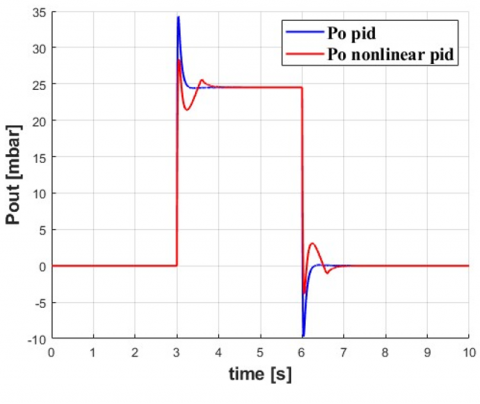
This section discusses the results obtained from the PID and nonlinear PID control. Figure 6 illustrates that the nonlinear control system exhibits greater sensitivity to disturbances and changes in the process variable. This increased sensitivity may stem from the use of more complex mathematical models in nonlinear PID controllers, potentially leading to more fluctuations and less stability.
Figure 6. Pout at PID and nonlinear PID control
In the comparative analysis of PID and nonlinear PID control systems, it has been observed that when a PID control system exhibits more oscillations than its nonlinear counterpart, it indicates a lesser efficacy in managing complex and highly variable systems. This phenomenon can be attributed to the intrinsic characteristics of the PID controller, which establishes a linear correlation between the error signal and the control output. Such a linear approach may not adequately capture the nonlinear dynamics inherent in certain systems.
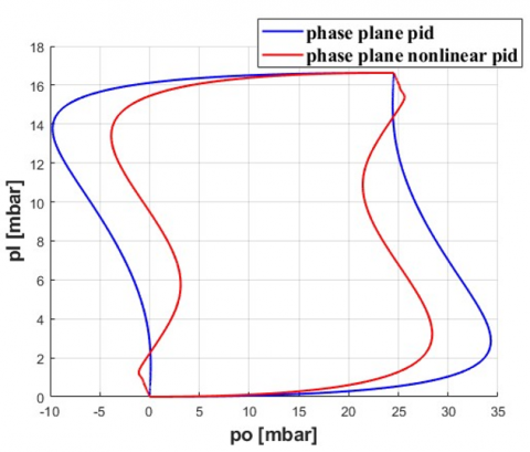
Furthermore, Figure 7 indicates that the phase plane in a nonlinear PID control system covers a smaller area than a PID control system. This observation suggests that the nonlinear controller might possess more limited control capabilities for the system being controlled. Potential factors for this limitation include the choice of control parameters and the complexity of the mathematical model used by the controller.
Figure 7. Phase plane between Pl and Pout at PID and nonlinear PID control
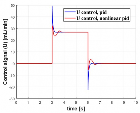
Figure 8. Control signal (U) at PID and nonlinear PID control method
It is imperative to acknowledge that the magnitude of the phase plane in isolation does not conclusively determine the effectiveness of a controller. An adeptly calibrated nonlinear PID controller, even with a more compact phase plane, is capable of providing effective control of the system. Conversely, a PID controller, despite possessing a larger phase plane, may fail to offer efficient control if not properly tuned. This observation underscores the complexity of control system design and the necessity of precision in controller tuning. Further, Figure 8 illustrates key concepts in pressure control, specifically focusing on overshoot and oscillation phenomena. In the context of respirator pressure control, overshoot refers to the magnitude by which the pressure surpasses the set or desired value before returning to the required level. Such overshoot can transpire when the inspiratory flow rate is excessively high or the expiratory flow rate is insufficiently low, leading to a temporary exceedance of the desired pressure level. In the realm of bellows pressure control, overshoot might occur when the internal pressure of the bellows surpasses the set pressure prior to being alleviated via a relief valve. Oscillation in pressure is characterized by the fluctuation of pressure around a set point or a desired level. Within respirator pressure control systems, oscillations can arise due to a variety of factors, including alterations in patient demand, changes in flow rate, or variations in airway resistance. These oscillations are pivotal in understanding the dynamic response of the system to external and internal changes, highlighting the importance of a controller's ability to mitigate such fluctuations while maintaining the desired pressure levels.
Clinical implications of oscillatory behavior in ventilation control systems are profound, particularly concerning patient comfort and safety. Oscillations in airway pressure, especially when frequent or intense, may contribute to patient discomfort and risk of ventilator-induced lung injury. This underscores the criticality of employing control systems that maintain smooth pressure profiles, a necessity that becomes even more pressing for vulnerable groups such as neonates or patients with pre-existing lung conditions. The selection of an appropriate control system is contingent upon the specific demands and limitations of the application at hand. Generally, nonlinear PID controllers exhibit greater efficacy in managing systems characterized by high nonlinearity and complexity. Conversely, traditional PID controllers are better suited to simpler, more linear systems. In cases where the controlled system displays complex, nonlinear dynamics, a finely tuned nonlinear PID controller is likely to outperform a standard PID controller. However, in scenarios involving more straightforward and linear dynamics, a well-calibrated PID controller may prove more effective. The robustness of a controller, particularly in medical settings, is of utmost importance. The study found that both PID and nonlinear PID controllers displayed certain vulnerabilities under specific conditions. For example, while the nonlinear PID controller showed heightened sensitivity to disturbances, it adeptly captured the nonlinearities intrinsic to the system dynamics. Nonetheless, the increased complexity of the nonlinear PID controller may introduce additional potential failure points, a consideration that must be carefully managed in practical applications. On the other hand, the PID controller, with its simpler and more established design, might fail to effectively manage certain complex dynamics, potentially leading to suboptimal outcomes for patients.
Effectiveness of a control system depends on the specific requirements and constraints of the application. The choice between PID and nonlinear PID controllers should be based on the system's complexity and the quality of tuning and implementation. Careful evaluation of both systems is essential to determine the most appropriate balance of performance, stability, and sensitivity to disturbances.
Additionally, this study acknowledges the potential relevance of other control strategies for ventilator systems, such as adaptive control, model predictive control, and fuzzy logic controllers. A comparative study including these methods would provide a more comprehensive view of the optimal control strategy for ventilators.
4.2 PID and nonlinear PID results
The PID and nonlinear PID controllers, as delineated in the previous section, have been employed to simulate the ventilator system. The effectiveness of the PID controller is assessed and compared with other recommended controllers to demonstrate the limits of control techniques. Ventilator unit parameters, outlined in Table 1, were utilized in this simulation. The controller configurations were adjusted using MATLAB's response optimization toolbox with the reference signal Pr. Table 2 presents the tuned settings of the controllers. Two distinct tests were conducted on the ventilator system:
·System testing under fixed parameters to simulate an ideal situation.
·Testing under ambiguous conditions to evaluate robustness.
4.2.1 PID control test
In the first test, the ventilator unit's settings were considered constants. The system parameters a1, b1, c1, d1, and d2 were derived using the parameters reported in Table 2.
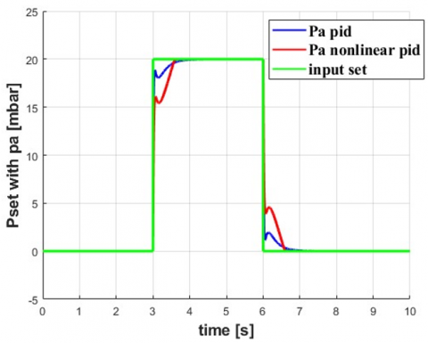
Figure 9. Comparison between Pa and Pset at PID and nonlinear PID controllers
Figure 9 depicts a comparison between Pa and Pset using PID and nonlinear PID controllers. The airway pressure command Pset is selected as follows:
$\begin{gathered}P_{\text {set }}=0 \mathrm{mbar}, \\ t=(0 \rightarrow 3 \text { and } 6 \rightarrow 10) \mathrm{s}, \\ P_{\text {set }}=20 \mathrm{mbar}, t=(3 \rightarrow 6) \mathrm{s}\end{gathered}$ (70)
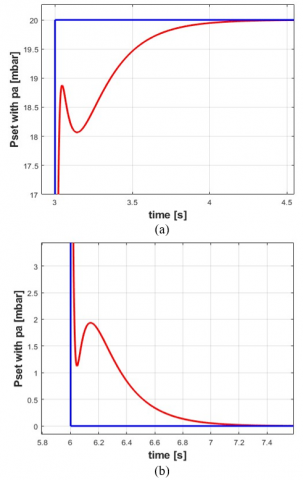
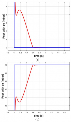
Figure 9 delineates the airway pressure tracking response utilizing a PID controller of integer order. Notably, the reference command undergoes abrupt changes at t=3s and 6s. For enhanced clarity, Figure 10 presents magnified views of specific instances from Figure 9, specifically at t=1s and 5s. Examination of Figure 10 reveals that the airway pressure tracking via the PID controller results in diminished oscillations at t=3s and 6s. The system experiences overshoots peaking at 18 mbar and 0.6 mbar during these respective time intervals. Moreover, these oscillations stabilize at approximately 3.9s and 6.9s when deploying an integer-order PID controller. This behavior is attributable to the integral gain K of the PID controller, which enhances the rise time but concurrently extends the response duration [24, 25]. Such a modulation culminates in a suboptimal tracking response for the ventilator system, characterized by a protracted rise time. It is pertinent to note that augmenting the integral gain of the PID controller might reduce the rise and settling times, but this adjustment risks inducing additional overshoots and oscillations.
Figure 10. Airway pressure Pa at PID control: (a) Enlargement of upper corner and (b) Enlargement of bottom corner
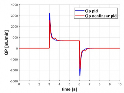
Figure 11. Flowrate (Qp) at PID and nonlinear PID control
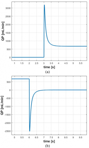
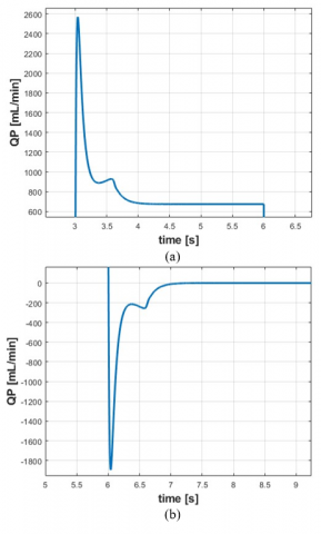
Figures 11 and 12 compare the response of patient flow rate Qp using the controllers. Figure 11 shows that the flow rate response is delayed with the PID controller. Figure 12 provides a clearer view of the patient flow rate response using the fractional order PID controller.
Figure 12. Enlargement shape of Qp at PID control: (a) Enlargement of upper corner (b) Enlargement of bottom corner
The peak recorded value of Qp with the PID controller is 3100 mL/min. The PID controller offers smoother patient airflow with enhanced rise time and fewer oscillations.
4.2.2 Nonlinear PID control test
In the second test, the ventilator unit's parameters were subjected to uncertainty, as delineated in Eqs. (71) and (72) [15].
$D_{p 1}=-0.01 a_1 * p_1+0.01 b_1 * 5 p_o$ (71)
$D_{P a}=-0.25 * c_1 * d_1+0.01 d_1 * p_o$ (72)
The reference airway pressure command Pset remained unchanged, as stated in Eq. (70), with disturbance terms introduced at t=3s. Figure 9 compares the airway pressure tracking response using the PID controller under these conditions. For enhanced visibility, Figure 13 provides an enlarged view of the airway pressure and its error response at t=3s. Results in Figure 13 indicate that, at t=3s, the PID controller records a peak overshoot of 4 mbar. Conversely, the PI controller exhibits a lagging response.
Figure 13. Enlargement shape of Pa at nonlinear PID control: (a) Enlargement of bottom corner (b) Enlargement of upper corner
The simulation and comparison of patient flow rate are portrayed in Figures 11 and 14. Figure 14 presents an enlarged view of Qp, focusing on the interval of uncertainty application at t=3s.
Upon the introduction of uncertainty terms at t=3s, the nonlinear PID controller exhibits a peak overshoot of approximately −1500 mL/min. Figures 10 and 12 demonstrate that the proposed PID controller ensures stable airflow to the patient, devoid of high-frequency oscillations. In contrast, Figures 13 and 14 reveal that the nonlinear PID controller induces some frequency oscillations. Moreover, the introduction of uncertainty terms leads to a delayed response in patient flow Qp, as observed in Figure 14.
This study's broader impacts and limitations must be recognized. First, the simulations rely on mathematical models, which, though robust, do not encompass all complexities of real-world clinical scenarios. Factors such as patient-specific lung mechanics, humidification effects, and equipment variability can significantly influence controller performance. Furthermore, long-term effects of utilizing a specific controller on patient outcomes remain unexplored in this study. Metrics such as patient comfort, lung tissue stress, or outcomes after extended ventilation periods need further investigation. This study serves as an initial exploration into the comparison of PID and nonlinear PID control for ventilators. Comprehensive clinical trials and in-depth studies are required to validate these findings and refine the control strategy further.
Figure 14. Enlargement shape of the Qp at nonlinear PID control: (a) Enlargement of upper corner; (b) Enlargement of bottom corner
In this study, the primary aim was to design a proficient control system for a ventilator unit, with a focus on optimizing blower model reduction techniques. This aim was driven by the urgent requirement to enhance the adaptability and efficiency of ventilator control systems, particularly in light of escalating medical challenges.
The research findings revealed that the airway pressure tracking exhibited significant oscillations when a nonlinear PID controller was utilized at t=3s and 6s. Furthermore, with a conventional PID controller, overshoots reached peak values of 18 mbar and 0.6 mbar at t=3s. Despite this, the nonlinear PID controller demonstrated superior performance compared to the conventional PID controller, particularly in terms of faster rise time, improved settling time, and reduced oscillations in airway pressure. It is noted that while overshoots peaked at 18 mbar and 0.6 mbar with the nonlinear PID controller at t=3s, the oscillations swiftly stabilized. However, it is crucial to recognize the limitations of this study. One such limitation is the computational intensity associated with the proposed fractional-order controller. While efforts have been made to mitigate this challenge, further optimization may be required for real-time implementation. Future investigations could focus on refining these computations and potentially incorporating new technologies to enhance efficiency. Additionally, conducting more extensive in-vivo testing could yield deeper insights into the practical efficacy of the system.
From a clinical perspective, the advantages of a responsive, accurate, and robust control system in a ventilator unit are paramount. In critical medical scenarios, particularly for patients with compromised respiratory functions, the capacity of the ventilator to swiftly and effectively adapt can be crucial for patient outcomes.
In conclusion, this study represents a significant contribution to the field of ventilator control systems, particularly in the nuanced management of blower dynamics. By integrating model reduction techniques and innovating the nonlinear PID approach, this study introduces a novel method that promises enhanced performance metrics. These findings not only advance the capabilities of ventilator design but also pave the way for future developments in this vital area of medical technology.
[1] Akoumianaki, E., Lyazidi, A., Rey, N., Matamis, D., Perez-Martinez, N., Giraud, R., Richard, J.C.M. (2013). Mechanical ventilation-induced reverse-triggered breaths: A frequently unrecognized form of neuromechanical coupling. Chest, 143(4): 927-938. https://doi.org/10.1378/chest.12-1817
[2] Borrello, M. (2018). Adaptive control of a proportional flow valve for critical care ventilators. In 2018 Annual American Control Conference (ACC), Milwaukee, WI, USA, pp. 104-109. https://doi.org/10.23919/ACC.2018.8431425
[3] Abolghasemi, V., Ferdowsi, S. (2015). EEG–fMRI: Dictionary learning for removal of ballistocardiogram artifact from EEG. Biomedical Signal Processing and Control, 18: 186-194. https://doi.org/10.1016/j.bspc.2015.01.001
[4] Li, Q., Li, D. (2017). Structure damage identification under ambient excitation based on wavelet packet analysis. In Journal of Physics: Conference Series, 842(1): 012023. https://doi.org/10.1088/1742-6596/842/1/012023
[5] Bisht, A., Srivastava, S., Purushothaman, G. (2020). A new 360 rotating type stimuli for improved SSVEP based brain computer interface. Biomedical Signal Processing and Control, 57: 101778. https://doi.org/10.1016/j.bspc.2019.101778
[6] Khakpour, E., Masoudi, R., Baghestan, K. (2019). Nonlinear PID control of tidal volume in volume-controlled mechanical ventilation using adaptive neuro-fuzzy inference system. Biomedical Signal Processing and Control, 52: 159-168. https://doi.org/10.1016/j.bspc.2019.03.019
[7] Korrapati, S., Yang, J.S. (2016). Adaptive inverse dynamics control for a two-compartment respiratory system. In 2016 IEEE International Conference on Consumer Electronics-Taiwan (ICCE-TW), Nantou, Taiwan, pp. 1-2. https://doi.org/10.1109/ICCE-TW.2016.7521037
[8] Li, H., Haddad, W.M. (2012). Model predictive control for a multicompartment respiratory system. IEEE Transactions on Control Systems Technology, 21(5): 1988-1995. https://doi.org/10.1109/TCST.2012.2210956
[9] Reinders, J., Verkade, R., Hunnekens, B., van de Wouw, N., Oomen, T. (2020). Improving mechanical ventilation for patient care through repetitive control. IFAC-PapersOnLine, 53(2): 1415-1420. https://doi.org/10.1016/j.ifacol.2020.12.1906
[10] Hunnekens, B., Kamps, S., Van De Wouw, N. (2018). Variable-gain control for respiratory systems. IEEE Transactions on Control Systems Technology, 28(1): 163-171. https://doi.org/10.1109/TCST.2018.2871002
[11] Alginahi, Y.M., Kabir, M.N., Mohamed, A.I. (2013). Optimization of high-crowd-density facilities based on discrete event simulation. Malaysian Journal of Computer Science, 26(4): 312-329.
[12] Uddin, M.J., Alginahi, Y., Bég, O.A., Kabir, M.N. (2016). Numerical solutions for gyrotactic bioconvection in nanofluid-saturated porous media with Stefan blowing and multiple slip effects. Computers & Mathematics with Applications, 72(10): 2562-2581. https://doi.org/10.1016/j.camwa.2016.09.018
[13] Shanan, D.S., Kadhim, S.K. (2023). Comparative analysis of airflow regulation in ventilator systems using various control strategies. Journal Européen des Systèmes Automatisés, 56(5): 811-821. https://doi.org/10.18280/jesa.560512
[14] Redmond, D.P., Kim, K.T., Morton, S.E., Howe, S.L., Chiew, Y.S., Chase, J.G. (2017). A variable resistance respiratory mechanics model. IFAC-PapersOnLine, 50(1): 6660-6665. https://doi.org/10.1016/j.ifacol.2017.08.1533
[15] Ullah, N., Mohammad, A.S. (2022). Cascaded robust control of mechanical ventilator using fractional order sliding mode control. Mathematical Biosciences and Engineering, 19(2): 1332-1354. https://doi.org/10.3934/mbe.2022061
[16] Mehedi, I.M., Shah, H.S., Al-Saggaf, U.M., Mansouri, R., Bettayeb, M. (2021). Fuzzy PID control for respiratory systems. Journal of Healthcare Engineering, 2021: 7118711. https://doi.org/10.1155/2021/7118711
[17] Borrello, M. (2005). Modeling and control of systems for critical care ventilation. In Proceedings of the 2005, American Control Conference, Portland, OR, USA, pp. 2166-2180. https://doi.org/10.1109/ACC.2005.1470291
[18] Katsuhiko, O. (2009). Modern control engineering. Editorial Félix Varela.
[19] Noaman, M.N., Gatea, A.S., Humaidi, A.J., Kadhim, S.K., Hasan, A.F. (2023). Optimal tuning of PID-controlled magnetic bearing system for tracking control of pump impeller in artificial heart. Journal Européen des Systèmes Automatisés, 56(1): 21-27. https://doi.org/10.18280/jesa.560103
[20] Humaidi, A.J., Oglah, A.A., Abbas, S.J., Ibraheem, I.K. (2019). Optimal augmented linear and nonlinear PD control design for parallel robot based on PSO tuner. International Review on Modelling and Simulations, 12(5): 281-291. https://doi.org/10.15866/iremos.v12i5.16298
[21] Rasheed, L.T., Yousif, N.Q., Al-Wais, S. (2023). Performance of the optimal nonlinear PID controller for position control of antenna azimuth position system. Mathematical Modelling of Engineering Problems, 10(1): 366-375. https://doi.org/10.18280/mmep.100143
[22] Najm, A.A., Azar, A.T., Ibraheem, I.K., Humaidi, A.J. (2021). A nonlinear PID controller design for 6-DOF unmanned aerial vehicles. In Unmanned Aerial Systems, pp. 315-343. https://doi.org/10.1016/B978-0-12-820276-0.00020-0
[23] Scheel, M., Berndt, A., Simanski, O. (2015). Iterative learning control: An example for mechanical ventilated patients. IFAC-PapersOnLine, 48(20): 523-527. https://doi.org/10.1016/j.ifacol.2015.10.194