Nihad Yaseen Abbas*![]() | Ahmad Jabbar Hussain Alshimmeri
| Ahmad Jabbar Hussain Alshimmeri![]()
© 2024 The authors. This article is published by IIETA and is licensed under the CC BY 4.0 license (http://creativecommons.org/licenses/by/4.0/).
OPEN ACCESS
This numerical study presented and analysed a new technic of castellated steel beam "Alternate Closed Opening Castellated Beam" applied only to double steel channel shapes connected back to back. ABAQUS/2019 program employed to create modelling and analysis for two groups of models with the same length and conditions of loading. The first group has three noncomposite beam models: the first reference model without castellated, the second model with normal castellated and the third model with new castellated, also the second group has three composite beam models: the first reference model without castellated, second model with normal castellated and the third model with the new castellated. According to the analysis results; For the first noncompsite group, ultimate load for the second and third models increased by 8.84% and 16.63%, respectively, compared to the reference model, with local buckling in the top flanges under concentrated loads and lateral-torsional buckling as the failure modes. For the second composite group, the ultimate load for the second and third models increased by 41.83% and 62.19%, respectively, compared to the first reference model, with the flexural mechanism as the main failure mode. This enhancement in the load-carrying capacities of the new Alternate Closed Opening Castellated Beams is due to the limit states mode of failures resulting from web holes.
castellated beam, noncomposite beam, composite beam, double steel channel, ultimate load, deflection, stiffness, ABAQUS software
Castellated steel beams are manufactured by enlarging standard rolled shapes to form a regular shape of holes in the web. Castellated steel beams were major used in 1910 by means of the Chicago Bridge and the Iron Works [1]. That kind was also proceeded by Boyer [2] in 1964 and subsequently in the United Kingdom [3]. Currently, the use of castellated steel beams has become more popular in the past two decades and is currently governed by design guidelines and fairly well-established practice rules. Although they are constantly reviewed to reflect the latest developments and results, castellated beams are simple to construct because of contemporary cutting and welding procedures. Buildings that use castellated beams benefit from the increased flexural rigidity of the members, acceptable means of material economy, lighter beams, and conveyance of services through the web holes [4]. In 2014, Jamadar and Kumbhar studied castellated steel beams' flexural behavior using finite element analysis (Abaqus). I beam (IS MB 600) with hexagonal holes. The flexural behavior of the origin and castellated beams for combined axial bending stresses and deflection under uniformly distributed load and simply supported conditions were studied. Modelling of original and castellated beams is performed by ABAQUS software using solid elements. It was found that it is important to check the local failure of the castellated beam because of the lack of shear transfer area; therefore, it is necessary to optimize between the size and shape of holes and finite element analysis by using ABAQUS software gave good agreement with the results calculated by Indian standards method analysis [5]. Using castellated beams has significant design and construction advantages. The expanded section modulus (Sx) and depth-to-weight ratio for open web beams and the enlarged strong axis moment of inertia (Ix) are both substantial. In comparison to the original beams, these enhancements lead to an extended span that designers can use for wide-span options, a stiffer and more durable standard section, and a decrease in deflection. Beams produced by the castellation method were 50% higher than the original beam, increased moment capacity by up to 40% without the use of steel, and increased load capacity by making the beams lighter [6]. In Khaleel and AL-Shamaa [7]’s study, five specimens of 2C-shapes beam with different shapes and numbers of openings web, and this study showed that bearing strength decreases when the web holes are few. As the number of web holes increased to a specific limit, the bearing strength continued to rise, and if openings exceeded a specific limit, the bearing force decreased; the rate of increase in the bearing force was found to be between 17.7% to 40.0%. By tracing the literature review, no practical or theoretical studies are related to studying the behavior of composite concrete asymmetrical castellated steel (double channel shape connected back to back by bolts) beams or closed openings of castellated steel beams that are present in this study and found in the literature.
Current theoretical research aims to present a new technique of the castellated steel beam with a proposal to name it Alternate Closed Opening Castellated Beam (CcB), compare it with the ordinary technique of the castellated steel beam (CB), and study the enhancements applied to its original solid-steel beam, with the noncomposite and composite beams using the same property of the material used and conditions of loading.
2.1 Fabricating of CcB
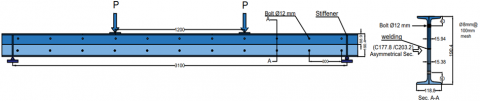
The CcB is applied only to a double steel channel shape connected back-to-back. The fabricating process is the same as in the CB, which begins by taking each channel and using "CNC" (computer numerical control) to cut a limiting zigzag line along the channel's web as two asymmetrical halves. Next, both parts are separated by sides to make four parts from two channels. Next, it was reconnected by welding on web posts for two selected parts to create two castellated channels with new opening patterns; finally, two castellated channels were connected back to back by bolts to produce the unique CcB with deference to CB in omitted opening show; also, there is increased in the depth of about 1.5 times compared with the original channels before the castellated process, as shown in Figure 1, while Figures 2, 3 illustrated the CcB and CB [3, 6] parameters, respectively.
2.2 Examined models specifications and material characteristics
They are evaluating the effects of the castellation process on the asymmetrical 2C-shapes, the upper part is 2C7×12.25, and the lower part is 2C8×13.75 [8], using the CcB and with the CB on the ultimate load and deflection and comparing the results with the original solid beam (2C-shapes). Two groups are presented: the first noncomposite beam with three models and the second composite beam with three models too; also, all models have the same length and boundary condition of supported reactions with two concentrated static loads. Table 1 and Figures 4, 5 illustrate all the measurements.
Figure 1. The fabricating process of the CcB
Figure 2. The CcB parameter
Figure 3. The CB beam parameters
Table 1. Dimension details of models
|
Group No. |
Model No. |
dg mm |
e mm |
dttop mm |
dtbot mm |
S mm |
ho mm |
Beff. mm |
|
1 |
1 |
190.4 |
---- |
----- |
----- |
----- |
----- |
----- |
|
2 |
290.4 |
100 |
38.9 |
51.5 |
400 |
200 |
----- |
|
|
3 |
290.4 |
100 |
38.9 |
51.5 |
300 |
200 |
----- |
|
|
2 |
4 |
260.4 |
---- |
----- |
----- |
---- |
----- |
450 |
|
5 |
360.4 |
100 |
38.9 |
51.5 |
400 |
200 |
450 |
|
|
6 |
360.4 |
100 |
38.9 |
51.5 |
300 |
200 |
450 |
Figure 4. Models of group (1) with section details, all dimensions in mm
Figure 5. Models of a group (2) with section details, all dimensions in mm
Mechanical properties of steel components and slab concrete are illustrated in Tables 2, 3 adopted in this theoretical study.
The hex bolts and nuts' mechanical properties have a diameter of 12mm, fy=640MPa and fu=800MPa (BS 3692 Grade 8.8) [9].
Table 2. Mechanical characteristics of the steel
|
Sample |
Thickness (mm) |
fy (Mpa) |
fu (Mpa) |
|
C7×12.25 (Web) (flange) |
7.9 9.2 |
381 340 |
574 585 |
|
C7×13.75 (Web) (flange) |
7.9 9.9 |
390 396 |
621 554 |
|
Stiffeners |
12 |
390 |
621 |
|
Shear connectors Steel channel |
3 |
456 |
615 |
|
Slab Reinforcement |
(8mm) diameter |
420 |
623.5 |
|
Rebar lacing |
(6mm) diameter |
430 |
640 |
Table 3. Mechanical properties of slab concrete
|
Model No. |
f'c (Mpa) |
fcu (Mpa) |
f'ct (Mpa) |
fr (Mpa) |
Ec (Mpa) |
|
4,5,6 |
26.64 |
33.3 |
3.11 |
3.31 |
23991 |
3.1 Finite element simulation
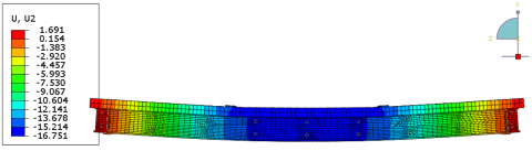
Using the finite element program ABAQUS/2019 [10], the maximum deflection at mid-span and the ultimate load for the tested six models exposed to a two-point load under simply support conditions were computed numerically. A solid element that is a continuum 3D 8-node hexahedron (C3D8R) were used for model castellated steel section, concrete, bolts, stiffeners and steel plate under loading. For reinforcement rebars, the line elements of type (T3D2) were used, while quadrilateral elements of type (S4R) using for the shear connector. For modelling typical three-dimensional solid structures, these elements proved sufficient [11]. The approximate global mesh size of 30mm was chosen as the mesh size. Both material geometry and nonlinearity were taken into account by the finite element models. Figures 6, 7 and Figures 8, 9 display the stresses and displacement for noncomposite and composite beams, respectively.
Figure 6. Stress results for group (1) models
Figure 7. Displacement results for group (1) models
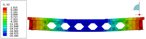
Figure 8. Stress results for group (2) models
Figure 9. Displacement results for group (2) models
3.1.1 Ultimate load, deflection and mode failure
The deflection results at mid-span from the start loading up to the ultimate load for all studied models are illustrated in Figures 10 and 11 for groups 1 and 2, respectively. The maximum load capacity for group (1) and for group (2) are shown in Figures 12, 13, respectively; also, Table 4 includes the comparisons in ultimate load with the reference model No. 1 in group (1) and model No. 4 in group (2) and the failure modes for each model.
The Results indicate that the load-carrying capacities for models (2, 3) in group (1) of noncomposite concrete asymmetrical castellated steel increased by 8.84% and 16.63%, respectively, compared to the origin reference model No.1 in the group (1), with F.L.B (top flange) under loads and L.T.B as the mode failure. Also, the load-carrying capacities for models (5, 6) in group (2) of the composite concrete asymmetrical castellated steel increased by 41.83% and 62.19%, respectively, compared to the origin reference model No.4 in the group (2) with the Flexural mechanism as the mode failure. This enhancement in the load-carrying capacities is due to the effect of increasing the beams' section depth with opening castellated for CB, In the other case in CcB, in addition to increasing depth, there are closed in the web openings, which leads to a decrease in the effect the limit states mode of failures due to the existence of web holes, as the vierendeel bending, flexural failure mechanism, rupture of welded joints, compression web post-buckling, and Lateral torsional buckling [3], Thus, the bearing of the CcB is greater than the CB.
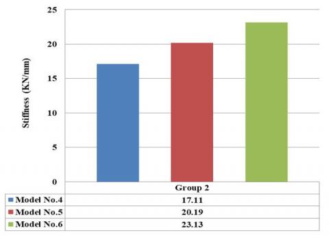
3.1.2 Stiffness
Stiffness [12, 13] is the amount of force required to cause a unit to deflect. It is calculated using values for ultimate load and deflection from finite element analysis. According to the results, the CcB stiffness is larger than in the CB. Stiffness results are illustrated in Table 5 and Figures 14, 15 for group 1 and group 2, respectively.
Figure 10. Curves of load-deflection for Group 1
Figure 11. Curves of load-deflection for Group 2
Figure 12. Ultimate load for Group 1
Figure 13. Ultimate load for Group 2
Figure 14. Stiffness values for Group 1
Figure 15. Stiffness values for Group 2
Table 4. Ultiate load, deflection and failure modes for all models
|
Group No. |
Model No. |
Pult. (kN) |
Δ Ult. mm |
$\frac{\text { P ult. }- \text { P ref. }}{\text { P ref. }} \times 100 \%$ |
Failure Mode |
|
1 |
1 |
221.51 |
34.60 |
---- |
F.L.B and L.T.B |
|
2 |
241.11 |
15.76 |
8.84 |
F.L.B and L.T.B |
|
|
3 |
258.35 |
15.10 |
16.63 |
F.L.B and L.T.B |
|
|
2 |
4 |
286.60 |
16.75 |
--- |
Flexural Mechanism |
|
5 |
406.50 |
20.10 |
41.83 |
Flexural Mechanism |
|
|
6 |
464.85 |
20.09 |
62.19 |
Flexural Mechanism |
Table 5. Stiffness of the examined models
|
Group No. |
Model No. |
Pult. (kN) |
Δ Ult. (mm) |
Stiffness= $\frac{\text { Pult }}{\Delta \text { Ult. }}$ (kN/mm) |
Increase in Stiffness % |
|
1
|
1 |
221.51 |
34.60 |
6.40 |
---- |
|
2 |
241.11 |
15.76 |
15.29 |
138.9 |
|
|
3 |
258.35 |
15.10 |
17.10 |
167.1 |
|
|
2
|
4 |
286.6 |
26.75 |
17.11 |
---- |
|
5 |
406.5 |
20.10 |
20.22 |
18.17 |
|
|
5 |
464.85 |
20.09 |
23.14 |
35.23 |
Based on the ABAQUS program's numerical results gotten in this study, the following conclusions are made:
(1) The ultimate load for noncomposite group models: CcB increased by about 16.63%, and CB increased by about 8.84% compared to the original solid steel reference model in group 1. While the ultimate load in composite group models: CcB increased by about 62.19%, and CB increased by about 41.83% compared to the original solid steel reference model in group 2.
(2) The stiffness values of CcB are larger than CB and the original solid steel reference model in non-composite and composite group models.
(3) In noncomposite castellated beams, the F.L.B and L.T.B are the failure modes control, while in composite castellated beams, the flexural mechanism is the failure modes control.
(4) This new technique of castellated steel beams "CcB" is adequately applied for a double steel channel shape connected back to back due to the limit states mode of failures resulting from web holes.
The paper was funded by The University of Baghdad/Iraq, and the Civil Engineering Department provided assistance and support.
|
AISC |
American Institute of Steel Construction |
|
ASTM |
American Society for Testing Materials |
|
CB |
Castellated Beam |
|
CcB |
Alternate Closed Opening Castellated Beam |
|
Ix |
Moment of Inertia about x- axis |
|
No. |
Number |
|
Sx |
Elastic Section Modulus about x-axis |
|
Zx |
Plastic Section Modulus about x-axis |
|
Greek Symbols |
|
|
$\Delta$ ult. |
deflection at ultimate load |
|
$\theta$ |
angle of hexagonal cut, in degrees |
|
Subscripts |
|
|
Beff |
effective width of the deck slab |
|
dg |
depth of the expanded beam |
|
dtbot |
depth of the bottom tee |
|
dttop |
depth of top tee |
|
e |
minimum width between web post |
|
E |
Modulus of elasticity |
|
Ec |
concrete modules of elasticity |
|
$f^{\prime}{ }_{\mathrm{c}}$ |
cylinder compressive strength |
|
$f^{\prime}{ }_{\mathrm{ct}}$ |
concrete splitting tensile strength |
|
$f_{\mathrm{cu}}$ |
cube compressive strength |
|
$f_{\mathrm{r}}$ |
modulus of rupture and |
|
$f y$ |
yield strength of steel |
|
$f u$ |
ultimate stress |
|
F.L.B |
Flange local buckling |
|
ho |
height of holes of castellated |
|
L.T.B |
lateral torsional buckling |
|
Pref. |
ultimate load for references specimens |
|
Pult. |
ultimate load |
|
S |
distance between the centre of holes |
|
ts |
deck slab thickness |
[1] Das, P.K. (1984). Handbook for the Design of Castellated Beams. Taylor & Francis, vol. 10.
[2] Boyer, J.P. (1964). Castellated beams-new developments. AISC Engineering Journal, 1(3): 104.
[3] Knowles, P.R. (1991). Castellated beams. Proceedings of the Institution of Civil Engineers, 90(3): 521-536. https://doi.org/10.1680/iicep.1991.14728
[4] Zirakian, T., Showkati, H. (2006). Distortional buckling of castellated beams. Journal of Constructional Steel Research, 62(9): 863-871. https://doi.org/10.1016/j.jcsr.2006.01.004
[5] Jamadar, A.M., Kumbhar, P.D. (2014). Finite element analysis of castellated beam: A review. International Journal of Innovative Research in Advanced Engineering (IJIRAE), 1(9): 125-129.
[6] Fares, S., Coulson, J., Dinehart, D. (2016). Castellated and cellular beam design. American Institute of Steel Construction.
[7] Khaleel, A.I., Al-Shamaa, M.F. (2021). Experimental investigation on the structural behavior of double channel castellated steel beams. In E3S Web of Conferences. EDP Sciences, vol. 318. https://doi.org/10.1051/e3sconf/202131803009
[8] American Institute of Steel Construction. (2005). Steel construction manual. American Institute of Steel Construction.
[9] Standard, B. (2000). G2000-Structural use of steelwork in Building. Part 1: Code of Practice for Design Rolled and Welded Sections.
[10] ABAQUS/CAE user's manual 2019. http://130.149.89.49:2080/v6.11/pdf_books/CAE.pdf
[11] ABAQUS analysis user guide 2019. http://130.149.89.49:2080/v6.14/books/usb/default.htm.
[12] Ellobode, E. (2014). Finite element analysis and design of steel-concrete composite bridges. Tanta University, Egypt: Elsevier Inc.
[13] Ahmad, S., Masri, A., Abou Saleh, Z. (2018). Analytical and experimental investigation on the flexural behavior of partially encased composite beams. Alexandria Engineering Journal, 57(3): 1693-1712. https://doi.org/10.1016/j.aej.2017.03.035