Hala Al-Hashmi*![]() | Abdullah Al-Hussein
| Abdullah Al-Hussein![]() | Ihsan Al-Abboodi
| Ihsan Al-Abboodi![]()
© 2023 IIETA. This article is published by IIETA and is licensed under the CC BY 4.0 license (http://creativecommons.org/licenses/by/4.0/).
OPEN ACCESS
The transitional zone between a bridge and its adjoining roadway, known as the bridge approach, frequently experiences differential settlement. This study employs the three-dimensional finite element software SAP2000 V22 to rigorously examine the performance of bridge approach slabs under vehicular loads, with a particular focus on the interaction between the slabs and embankment settlement. Bridge approach slabs and soil are modelled using shell and solid elements, respectively, with the soil characterized by the Drucker-Prager material model. A comprehensive investigation is undertaken to evaluate the effects of various soil and slab parameters on the system's performance, including slab thickness, slab length, approach slab restriction, fill material thickness, and soil's elastic modulus. Furthermore, a sensitivity analysis considering different boundary conditions is also conducted. The outcomes of the analysis include predicted slab deformations and bending moments under design traffic loads. Notably, a correlation is found between increased settlement and approach slab length at the slab's unrestricted boundary, particularly for soils of lower stiffness. The results also suggest that enhancing the compacted fill material thickness and the soil's elastic modulus can reduce slab deflection. The boundary condition and thickness of the slab are identified as key determinants of settlement values. These findings offer valuable insights for engineering professionals aiming to optimize bridge approach slab design, thereby boosting structural integrity and durability.
approach slab, bridge, soil-structure interaction, SAP2000, settlement
The bridge approach, a critical facet of road-bridge structures, enables an effortless transition between the roadway pavement and the bridge structure itself. However, settlement at bridge approaches presents a significant challenge to these systems, potentially leading to the formation of bumps at bridge ends, which can cause accidents and demand high maintenance costs [1].
Various factors can trigger excessive settlement of the approach slab, including inadequate drainage, settlement of the backfill, and consolidation of the naturally occurring soils [2-5]. To address this issue, several techniques have been proposed by researchers, with a majority grounded in the principles of soil improvement. Among these, the implementation of a concrete slab is recognized as one of the most effective strategies for mitigating settlement in this zone.
Numerous studies have been conducted to inspect the efficacy of approach slabs in this regard. Owing to the complexity inherent in this zone, these studies predominantly employ two or three-dimensional finite element analysis. For instance, Cai et al. [6] utilized three-dimensional finite element analysis via ANSYS software, considering the interaction between the soil and the bridge approach slab during embankment soil settlement. Their findings illustrated the utility of finite element procedures in designing approach slabs for specified embankment settlements. Furthermore, they undertook parametric studies to develop a straightforward design procedure, with the intention of bypassing the need for complex finite element analysis in routine designs.
Similarly, Khodair and Nassif [7] leveraged the finite element software ABAQUS 2D to simulate the cracking behavior of bridge approach and transition slabs, accounting for various types of materials and boundaries. Their results suggested that a substantial increase in the approach slab's cracking load-carrying capacity can be achieved by increasing the slab thickness. Conversely, they also noted that elevated soil settlement adversely affects its cracking load-bearing capacity.
Geotechnical and structural elements significantly impact the performance of the approach slab. In this context, Thiagarajan et al. [8] employed a 3D finite element computer program, SAP 2000, to simulate the approach slab, examining its behavior under varying embankment settlements. The study took into account the interaction between the bridge approach and the soil, utilizing the beam-on-elastic-foundation concept. The objective was to devise a cost-effective approach slab. A comprehensive parametric study was carried out to ascertain the effects of slab thickness, slab length variations, slab end restrictions, and sand loss at support conditions. The study presented two solutions: new construction designs using cast-in-place, pre-cast pre-stressed slab designs for new constructions, and substitute approach slabs.
Similarly, Rajek [9] investigated the performance of the approach slab under different conditions, using a parametric analysis with 2D finite element analysis via the ABAQUS program. The study used the Mohr-Coulomb simulation to represent soil layers, concluding that soil and concrete stiffness significantly influenced approach slab performance.
Zhang et al. [10] employed ANSYS software to create a 3D finite element model, examining the impact of settlement on bump formation. The study identified several parameters to mitigate settlement in the bridge approach slab, concluding that increased slab thickness and soil modulus of elasticity reduced the slab's settlement.
The issue of bridge approach settlement was also addressed in other studies [11, 12] through a field survey and comparison with results from finite element analysis using SAP2000 software. These models represented the system as a beam on an elastic foundation, using Winkler's theory. Chen and Fan [13] developed a mathematical model for the bridge approach using the same theory, investigating the effect of soil washout and settlement on the performance of the approach system. Their results underscored the slab's deformation, bending moment, soil pressure, shear force, and the formation of voids beneath the slab. They found that even minor embankment settlement had a significant impact on the slab's moment demand.
Chee [14] explored the influence of skew and wing walls on the approach slab using SAP2000's linear elastic layered shell elements. The study compared field survey results with the numerical model. Al-Abboodi et al. [15] used 3D dynamic analysis to study the approach slab system, utilizing the Plaxis 3D software with the Mohr-Coulomb model. They considered several soil, slab, and vehicle parameters to examine slab behavior. A comparison between dynamic and static methods revealed that a load factor of 1.37 was suitable for incorporating dynamic effects into static analyses.
Previous numerical studies have largely approached the issue through a two-dimensional lens, simulating soil conditions as an elastic subgrade with the elastic modulus (k). In contrast, the present study employs a 3D finite element model of the bridge approach system using SAP2000. The slab is depicted using shell elements, while solid elements represent the soil.
The study assesses vehicle loads in accordance with the AASHTO LRFD Bridge Design Specifications 2007 (3.6.1.2 Vehicular Live Load) [1], identifying the type of vehicle load that precipitates the most severe load. Additionally, the analysis contemplates various parametric studies to scrutinize the impact of these parameters on the performance of the approach.
Hence, the purpose of this study is twofold: to analyze the behavior of the bridge approach system under traffic loads and to comprehend the interaction between approach slabs and embankment settlement. This investigation could augment our understanding of settlement behavior, support configuration, subgrade effects, fill thickness, and soil improvement techniques in bridge approach systems. This enhanced knowledge could then inform the development of improved design guidelines.
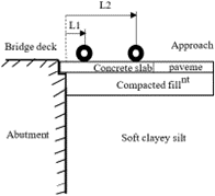
The geometric model of the bridge approach utilized in this study encompasses the following elements: pavement, approach slab, abutment, soils, and vehicle load. The components of the model under consideration are displayed in Figure 1.
Figure 1. The geometry of the standard case
A 3D finite element simulation was developed using the SAP2000 software, a versatile application used for structural analysis and design. This tool is employed in modeling and analyzing a diverse range of structures, including but not limited to bridges, buildings, and towers. Its robust capabilities allow users to craft intricate structural models that can be thoroughly examined under various loading conditions. It is also used to model soil-structure interaction, a crucial aspect in the design of bridges.
The analytical model used in this study comprises a slab supported by soil layers. The standard case approach slab measures 8 m in length, 0.3 m in thickness, and spans 7.3 m across two lanes. A pinned connection was utilized to connect the approach slab and the abutment. On the other hand, the other edge of the slab was supported by either the soil or a sleeper slab. Shell elements were used to simulate both the slab and the pavement.
The layers beneath the approach slab consisted of a combination of the embankment and soft clay soil. The properties of the concrete slab and pavement, detailed in Table 1, were used in the simulation. Additionally, the Drucker-Prager model was employed to define the properties of the embankment soil and the subgrade soil, as outlined in Table 1.
The accuracy of the present model was verified by comparing it with analytical results obtained by Chee [14], who used a beam on an elastic foundation. The comparison revealed a minor discrepancy in the settlement values obtained using the current methodology. However, the trend of moment and settlement results, as well as the worst vehicle load locations, were found to be largely consistent.
Table 1. Material properties
|
Layers |
Thickness (mm) |
Elastic Modulus (MPa) |
Unit Weight (kN/m3) |
Poisson Ratio |
Friction Angle (o) |
Dilation Angle (o) |
Cohesion (kPa) |
|
Concrete slab |
300 |
26000 |
24 |
0.15 |
- |
- |
- |
|
Pavement |
150 |
1500 |
24 |
0.30 |
- |
- |
- |
|
Compacted fill |
600 |
50 |
18.80 |
0.30 |
0 |
0 |
45 |
|
Soft clayey silt |
- |
13 |
18.30 |
0.30 |
0 |
0 |
17 |
3.1 Load combination and load location
This investigation presents a comparison of vehicular loads with the aim of identifying the critical position of vehicles passing over the approach. The critical position is characterized by the maximum induced bending moment and deflection in the slab. The analysis assesses various locations along the slab, scrutinizing the effects of the wheels on the maximum moment and maximum deflection. To facilitate this analysis, a simply supported slab with no soil underneath was considered.
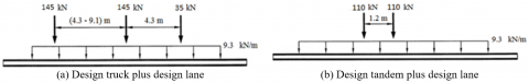
The analysis validates the design of both the tandem load and the truckload, while also taking into account the lane load in conjunction with these loads. Figure 2 illustrates the AASHTO LRFD HL-93 Model that is employed in this investigation.
Figure 2. The AASHTO HL93 design load
The load combinations that have been taken into account are as follows:
• Combinations of strength loads:
1.25 Dead load+1.75 Truck-load+1.75 Lane load
1.25 Dead load+1.75 Tandem load+1.75 Lane load
• Combinations of service load
Dead load+Truck-load+Lane load
Dead load+Tandem load+Lane load
Figure 3. Bending moment and deflection of bridge approach
Furthermore, the dynamic allowance, as outlined by the AASHTO guidelines [1], was considered to augment the static load of the wheel, accounting for the impact of the wheel load caused by vehicular movement. As per Figure 3(a), the deformation behavior of the approach slab revealed that the maximum deflection was observed in the tandem load case, which marked a (7%) increase compared to the truck load case. Likewise, the maximum bending moment was found to be amplified during the application of tandem loading, as depicted in Figure 3(b), relative to a truck load. The percentage increase in the maximum bending moment was approximately (14%). As a result, this study employed the tandem loading methodology.
3.2 Soil boundary condition
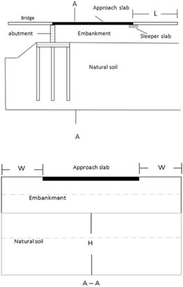
Figure 4. A model of the bridge-approach slab
Theoretically, the soil beneath the approach span is considered to be semi-infinite. A sensitivity analysis was carried out to ascertain the optimal dimensions of the model boundaries. The model boundaries were evaluated by varying the length of one boundary while keeping the other two boundaries constant. This study scrutinized three cases, denoted as W, L, and H, as illustrated in Figure 4. The decision to adopt a specific soil boundary location hinge on the deflection result of the approach slab.
In all instances, a pair of tandem loads was applied across two lanes, in addition to the self-weight of the slab. The three cases that were investigated are as follows:
L was systematically varied in the sequence of 2, 4, 6, 8, 10, 12, 14, 16, 18, and 20 m, while H and W were kept constant at 10 and 7.3 m, respectively. As per the calculated results shown in Figure 5, the optimal value of L for the longitudinal boundary condition of the soil is 4 m.
Figure 5. L versus settlement
The selection of this value is premised on the observation that when L exceeds 4 m, its influence on the settlement results is negligible.
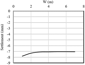
The value of W was altered in the sequence of 1, 2, 3, 4, 5, 6, and 7 m, while keeping the other dimensions constant at L=4 m and H=10 m. As depicted in Figure 6, the computed results clearly indicate that 3 m is the suitable value of W for the lateral soil boundary condition. The rationale for choosing this specific value is based on the observation that when W exceeds 3 m, its impact on the deflection results is immaterial.
Figure 6. W versus settlement
The study experimented with a range of values for H, including 5 m, 10 m, 20 m, 30 m, 40 m, 50 m, and 60 m., while keeping W fixed at 2 m and L constant at 4 m. The results, as shown in Figure 7, suggest that a value of 30 m for H would be suitable for the vertical soil boundary conditions. This is based on the observation that when H surpasses 30 m, its influence on settlement diminishes, although it still has a slight effect.
Figure 7. H versus settlement
Drawing from the analysis of the aforementioned three cases, the boundary conditions for the soil were established as follows: W=3 m, L=4 m, and H=30 m.
3.3 Parametric study
This study evaluated multiple parameters, including the impact of approach slab restriction, a comparison between the standard case and the case without a slab, slab length, slab thickness, subgrade elastic modulus, and compacted fill thickness. The parameters scrutinized in this investigation are the key factors thought to dictate the performance of the bridge approach slabs. Table 2 outlines the parameters and their corresponding variations for the parametric investigation.
Table 2. Parametric study
|
Parameter |
Range |
Notes |
|
Slab restriction |
Pin-free ends Pin-roller end |
Slab with standard case properties |
|
Approach type |
Concrete slab Pavement |
150 mm thickness for both cases |
|
Slab length |
6 to 18 m |
Variable |
|
Slab thickness |
200 to 400 mm |
Variable |
|
Subgrade elastic modulus |
15 to 35 MPa |
Variable |
|
Thickness of compacted fill |
300 to 1200 mm |
Variable |
3.3.1 Effect of slab end restriction
Two distinct cases were employed to explore the impact of the approach slab's restriction at its pavement end on the slab's behavior. An investigation was conducted on a pin-roller end in addition to the typical case of pin-free end support. A pinned support was assumed at the junction of the approach slab and the abutment. The current study adopted the roller support mechanism as a substitute for the sleeper slab to streamline the model simulation technique. This choice was made on the basis that the sleeper slab structure can yield or settle under normal service conditions. The analysis disregards the weight of the sleeper slab owing to its placement beneath the support system of the approach slab [16]. Moreover, the support of the soil was deemed to be consistently extended beneath the length of the slab's span. The analysis results outlined in Table 3 reveal that the installation of a pin-roller joint led to a reduction of approximately 45% in maximum deflection when compared to the pin-free end. On the other hand, due to the additional constraint of the slab, the maximum bending moment for the pin-roller end surpassed that computed in the standard (no sleeper slab) case by 4%.
Table 3. Values of settlement and bending moment
|
Case Name |
Max. Settlement (mm) |
Max. Bending Moment (kN.m) |
|
Pin-free-end support (standard case) |
-9.70 |
134.53 |
|
Pin-roller end support |
-5.28 |
140.55 |
The location of the maximum moment is contingent on the position of the wheel during movements in both cases. As expected, the slab's response was more pronounced when the axle loads were uniformly dispersed over the contact tire area, approximately at the midpoint of its length, in the adverse pinned-roller end situation.
3.3.2 Settlement in the standard case and case of no slab
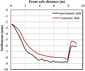
This study seeks to contrast the performance of the flexible pavement approach and the concrete approach slab. The results gleaned from Figure 8 suggest that the settlement of the pavement road varies along the approach, whereas the settlement of the concrete approach slab remains relatively steady. The noted variability can be attributed to the flexible nature of the pavement layers, in contrast to the rigid behavior of the concrete approach slab due to the material's high stiffness. Moreover, the findings indicate that, under equivalent load conditions and thickness, the settlement of the pavement approach is higher in comparison to the concrete approach slabs.
Figure 8. Settlement in the standard case versus settlement in the case of no slab
3.3.3 Effect of length of slab
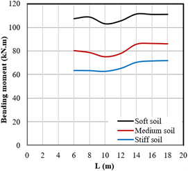
One of the primary questions in any bridge approach design is the length that the approach slab should be. The answer to this question depends on the available project budget, soil conditions, and boundary conditions. In the current study, the effect of slab length was examined using three different soil types (soft, medium, and stiff). The slab thickness was set to be constant at 0.30 m for all cases. Figure 9 reveals that an increase in the length of the approach slab results in an increase in the settlement at the free boundary of the approach slab. The calculated settlement is a function of soil stiffness. Soft compressible soil exhibits more settlement compared to medium and stiff soil. For soils that are medium or stiff, it was observed that the settlement at the free end remained reasonably constant, irrespective of the slab length. Conversely, in the case of soft soil, the settlement increases in proportion to the length of the slab. Furthermore, as observed from Figure 10, the maximum bending moment in the approach slab for compressible soils increases with the slab length.
Figure 9. Effect of approach slab length (L) on total settlement
Figure 10. Effect of approach slab length (L) on bending moment
The calculated maximum moment shows an increase in the case of soft soil compared to soils of medium or stiff consistency having similar lengths. The maximum slab bending moment remained constant when the length of the slab exceeded 14 m for all types of soils.
3.3.4 Effect of slab thickness
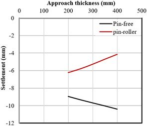
A parametric study was conducted to examine the effect of slab thickness on the response of the approach slab. The slab length was kept at 8 m and soft soil was utilized for the analysis. Two cases of end support were considered, namely, the pin-free end and the pin-roller end. Figure 11 demonstrates a clear relationship between the thickness of the approach slab and the settlement calculated at its free end. In the case of the free boundary, it can be observed that increasing the thickness of the approach slab increases the total settlement at the free boundary. This response can be attributed to the increased weight of the approach slab and the corresponding rigidity between the slab and the soil. On the other hand, the analysis results for the pin-roller end slab, as shown in Figure 11, indicate that increasing the thickness of the approach slab resulted in a significant decrease in the settlement.
Figure 11. Effect of approach slab thickness on settlement
In this case of end support, it's apparent that augmenting the slab thickness can lead to an increase in the load imposed on the soil. Interestingly, the lion's share of this additional weight is borne by the bridge abutments and the sleeper slab, rather than being directly transferred to the soil. The construction of a pin-free end slab results in the dispersion of this extra weight along the length of the slab, leading to amplified loads on the soil beneath. Consequently, despite the incremental enhancement in the flexural rigidity of the slab, the settlement escalates in scenarios where one end of the slab is unrestrained.
3.3.5 Effect of subgrade elastic modulus
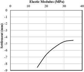
The stiffness of the natural soil is a critical determinant controlling slab settlement, especially when considering shallow fill depths. This study probes how the response of the approach slab (with a pin-free end support) is influenced by the natural stiffness of the soil. Different subgrade elastic modulus values, ranging from 15 to 35 MPa, were factored into the analysis. As illustrated in Figure 12, the findings reveal an inverse correlation between the elastic soil modulus and the settlement of the bridge approach slab. With an increase in the elastic soil modulus, the settlement decreases. For example, at an elastic soil modulus of 15 MPa, the settlement of the bridge approach slab was recorded at 8.56 mm. However, when the elastic soil modulus rose to 35 MPa, the settlement diminished to 4.50 mm.
The observed relationship can be attributed to the role of soil stiffness in the load-bearing capacity of the bridge approach slab. Higher values of elastic soil modulus signify greater soil stiffness, which bolsters the slab's capacity to resist deformation and settlement under imposed loads. As a result, with an ascending elastic soil modulus, lower settlement values are observed; additionally, a deceleration in the rate of increase is discernible at elevated values of the elastic modulus.
Figure 12. Effect of subgrade elastic modulus
3.3.6 Effect of the thickness of compacted fill
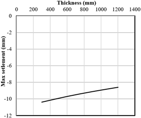
A comparative analysis was conducted to explore the effects of variations in the thickness of the compacted fill on the behavior of the approach slab, specifically with respect to its pin-free end support. Maximum values of deflections were cataloged for a range of compacted fill thicknesses, spanning from 300 mm to 1200 mm. The results, as depicted in Figure 13, indicate an inverse correlation between the thickness of the compacted fill and the slab's deflection. Essentially, an increase in the thickness of the compacted fill corresponds to a decrease in the slab deflection.
Figure 13. Effect of the thickness of compacted fill
Ultimately, one of the principal constraints in predicting the settlement of the approach slab is the factor of time. Investigations have revealed that this issue is time-dependent due to a variety of geotechnical and structural impacts. These include factors such as poor drainage, loss of lateral soil support in sloped approaches, consolidation of clay layers, and unanticipated heavy vehicular loads.
The present study conducted an exhaustive three-dimensional finite element analysis to scrutinize the response of bridge approach slabs when subjected to vehicular loads under a variety of soil and boundary conditions. Instead of using the widely accepted spring concept with SAP 2000 software, this study opted for testing real soil profiles. Evaluating different soil and structural elements within this problem zone could offer substantial economic benefits for future maintenance. The performance of the approach slab was evaluated in terms of deflection and bending moment. The analysis results led to the following conclusions:
Based on these conclusions, it is strongly recommended for both geotechnical and structural engineers to consider all potential parameters that could contribute to excessive settlement in this zone or improve the performance of the approach slab.
Future work should encompass conducting a detailed analysis of the interaction between bridge abutments and approach slabs, investigating the effects of soil types on settlement and deflection, and testing the effectiveness of geogrid reinforcement to mitigate differential settlement at the transition zone. These recommendations could enhance design procedures, enable accurate performance predictions, and provide practical solutions for slab deflection and settlement behavior in bridge approach systems.
[1] Transportation Officials. Subcommittee on Bridges. (2007). AASHTO load and resistance factor design movable highway bridge design specifications. AASHTO.
[2] Hoppe, E.J. (1999). Guidelines for the use, design, and construction of bridge approach slabs. https://rosap.ntl.bts.gov/view/dot/14228.
[3] Miller, G.A., Hatami, K., Cerato, A.B., Osborne, C. (2013). Applied approach slab settlement research, design/construction (No. FHWA-OK-13-09). University of Oklahoma, USA.
[4] Yasrobi, S.Y., Ng, K.W., Edgar, T.V., Menghini, M. (2016). Investigation of approach slab settlement for highway infrastructure. Transportation Geotechnics, 6: 1-15. https://doi.org/10.1016/j.trgeo.2015.12.002
[5] Ovi, M.F.M., Alam, M.R.B., Barua, A., Halder, S., Rahman, M.W. (2014). Differential settlement at bridge approaches in Bangladesh. International Journal of Engineering and Technology, 6(5): 381. https://doi.org/10.7763/ijet.2014.v6.729
[6] Cai, C.S., Shi, X.M., Voyiadjis, G.Z., Zhang, Z.J. (2005). Structural performance of bridge approach slabs under given embankment settlement. Journal of Bridge Engineering, 10(4): 482-489. https://doi.org/10.1061/(asce)1084-0702(2005)10:4(482)
[7] Khodair, Y., Nassif, H. (2005). Finite element analysis of bridge approach slabs considering soil - structure interaction. Bridge Structures, 1(3): 245–256. https://doi.org/10.1080/15732480500257065
[8] Thiagarajan, G., Ajgaonkar, S.V., City, M.K., Eilers, M. G., PE, S.E., Halmen, C. (2012). Cost efficient and innovative bridge approach slab design. Journal of the Transportation Research Board, 2313(1): 100-105. https://doi.org/10.3141/2313-11
[9] Rajek, G. (2010). Numerical modeling of the performance of highway bridge approach slabs. http://digital.library.wisc.edu/1793/48284.
[10] Zhang, K., Jiang, L., Wang, Z. (2011). Research of the settlement of bridge approach slab's impact on bump at bridgehead. 2011 International Conference on Electric Technology and Civil Engineering (ICETCE), Lushan, pp. 589-592. https://doi.org/10.1109/icetce.2011.5775451
[11] Periku, E., Sheperi, P., Berberi, F. (2023). Construction of bridge approach slabs and results on differential settlement (case study). In Proceedings of the 2nd International Congress on Roads in Albania, Tirana.
[12] Cerri, A., Pullojani, N. (2018). Performance of bridge approach slabs in bridge construction: A case study. International Journal of Structural and Construction Engineering, 12(1): 1-4. https://doi.org/10.5281/zenodo.1314963
[13] Chen, Y., Fan, S. (2017). Simulation of bridge approach slabs under differential settlement and soil washout. Advanced in Structural Engineering and Mechanics (ASEM2017), Seoul, Korea.
[14] Chee, M.M.W. (2018). Assessment of structural concrete approach slab cracking at integral abutment bridges. https://www03.core.ac.uk/download/pdf/161953622.pdf.
[15] Al-Abboodi, I., Al-Salih, O., Dakhil, A. (2021). Dynamic modelling of bridge approach slabs under moving loads. Journal of King Saud University-Engineering Sciences, 33(1): 30-36. https://doi.org/10.1016/j.jksues.2019.12.003
[16] Ma, S. (2011). Bridge approach slab analysis and design incorporating elastic soil support. University of Missouri-Columbia.