Huda A. Al-Tayyar*![]() | Yessar Ezzaldeen Mohammed Ali
| Yessar Ezzaldeen Mohammed Ali![]()
© 2023 IIETA. This article is published by IIETA and is licensed under the CC BY 4.0 license (http://creativecommons.org/licenses/by/4.0/).
OPEN ACCESS
Fulfilling the requirements of 5G applications necessitates the design of low-cost, compact, and high-performance antennas capable of supporting high data rates. As these antennas are often in direct contact with the human body, it is imperative to limit radiation exposure. This study presents the design of a Microstrip Patch Antenna (MSPA) with a resonant frequency of 28 GHz. The performance of the proposed design is evaluated using Computer Simulation Technology (CST) software. Considering the importance of compactness in 5G applications, the dimensions of the proposed antenna have been optimized for this purpose. This paper also discusses the role of the ground plane in reducing the Specific Absorption Rate (SAR). The proposed MSPA design demonstrates a high gain of 7.3 dB, a radiation efficiency of 89.4%, and compact dimensions of 5.18×3.36×0.3 mm. The maximum SAR value is 1.68 W/kg (per 1 g of tissue), or 0.121 W/kg (per 10 g of tissue). These results suggest that the proposed design holds promising potential for enabling low-cost, compact, high-speed 5G devices that are safe for human tissues. This is particularly relevant for wearable devices, the Internet of Things (IoT), and mobile wireless networks.
5G wireless, 28 GHz, compact antenna, microstrip patch antenna, SAR reduction
The escalating demands for high data transfer rates in future generation networks necessitate the need for more capacity, a trend that is increasingly leaning towards the use of 5G technology. 5G networks have the capacity to transfer vast amounts of data within seconds, at multi-gigabit per second rates, along with benefits such as low power consumption, high reliability, and low latency [1].
The Internet of Things (IoT) is one of the advanced technologies recently introduced for use with wearable mobile or fixed antennas that facilitate wireless communication [2]. These systems are usually directly attached to the human body. The Microstrip Patch Antenna (MSPA) emerges as a favorable choice for wearable devices and GPS applications due to its flexibility, light weight, low cost, ease of fabrication and integration, and low-profile nature [3]. However, these antennas tend to have high back-lobe radiations, thereby raising concerns about body absorption of this radiation [4].
Antennas designed for millimeter wave applications in 5G often experience attenuation due to higher frequencies and line-of-sight losses (LOS). LOS refers to the direct path between a transmitter and a receiver, and any potential obstacles on this path can result in an inefficient communication link. Clear visibility is crucial for high data rate communication [5].
In high-frequency 5G applications (with operating bands at 6 GHz, 10 GHz, 15 GHz, 28 GHz, and 38 GHz), broadband antennas are required to transmit high data rates. As the working frequency increases, losses also increase. Moreover, the presence of human bodies that block radio waves contributes to these increasing losses, thereby necessitating higher gain in high-frequency antennas. To overcome these limitations, several techniques can be employed as alternatives. One such technique involves optimizing the ground plane dimension of MSPA and tuning the power density on the antenna surface [6]. The ground plane, acting as the other half of the antenna, plays a crucial role in antenna performance. Its size and proximity are critical, and often an antenna can appear smaller than its specified wavelength. The metallic surface of the ground plane allows the signals generated during transmission to reflect surface waves and travel into the atmosphere. This reflection suppresses the back lobes of the antenna radiation pattern, which contributes to the reduction of the Specific Absorption Rate (SAR). SAR represents the amount of absorbed energy per unit mass of human body tissue, measured in W/kg.
Various antenna structures have been proposed to achieve specific goals in terms of increasing bandwidth, gain, and reducing SAR. These structures include printed Yagi-Uda antenna with Electrical Band Gap (EBG), patch antennas with a mono source to increase directivity [7], and wearable EBG-inspired antennas for medical applications [8]. Other designs feature fabricated holes for shunt inductance and employ a split ring resonator with a bowtie antenna, although these designs may present practical fabrication challenges [9].
The millimeter-wave spectrum, utilized in 5G, includes bands at 6 GHz, 10 GHz, 15 GHz, 28 GHz, and 38 GHz as working frequency bands [10]. Microstrip Patch Antennas (MSPA) offer advantages such as gain, wide bandwidth, return loss, and low cost, compared to other antenna types like monopole, dipole, array, or slot resonator antennas [11, 12]. A harmonic suppression rectangular U-slot MSPA has been suggested to filter unwanted bands [13].
In this paper, we have designed and analyzed a 28 GHz rectangular MSPA to verify its feasibility and effectiveness for 5G applications, with the aim of improving the key performance attributes of the MSPA.
This study centers on the design and analysis of a 28 GHz rectangular MSPA that features an optimized ground plane dimension. The goal is to enhance performance and minimize radiation absorption by the human body, making the antenna suitable for 5G applications. The subsequent section will outline the methodology and specifications of the proposed MSPA design.
2.1 Antenna structure
In this paper, we have designed and analyzed a 28 GHz rectangular MSPA to verify its feasibility and effectiveness for 5G application and improving the key performance of the MSPA. To ensure this, we have used inset-feed for excitation, λ/4 impedance matching, tuning dimensions of the antenna, and optimization.
Extensive tuning of the antenna metrics parameters is desirable for its performance improvement. This tuning can be done by simulation tools. CST (Computer Simulation Technology) Microwave Studio was used to accomplish simulation for this work since it provides important tools for designing antennas. The finite integration based solver of CST plays a crucial role to mantain a comprehensive analysis of the performance and to be efficient simulation. We propose a rectangular patch antenna structure with a wide bandwidth, a relatively high gain and radiation efficiency, minimum side lobe level, and compact size for futuristic 5G communication at 28 GHz frequency. To meet these requirements: Optimization of the physical structure of the antenna dimensions, Inset-feed, and ground plane length has done. The antenna structure has discussed as below.
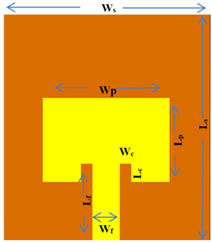
A substrate material is Rogers RT/Duroid5880 with a relative permittivity of 2.2 (loss tangent 0.0009) was used as a substrate, with 0.3451 mm of thickness. This material has a significant effect as its less losses, so it is used in millimeter wave frequencies. Copper was considered for the radiating patch and ground plane of the antenna. The ground plane reflects the surface waves and make them travel into the atmosphere [14]. As a result, the back lobes of antenna radiation pattern will be suppressed. Hence, the ground plane contributes to specific absorption rate SAR reduction. The dimensions of the radiating patch were 3.36 mm×5.18 mm×0.03 mm, representing the length (Lp), width (Wp), and thickness (t). The total occupation of the proposed design was 10 mm×8.5 mm×0.345 mm (substrate length Ls×substrate width Ws×substrate height h). These values are in the subsequent step calculated using general governing equations as given in studies [15, 16]. Figure 1 shows the schematic structure of MSPA.
2.2 Antenna design theory
The purpose of the extensive analytical study of the proposed antenna characteristics requires mathematical analysis in advance to obtain the appropriate dimensions, at which the antenna will operate on the desired frequency [17]. The resonant frequency of the antenna given as:
$f_r=\frac{c}{2(L+\Delta L) \sqrt{\varepsilon_{e f f}}}$ (1)
To compute the variation of fr in simulation and theoretical:
$\%$ var. $=\frac{\left|f_r(\operatorname{Sim} .)-f_r(T h .)\right|}{f_r(\operatorname{Sim} .)}$ (2)
For this work the variation in free space will be:
$\%$ var $\cdot_{(\text {free space })}=\frac{\mid (27.958-28) \mid}{27.958}=0.0015=0.15 \%$
Figure 1. MSPA schematic structure
Table 1. Summary of antenna dimensions
|
Parameter |
Description |
Calculated Values (mm) |
Optimized Values (mm) |
|
LP |
Length of patch |
3.40435 |
3.36 |
|
WP |
Width of patch |
4.23519 |
5.18 |
|
LS |
Length of substrate |
5.635 |
10 |
|
WS |
Width of substrate |
6.3058 |
8.5 |
|
h |
Thickness of substrate |
0.3451 |
0.33 |
|
t |
Thickness of patch |
0.0345 |
0.04 |
|
Wc |
Width of cut |
0.41 |
0.5 |
|
Lc |
Depth of cut |
1.259 |
0.74 |
|
Wf |
Width of feeder |
0.8219 |
1.1 |
|
Lf |
Length of feeder |
1.8059 |
2.7 |
The variation with human body will be:
$\%$ var $_{\cdot(\text { human body })}=\frac{\mid 28.084-28) \mid}{28.084}=0.00299=0.299 \%$
The patch width calculated as:
$W_P=\frac{c_o}{2 f_r} \sqrt{\frac{2}{\epsilon_r+1}}, c_o$ is speed of light (3)
$\epsilon_{\text {reff }}=\frac{\epsilon_r+1}{2}+\frac{\epsilon_r-1}{2}\left[1+12 \frac{h}{W_P}\right]^{-1 / 2}, W / h>1$ (4)
$\frac{\Delta L}{h}=0.412 \frac{\left(\epsilon_{\text {reff }}+0.3\right)\left(\frac{W_P}{h}+0.264\right)}{\left(\epsilon_{\text {reff }}-0.258\right)\left(\frac{W_P}{h}+0.8\right)}$ (5)
Patch length is:
$L_P=\frac{c_o}{2 f_r \sqrt{\epsilon_{\text {reff }}}}-2 \Delta L$ (6)
After calculating the dimensions according to above equations, the optimization of these values will obtain to achieve the required compact MSPA at the desired frequency. The dimensions of the proposed antenna are listed in Table 1.
In this paper, CST studio has used for simulation the electrical characteristics of human body tissues. A waveguide port has used to excite inset feed line with matching impedance equal to 50 ohms. The proposed MSPA is produced in Figure 2 with all optimized dimensions. It consists of radiating patch excited by inset feed line. This patch is above the substrate layer as a dielectric material.
(a) Front view
(b) Side view
Figure 2. Geometrical representation of MSPA
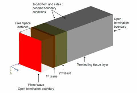
Figure 3. Geometrical structure of wave propagation onto human body tissues
The bottom important layer is the ground plane which made of copper. Figure 3 illustrates the human body layers consisting of skin, fat, and muscle tissue layers. The boundary conditions can be Periodic on top, bottom and side surfaces, to represent transverse directions, while open boundary conditions are applied on the front and back sides which are the propagation direction of the incident wave, thus, terminating the model as shown in Figure 3. The performance of the proposed antenna has analyzed taking into account the effects of cut in patch, inset feed line, and finally the ground plane dimension effect. All of these metrics have studied in free space model and on human body model.
3.1 Cut or gap in patch
S11 represents the return loss which must be less than -10 dB to consider the antenna is acceptable. Figure 4 shows the effect of cut width Wc on S11. Increasing Wc doesn't change the frequency but improve S11, while increasing patch width gives less S11 at WP=5.444 mm. The length of the cut effect is negligible as no clear effect on S11.
Figure 4. Effect of cut width in patch on S11
3.2 Inset feed line
One of the most important considerations in the design of the antenna is to obtain a perfect match at the antenna feeding network, in order to transfer the considerable amount of power from the port to the feeding line. The proposed MSPA has been excited using inset feed line. The mismatch at the feed line is significantly minimized by tuning the dimension of the inset-feed, patch width, and width of the microstrip transmission line. Thus, the greatest input power will be transmitted to the antenna with a very return loss [18]. The improvement of the antenna performance will be when the impedance mismatch between the feed network and the patch edge is reduced and measured as in the Eq. (7):
$Z_a=90 \frac{\varepsilon_r^2}{\varepsilon_r-1}\left(\frac{L_P}{W_P}\right)^2$ (7)
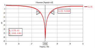
For the purpose of examining the effect of the feed line dimensions on the antenna performance, Table 2 has arranged so that the best values for the antenna dimensions achieved as feed line length=2.55 mm. These dimensions give the required resonant frequency, return loss, and matching. Figure 5 and Figure 6 illustrate S11 and impedance matching at the optimum feed line length.
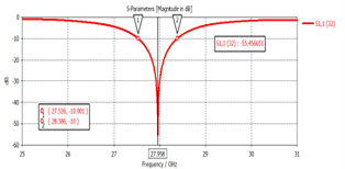
Radiation efficiency is the ratio of the power radiated by an antenna to the power accepted by the antenna from the transmitter. An antenna's gain, which combines its directivity and radiation efficiency, is a key performance indicator. Table 3 shows the extent of improvement in losses (S11=-55.45 dB), matching (Zr=49.8 Ω, Zi=0.003), -10dB Bandwidth (0.86GHz), radiation efficiency (89.4%) and gain (7.33 dBi) after changing the feed line width to get the best design. Figure 7 and Figure 8 illustrate the return loss and impedance matching respectively at optimum feed line width.
Table 2. Parametric study of feed line length on antenna performance
|
Zr+i |
S11 |
fr |
Lf |
|
40.78-5 |
-18.779 |
27.934 |
2.2 |
|
43.6-0.84 |
-23.23 |
27.946 |
2.3 |
|
44.44-0.46 |
-24.585 |
27.958 |
2.4 |
|
48.49+0.052 |
-36.32 |
28.024 |
2.5 |
|
50.86-0.055 |
-41.33 |
28.066 |
2.55 |
|
53.8+0.023 |
-49.45 |
28.11 |
2.7 |
Table 3. Effect of Wf on antenna performance
|
Gain |
Radiation Efficiency |
Zr+i |
S11 |
fr |
Wf |
|
7.36 |
89.3% |
40.2-1.2 |
-20.1 |
28 |
1.15 |
|
7.35 |
89% |
41.5-1 |
-20.66 |
27.99 |
1.1 |
|
7.341 |
89% |
43.7+0.065 |
-23.47 |
27.898 |
1 |
|
7.33 |
89.4% |
49.8+0.003 |
-55.45 |
27.958 |
0.95 |
|
7.27 |
88.7% |
53+0.06 |
-30 |
27.96 |
0.9 |
Figure 5. Return loss S11 versus frequency at Lf=2.55
Figure 6. Impedance versus frequency at Lf=2.55
Figure 7. Return loss S11 versus frequency at Wf=0.95 mm
Figure 8. Impedance versus frequency at Wf=0.95mm
3.3 Ground plane
The patch thickness and transmission line thickness are t << λ₀, where λ₀ is the free space wavelength [19]. Hence, the ground plane length (Lg) and width (Wg) would be given as:
$L_g=6 h+L_P$ (8)
$W_g=6 h+W_P$ (9)
SAR is defined as a measure for electromagnetic energy absorbed by biological tissue mass when exposed to radiating device (e.g., mobile phone). It is obtained as in Eq. (10):
$S A R=\frac{P}{\rho}=\frac{\sigma E^2}{2 \rho}=\frac{J^2}{2 \rho \sigma}$ (10)
where, P: Power loss density, E: Electric field strength, J: Current density, σ: Conductivity, ρ: Mass density.
Due to the protection of human body tissues against harmful radiation emitted from mobile phones, the upper limit of the acceptable level of SAR is set at 2 W/kg per 10 gm of the human tissue according to IEEE C95.1:2005, While a 1.6 W/kg per 1 gm of the human tissue according to Federal Communication Commission (FCC) [20, 21]. Increasing ground plane length has examined carefully to show its effect on SAR level as illustrated in Table 4. In this research, the designed body tissues, as shown in Figure 9, simulate the chest of male adult, or the arms of male adult which are: 1 mm skin, 2 mm fat, and 10 mm muscle. These choices give minor change in S11 value and the SAR is low for both cases. Dielectric properties of tissues are available online [22]. The area of tissue has taken 4 times the area of antenna [23].
Figure 9. Proposed antenna on human body tissues
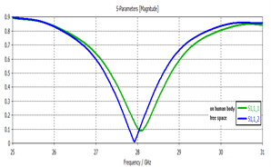
After applying antenna to a human body the resonant frequency increases lightly (28.024 GHz), S11 increases (-14.69), beside the gain increasing (7.8 dBi), but evaluation of SAR was 9.04 W/kg. Figure 10 shows the difference between antenna in free space and on human body.
The summery of both cases of simulation modes (an antenna in free space and antenna with human body) when ground plane length equal to 8.5, 10, and 12 mm can be gathered as in Table 4.
It is obvious that increasing the length of ground plane to 12 mm has a significant influence on the SAR value. SAR decreased from 9.9 W/kg to 3.5 W/kg. The gain of 12 mm ground plane antenna is the best value. While maintaining the values of the other metrics at the acceptable and desirable levels. These results will be improved by varying the power density of the proposed antenna as illustrated below. The power density can be defined as the product of an isotropic antenna's power density with its gain, it is usually calculated in mW/cm2. The input power for the antennas in 5G systems can be set to 15 dBm, 18 dBm and 20 dBm according to FCC [24, 25] to make power density of antenna less than 100 mW/cm2. In this research the SAR (1g) and SAR (10g) of the antenna at 15 dBm input power have been simulated in human body model. The SAR values are close or lower than standard limits. Figures 11, 12, and 13 demonstrate the influence of input power. The proposed antenna displays satisfactory performance in terms of resonant frequency, gain, radiation efficiency, and bandwidth. Additionally, it has a promising performance on human body application scenario.
Table 4. Effect of increasing ground plane length on SAR reduction
|
Simulation Mode |
Ground Plane Length |
fr(GHz) |
S11 |
Radiation Efficiency |
SAR(W/kg) |
Gain(dBi) |
Zr+i |
|
Free space |
8.5 mm |
27.98 |
-55.45 |
89.4% |
- |
7.33 |
49.8+ 0.003 |
|
Human body |
28.11 |
-18.9 |
81% |
9.96 |
7.76 |
39.8-0.1 |
|
|
Free space |
10 mm |
27.88 |
-39.7 |
89.3% |
- |
7.4 |
51+0.1 |
|
Human body |
28.12 |
-25 |
80.8% |
5.9 |
8.1 |
44.7-0.01 |
|
|
Free space |
12 mm |
27.92 |
-39 |
88.7% |
- |
7.4 |
51+0.1 |
|
Human body |
28.2 |
-20 |
82% |
3.54 |
8.3 |
45-0.01 |
Table 5. Comparison table with previous works
|
Ref. |
fr GHz) |
S11(dB) |
Gain (dBi) |
Radiation Efficiency |
Matching |
Complexity |
Substrate |
SAR(W/kg) |
|
[26] |
28 |
–10 |
15 |
81% |
T-junction power divider matching |
1×2 array 14×12.14 mm ² |
flame retardant |
- |
|
[23] |
2.45 |
-20 free space |
6.2 |
95% free 80% body |
approximately Matched to 50 ohm |
L_feed patch 50×50 mm2 |
polyphenylene ether (PPE) ϵ=3.3; loss tang=0.003 |
(L-shaped) 0.6414, (direct) 1.524 |
|
[27] |
28 |
-59.49 |
7.554 |
98% |
optimizing the patch width dimension |
Single patch 3.56×4.23× 0.345 mm3 |
RT/duroid-5880 ϵ=2.2; loss tang=0.0009 |
- |
|
[28] |
28 |
-25 |
18 |
- |
- |
3x8 elements array 98×32.5mm2 |
Rogers RO4003 laminate, ϵ= 3.55, tang=0.0027 |
- |
|
[29] |
28 |
-20 |
14 |
90% |
Matching by tuned the meandered line length |
6.65×4.95× 0.508 mm3 |
ogers RT/duroid 5880 ϵ=2.2; loss tang=0.0009 |
0.36 at 3.5GHz |
|
[30] |
28 |
-39.70 |
5.32 |
- |
- |
5.5×4.35 |
FR4 |
- |
|
This work |
28 |
-21 |
7.3 free space 7.2 with body |
89.4% in free space |
acceptable satisfied matching |
Single MSPA 5.18×3.36×0.3 mm3 |
RT/duroid-5880 ϵ=2.2; loss tang=0.0009 |
1.68 (1g) 0.121(10g) |
Figure 10. Realized return loss in free space and on human body
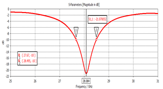
Figure 11. Return loss S11 at input power=15 dBm (antenna with human body)
Finally, the proposed antenna contributes in a reasonably SAR reduction at operating frequency when used in proximity to human body. The detailed analysis of the optimized design in terms of low profile, compactness, and SAR analysis adds to the novel aspect of our work for 5G antenna applications. This design can be used in the future to achieve a further reduction in radiation values. This is done by adding another radiating structure that suppresses the lobe towards the human body. To demonstrate the improvement and novelty of this work upon previous works, Table 5 combines some of the related recent researches in 5G.
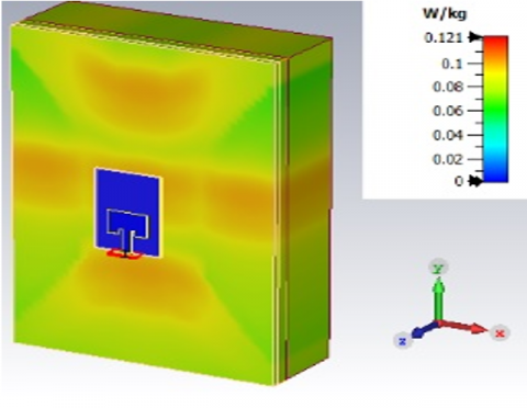
Figure 12. SAR simulation per 1g of tissue at input power=15 dBm
Figure 13. SAR simulation per 10g at input power=15dBm
This study presents the design of a broadband microstrip rectangular patch antenna for 5G wireless networks operating at 28 GHz, featuring compact dimensions of 5.18×3.36×0.33 mm³. The proposed antenna design exhibits high gain and radiation efficiency, minimal sidelobe level, and reduced SAR. Optimizing the dimensions of the patch cut and feed line has yielded satisfactory antenna performance.
Enhancing the ground plane and reducing the power density of the excited antenna have further improved the antenna's performance. This paper delineates a performance comparison in both free space and human body models, illustrating the impact of body tissues on antenna parameters. The optimization of antenna dimensions (patch cut, inset feed, and ground plane) and power density has contributed to the reduction of SAR.
The SAR value achieved is within an acceptable range, alongside improvements in other antenna metrics. These results render the designed antenna suitable for 5G applications and safe for human body tissues. The design is particularly relevant for wearable devices, the Internet of Things (IoT), and mobile wireless networks.
This work is supported by the Electrical Engineering department, College of Engineering, University of Mosul. After completing this work, here to express our thanks to encourages, advice and guidance in achieving this work.
[1] Attaran, M. (2023). The impact of 5G on the evolution of intelligent automation and industry digitization. Journal of Ambient Intelligence and Humanized Computing, 14(5): 5977-5993. https://doi.org/10.1007/s12652-020-02521-x
[2] Ullah, S., Ahmad, I., Raheem, Y., Ullah, S., Ahmad, T., Habib, U. (2020). Hexagonal shaped CPW feed based frequency reconfigurable antenna for WLAN and sub-6 GHz 5G applications. In 2020 International Conference on Emerging Trends in Smart Technologies (ICETST), pp. 1-4. https://doi.org/10.1109/ICETST49965.2020.9080688
[3] Mohammed Ali, Y.E., Abdul Qader, A.J. (2014). Design of dual band circular polarization stacked microstrip antenna for GPS applications. Al-Rafadain Engineering Journal, 22(3): 225-232. https://doi.org/10.33899/rengj.2014.88215
[4] Soh, P.J., Giman, F.N., Jamlos, M.F., Lago, H., Al-Hadi, A.A. (2016). A C-slotted dual band textile antenna for WBAN applications. In 2016 URSI Asia-Pacific Radio Science Conference (URSI AP-RASC), pp. 1621-1624. https://doi.org/10.1109/URSIAP-RASC.2016.7601404
[5] Wagih, M., Hilton, G.S., Weddell, A.S., Beeby, S. (2021). Millimeter-wave power transmission for compact and large-area wearable iot devices based on a higher order mode wearable antenna. IEEE Internet of Things Journal, 9(7): 5229-5239. https://doi.org/10.1109/JIOT.2021.3107594
[6] Khan, M.M. (2022). A novel design of a 28 GHz 5G NR MSPA antenna for body centric network. In 2022 IEEE 13th Annual Information Technology, Electronics and Mobile Communication Conference (IEMCON), pp. 0458-0464. https://doi.org/10.1109/IEMCON56893.2022.9946600
[7] Ashyap, A.Y., Abidin, Z.Z., Dahlan, S.H., Majid, H.A., Shah, S.M., Kamarudin, M.R., Alomainy, A. (2017). Compact and low-profile textile EBG-based antenna for wearable medical applications. IEEE Antennas and Wireless Propagation Letters, 16: 2550-2553. https://doi.org/10.1109/LAWP.2017.2732355
[8] Ashyap, A.Y., Elamin, N.I.M., Dahlan, S.H., Abidin, Z.Z., See, C.H., Majid, H.A., AL-Fadhali, N., Mukred, J.A.A., Saleh, G., Esmail, B.A.F. (2021). Via-less electromagnetic band-gap-enabled antenna based on textile material for wearable applications. Plos One, 16(1): e0246057. https://doi.org/10.1371/journal.pone.0246057
[9] Dhanaraj, P., Uma Maheswari, S. (2020). Performance analysis of electrically coupled SRR bowtie antenna for wireless broadband communications. Wireless Networks, 26(7): 5271-5283. https://doi.org/10.1007/s11276-020-02396-y
[10] Hakanoglu, B.G., Sen, O., Turkmen, M. (2018). A square microstrip patch antenna with enhanced return loss through defected ground plane for 5G wireless networks. In 2018 2nd URSI Atlantic Radio Science Meeting (AT-RASC), pp. 1-4. https://doi.org/10.23919/URSI-AT-RASC.2018.8471618
[11] Kumar, N., Dwivedi, R.P., Usha, P., Dubey, R., Arora, A. (2021). Design of dual-polarized compact quad band metamaterial antenna. Journal of Nano-and Electronic Physics, 13(3): 1-4. https://doi.org/10.21272/jnep.13(3).03037
[12] Wajid, A., Ahmad, A., Ullah, S., Choi, D.Y., Islam, F.U. (2022). Performance analysis of wearable dual-band patch antenna based on EBG and SRR surfaces. Sensors, 22(14): 5208. https://doi.org/10.3390/s22145208
[13] Al-azzawi, A.K. (2021). New design approach of a “2.4 GHz” slotted rectangular patch antenna with a wideband harmonic suppression. Arabian Journal for Science and Engineering, 46: 9771-9781. https://doi.org/10.1007/s13369-021-05335-x
[14] Kialashaki, M., Khaleghi, A., Taraji, M. (2021). A high‐gain cavity‐backed slot antenna using a perfect magnetic conductor ground plane and multilayered superstrates. Microwave and Optical Technology Letters, 63(3): 902-909. https://doi.org/10.1002/mop.32684
[15] Balanis, C.A. (2016). Antenna Theory: Analysis and Design. John Wiley & Sons.
[16] Sabban, A. (2021). Basic antenna theory. In low-visibility antennas for communication systems, pp. 57-80. https://doi.org/10.1201/b18919-7
[17] Chemkha, H., Belkacem, A. (2020). Design of new inset fed rectangular microstrip patch antenna with improved fundamental parameters. In 2020 IEEE International Conference on Design & Test of Integrated Micro & Nano-Systems (DTS), pp. 1-4. https://doi.org/10.1109/DTS48731.2020.9196068
[18] Luhaiby, A.A.A., Alatallah, F.S., Ali, Y., Mohammed, E. (2020). Design and implementation of tri band microstrip patch antenna with bandwidth enhancement for GSM, WLAN, WiMAX System. Rafidain Journal of Science, 29(2): 73-85. https://doi.org/10.33899/rjs.2020.165368
[19] Abdelaziem, I.H., Ibrahim, A.A., Abdalla, M.A. (2023). A high gain antenna utilizing Mu-near-zero metasurface structures for 5G applications. International Journal of Microwave and Wireless Technologies, 15(2): 338-346. https://doi.org/10.1017/S1759078722000526
[20] Javadi, K., Komjani, N. (2017). Investigation into low SAR PIFA antenna and design a very low SAR U-slot antenna using frequency selective surface for cell-phones and wearable applications. Emerging Science Journal, 1(3): 145-157. https://doi.org/10.28991/ijse-01117
[21] Nadh, B.P., Madhav, B.T.P., Kumar, M.S. (2019). Design and analysis of dual band implantable DGS antenna for medical applications. Sādhanā, 44: 1-9. https://doi.org/10.1007/s12046-019-1099-8
[22] Hasgall, P. A., Di Gennaro, F., Baumgartner, C., Neufeld, E., Lloyd, B., Gosselin, M. C., Payne, D., Klingenböck, A., Kuster, N. (2022). IT’IS Database for thermal and electromagnetic parameters of biological tissues.
[23] Guan, C.E., Fujimoto, T. (2019). Design of a wideband l-shape fed microstrip patch antenna backed by conductor plane for medical body area network. Electronics, 9(1): 21. https://doi.org/10.3390/electronics9010021
[24] Lak, A., Adelpour, Z., Oraizi, H., Parhizgar, N. (2021). Three configurations of compact planar multistub microstrip antennas for mmW mobile applications. International Journal of Antennas and Propagation, 2021: 1-10. https://doi.org/10.1155/2021/8848218
[25] Lak, A., Adelpour, Z., Oraizi, H., Parhizgar, N. (2021). Design and SAR assessment of three compact 5G antenna arrays. Scientific Reports, 11(1): 21265. https://doi.org/10.1038/s41598-021-00679-8
[26] Ghazaoui, Y., EL Ghzaoui, M., Das, S., Madhav, B.T.P., el Alami, A. (2021). A compact high gain wideband millimeter wave 1×2 array antenna for 26/28 GHz 5G applications. Circuit World. https://doi.org/10.1108/CW-10-2021-0255
[27] Fante, K.A., Gemeda, M.T. (2021). Broadband microstrip patch antenna at 28 GHz for 5G wireless applications. International Journal of Electrical and Computer Engineering, 11(3): 2238-2244. https://doi.org/10.11591/ijece.v11i3.pp2238-2244
[28] Liu, Y., Yagoub, M.C. (2021). A broadband high-gain printed antenna array using dipole and loop patches for 5g communication systems. International Journal of Mathematics and Computers in Simulation, 15(4): 42-45. https://doi.org/10.46300/9102.2021.15.8
[29] Islam, S., Zada, M., Yoo, H. (2022). Highly compact integrated Sub-6 GHz and Millimeter-wave band antenna Array for 5G smartphone communications. IEEE Transactions on Antennas and Propagation, 70(12): 11629-11638. https://doi.org/10.1109/TAP.2022.3209310
[30] Ghazaoui, Y., El Alami, A., El Ghzaoui, M., Das, S., Barad, D., Mohapatra, S. (2020). Millimeter wave antenna with enhanced bandwidth for 5G wireless application. Journal of Instrumentation, 15(01): T01003. https://doi.org/10.1088/1748-0221/15/01/T01003