Ali Mohammed Mozan![]() | Fatima Faydhe Al-Azzawi
| Fatima Faydhe Al-Azzawi![]() | Faeza Abbas Abid
| Faeza Abbas Abid![]() | Karrar A. Hammoodi*
| Karrar A. Hammoodi*![]()
© 2023 IIETA. This article is published by IIETA and is licensed under the CC BY 4.0 license (http://creativecommons.org/licenses/by/4.0/).
OPEN ACCESS
The Long Term Evolution (LTE) standard proposed by 3GPP aims to increase the availability of broadband services, with significant improvements to the LTE air interface employing various techniques. As a result, accurate channel estimation is critical for high transmission performance and system superiority. In this study, an LTE downlink system simulation program was developed to generate one frame of data on a single antenna port. The data consisted of randomly mapped bits, various modulation schemes, and coded symbols in a subframe as no transport channel was incorporated in this model. Each subframe was encoded with cell-specific reference signals, primary and secondary synchronization signals. To construct a frame, 10 subframes were generated independently. The frame was modulated using the LTE standard, passed through an Extended Vehicular A Model (EVA5) fading channel with additive white Gaussian noise (AWGN), and then demodulated. Finally, the received and equalized resource grid for all modulation types were displayed using minimum mean square error (MMSE) equalization with channel and noise estimates. The percentage root mean square error vector magnitude (RMS EVM) of the pre- and post-equalized signals were calculated.
LTE equalizer, MMSE, RMS EVM
Equalization refers to the reversal of waveform distortion caused by transmission across a channel in telecommunications. Once a channel has been equalized, the frequency domain properties of the input signal are faithfully reproduced at the output. Equalizers condition data signals for transmission through telephones, digital subscriber lines (DSL), and television connections [1, 2].
Equalizers are essential for the proper functioning of electronic systems like analog broadcast television. In these applications, not only the frequency content but also the phase and group delay between various frequency components of the actual transmitted signal must be negated by equalizing filters [3, 4]. In modern digital telephone networks, only the local line to the customer remains in analog format. However, DSL signals in the MHz range on those cables can suffer severe attenuation distortion, which is mitigated by automated equalization or by discarding the most affected frequencies. Equalizers were also incorporated in early picturephone systems [5, 6].
In digital communications, the role of equalizers is to eliminate inter-symbol interference so that the transmitted signals can be recovered. Equalizers can range from simple linear filters to complex algorithms [7, 8].
Data rates of up to 3 Gbps will be enabled by the recent mobile communications standard, LTE, which utilizes powerful tools for handling frequency selective channels [8, 9]. Good channel estimation is required to reconstruct the transmitted symbols and achieve optimal performance. For LTE Advanced, the development of an embedded system comprising a channel estimator and equalizer may be implemented. MATLAB can be used to compare existing methods and develop a cost-effective solution suitable for software implementation [9, 10].
In this study, an LTE downlink system simulation program was developed to generate one frame of data on a single antenna port. The data consisted of randomly mapped bits, various modulation schemes, and coded symbols in each subframe as no transport channel was incorporated in this model. Each subframe was encoded with cell-specific reference signals, primary and secondary synchronization signals. To construct a frame, 10 subframes were generated independently. The frame was modulated using the LTE standard, passed through an Extended Vehicular A Model (EVA5) fading channel with additive white Gaussian noise (AWGN), and then demodulated. Finally, the received and equalized resource grids for all modulation types were displayed using minimum mean square error (MMSE) equalization with channel and noise estimates. The percentage root mean square error vector magnitude (RMS EVM) of the pre- and post-equalized signals were calculated.
A complete LTE downlink system with, related estimation of channel, and equalization along with wireless channel and noise are shown in Figure 1, physical downlink shared channel NPDSCH is used as channel of the leading data-bearing by the transmitter downlink (LTE) [11, 12]. Input binary information reaches to the coding unit as a single block transport for a number of resource blocks (RB) in every downlink cell. The scheduling of RB is arranged according to the study [8]. According to 3GPP [9], the NPDSCH data processing sequence contains transport block cyclic redundancy check (CRC) attachment. Finally, NPDSCH gets the input after the operation of rate matching [13, 14].
Figure 1. LTE downlink system block diagram
2.1 Cell settings and SNR configuration
Where several functions used in this model requires settings as fallowing: Number of resource block, No. of transmit antenna, cell ID, cyclic prefix, duplexing mode. The SNR dB value, which is also translated into a linear SNR, is used to specify the operating SNR in decibels [15].
2.2 Channel model and estimator
A structure is used to configure the channel model. This model employs a fading channel with a 120Hz Doppler frequency and an Extended Vehicular A (EVA) delay profile. Those parameters are determined, as well as MIMO correlation and other channel model-specific factors. To limit the effect of noise, window with user-defined is employed to symbols that average pilot. The size of the average window is depended on resource elements (REs), frequency, and time [16, 17]. As 120Hz Doppler frequency and an EVA delay profile allow the channel to fluctuate quickly over frequency and time, a conservative 9-by-9 window is employed in this case. When averaging, the four pilot's area surrounding the pilot of focus are included in a 9-by-9 window. Channel estimation topics cover how to choose an averaging window [18, 19]. The estimation of channel interpolates between estimated pilot to obtain a channel estimation for all REs. When interpolating, numerous subframes might be employed to increase the approximation. The center subframe is estimated using pilot estimates from three successive subframes in a three-subframe interpolation window with a centered interpolation window.
2.3 Generation of payload data
The data transferred through the channel will be random because no transport channel is employed in this scenario. BPSK, QPSK, 16 QAM, 64 QAM, 265 QAM and 1024 QAM modulated symbols. A subframe of symbols is established so that each resource element can be mapped to a symbol. These symbols in the resource grid will be overwritten by other signals required for transmission and reception [20, 21].
2.4 Generation of frame
Individual subframes will be generated in a loop, and each new subframe will be appended to the preceding subframes to create the frame. The group of attached subframes is analyzed. To make a frame, this adding is performed ten times. When an OFDM modulated time domain signal is transmitted via a channel, it experiences a delay [22, 23]. To ensure that no samples are missing as a result of the delay, one additional subframe is produced, making a total of 11 subframes. The addition of Cell-Specific Reference Signal (Cell RS) operation to each subframe. Also included are Secondary Synchronization Signal (SSS) and the Primary Synchronization Signal (PSS) [24, 25].
2.5 Multi carrier modulation
OFDM modulation is necessary to convert frequency domain LTE symbols to time domain symbols. A matrix transmitter waveform and a structure information that have a sampling rate are returned by the function. The waveform with time domain that resulting is known as the Transmitter Waveform [26]. The signal of time domain for every port of antenna is contained in each column. Because just one port of antenna that used in this case, returning of only one column is occur, the sample rate used to construct the time domain waveform. The channel model requires this value [27].
2.6 Additive noise: SNR calculated as follows
Where is the signal energy that interest and as noise power. The FFT will amplify the noise injected before OFDM demodulation. As a result, the noise must be adjusted for normalizing the SNR in the receiver pre OFDM demodulation. The amplification factor measured as the FFT size with square root of. The sampling rate of the subcarrier spacing and the time domain waveform can be used to calculate the size of the FFT (15 kHz). To obtain the desired SNR (SNR dB). After OFDM demodulation, the noise power that introduced can be scaled so that are normalized [28, 29].
2.7 Multicarrier demodulation
In this stage there will be converting time to frequency domain waveform then generating a resource grid, OFDM demodulation is used. The outcome is a three-dimensional matrix grid. The subcarriers numbers are represented by the rows number. The columns number in a subframe equals the number of OFDM symbols. The output grid from OFDM decoding has the same number of subcarriers and symbols as the grid input into LTE OFDM Modulate [11, 26].
2.8 Channel estimation
The following are the steps involved in channel estimate processing [1, 2]:
From the received grid, recover the reference signals (pilot symbols) for a receive - transmit antenna. Calculate the least-squares estimations response of the channel at the pilot symbol points within a received grid using the reference signals. By dividing the received pilot symbols by their predicted value, the function provides the least-squares estimates of the reference signals. The least-squares estimations are affected by any system noise. To establish a realistic assessment of the channel at pilot symbol places, remove or minimize the noise.
To minimize any undesired noise from the pilot symbols, average the least-squares estimates.
For the whole number of subframes supplied into the function, interpolate the cleaned pilot symbol estimates into a channel estimate.
2.9 MMSE equalization
The minimum Mean-Squared Error (MSE) method [4] uses the block diagram shown in Figure 2 to calculate the coefficients of equalizer. The impulse response of equalizer would be equal to the target impulse response (TIR) with a time delay deference if the error in Figure 2 could be driven to zero. We can control the length of the equalized channel by adjusting the TIR length. The purpose is to find the optimum TIR and an equalization that minimizes the MSE given the duration of the TIR [1, 2].
At MSE minimum, the equalizer and TIR have to satisfy:
$b^T R_{x y}=w^T R_{y y}$ (1)
where, the input-output Rxy and Ryy cross correlation and the matrices of output autocorrelation, respectively. So:
$M S E=b^T\left[R_{x x}-R_{x y}-R_{y y}^{-1} R_{y x}\right] b=b^T R_{x y} b$ (2)
To prevent solution of the trivial b=0, adding a constraint on b, the equalizer design problem becomes:
$\min _b b^T R_{x y} b s \cdot t\|b\|=1$ (3)
The solution by b is Rx/y eigenvector depending on the minimum eigenvalue. The settings of corresponding equalizer can be valued by (1).
LTE Equalize MMSE is used to equalize the effects of the channel on the received resource grid. To equalize the received resource grid, this function employs the channel and noise estimates. The grid that equalized has similar dimensions as the reference grid before modulation of OFDM [7, 8].
Figure 2. MMSE equalize
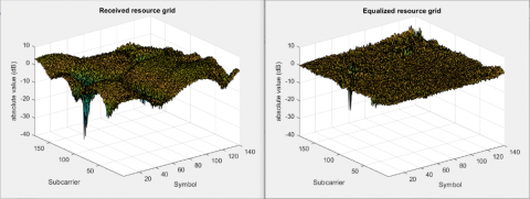
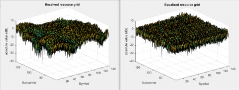
The equalized resource grid is compared to the resource grid that was received. It is estimated the difference between the equalized and transmitted grids, as well as the received and transmitted grids. This results in two matrices having the size of the resource arrays containing each symbol with error. RMS EVM % of Pre-Equalized signal and RMS EVM % of Post-Equalized signal are calculated and illustrated in Tables 1 and 2 for deferent Modulation Mapping, where 1024 QAM performance shows minimum Percentage RMS EVM of Pre-Equalized reaches to 123.693% while 64 QAM have least Percentage RMS EVM of Post-Equalized reaches to 15.511%.
The equalized and received grids are shown on a logarithmic scale for easier viewing. for modulation schemes used in the model (BPSK, QPSK, 16 QAM, 64 QAM, 265 QAM and 1024 QAM) as shown in Figures 3-8 respectively. These figures show how equalization of channel minimize the inaccuracy in the resource grid that received significant.
Table 1. EVM of pre-equalized signal and RMS and post-equalized signal with BPSK, QPSK and 16-QAM
|
|
BPSK |
QPSK |
16-QAM |
|
Percentage RMS EVM of pre-equalized signal |
124.220% |
124.133% |
124.153% |
|
Percentage RMS EVM of post-equalized signal |
16.096% |
15.598% |
15.572% |
Table 2. EVM of pre-equalized signal and RMS and post-equalized signal 64 QAM, 256 QAM, 1024 QAM
|
|
64-QAM |
256 QAM |
1024 QAM |
|
Percentage RMS EVM of pre-equalized signal |
124.308% |
124.202% |
123.693% |
|
Percentage RMS EVM of post-equalized signal |
15.511% |
15.967% |
15.600% |
Figure 3. Received resources grid and equalized resources grid with BPSK mapping
Figure 4. Received resources grid and equalized resources grid with QPSK mapping
Figure 5. Received resources grid and EQUALIZED resources grid with 16 QAM mapping
Figure 6. Received resources grid and equalized resources grid with 64-QAM mapping
Figure 7. Received resources grid and equalized resources grid with 256 QAM mapping
Figure 8. Received resources grid and equalized resources grid with 1024 QAM mapping
LTE- Downlink system simulation program creates data frame in antenna one port. With no channel transporting is generated in this model, data as random bits, multi modulation schemes and codded to each subframe symbol. RMS EVM % of Pre- signal Equalized and RMS EVM% of Post- signal Equalized are calculated and illustrated in Table 1 for deferent Modulation Mapping, where 1024 QAM performance shows minimum Percentage RMS EVM of Pre-Equalized reaches to 123.693% while 64 QAM have least Percentage RMS EVM of Post-Equalized reaches to 15.511%. Reference signal with cell-specific as well as primary and secondary synchronization signals. To make a frame, 10 subframes are generated independently. The frame is LTE modulated, then demodulated after passing through an EVA5 fading channel with AWGN. demodulated after addition. MMSE equalization using estimation of noise and channel, where applied and finally the equalized and received resource grids are plotted in all modulation type. Accordingly, estimation of exact channel technology is major technique the high transmission performance and ensures the system superiority.
[1] Ibrahim, I.A.A., Jubara, H.E. (2016). Investigation of LTE receivers in term of channel equalization techniques in LTE downlink. International Journal of Science and Research (IJSR), 5(6): 106-111. http://dx.doi.org/10.21275/v5i6.NOV164074
[2] Ketonen, J. (2012). Equalization and channel estimation algorithms and implementations for cellular MIMO-OFDM downlink. Doctoral dissertation, University of Oulu, Finland.
[3] Mathai, V., Sagayam, K.M. (2013). Comparison and analysis of channel estimation algorithms in OFDM systems. International Journal of Scientific & Technology Research, 2(3): 76-80.
[4] Dawar, V., Sharma, R. (2012). Reduction in bit error rate from various equalization techniques for MIMO technology. International Journal of Soft Computing and Engineering (IJSCE), 2(4): 66-70.
[5] Hanzo, L., Choi, B.J. (2007). Near-instantaneously adaptive HSDPA-style OFDM versus MC-CDMA transceivers for WIFI, WIMAX, and next-generation cellular systems. Proceedings of the IEEE, 95(12): 2368-2392. https://doi.org/10.1109/JPROC.2007.904445
[6] Holma, H., Toskala, A. (2011). LTE for UMTS: Evolution to LTE-Advanced. John Wiley & Sons, Ltd, Chichester.
[7] Jewel, M.K.H., Zakariyya, R.S., Lin, F. (2021). On channel estimation in LTE-based downlink narrowband Internet of Things systems. Electronics, 10(11): 1246. https://doi.org/10.3390/electronics10111246
[8] 3rd Generation Partnership Project; NB-IoT; Technical Report on Physical layer procedures; Evolved Universal Terrestrial Radio Access (E-UTRA). 3GPP Technical Specification Group Radio Access Network, 2018, V15.2.0, Rel.15, TS36.213. Available online: http://www.3gpp.org/ftp/Specs/archive/36_series/36.213/36213-d40.zip, accessed on 26 March 2021.
[9] 3rd Generation Partnership Project; NBIoT; Technical Report on Multiplexing and Channel Coding; Evolved Universal Terrestrial Radio Access (E-UTRA). 3GPP Technical Specification Group Radio Access Network, 2018, V 15.2.0, Rel. 15, TS 36.212. Available online: http://www.3gpp.org/ftp/Specs/archive/36_series/36.212/36212-d40.zip, accessed on 26 March 2021.
[10] Arslan, G., Evans, B.L., Kiaei, S. (2000). Optimum channel shortening for discrete multitone transceivers. In 2000 IEEE International Conference on Acoustics, Speech, and Signal Processing. Proceedings (Cat. No. 00CH37100), Istanbul, Turkey, pp. 2965-2968. https://doi.org/10.1109/ICASSP.2000.861156
[11] Al-Azzawi, F.F., Emad, S.A. (2006). Effect of multi-tone jamming on FH-OFDMA system with orthogonal hopping patterns. In 2006 IEEE GCC Conference (GCC), Manama, Bahrain, pp. 1-5. https://doi.org/10.1109/IEEEGCC.2006.5686256
[12] Al-Azzawi, F.F., Al-Azzawi, Z.F., Shandal, S., Abid, F.A. (2020). Modulation and RS-CC rate specifications in WiMAX IEEE 802.16 Standard with MATLAB Simulink model. IOP Conference Series: Materials Science and Engineering, 881(1): 012109. http://doi.org/10.1088/1757-899X/881/1/012109
[13] Faydhe al-azzawi, F. (2019). LTE RF receiver modeling and each part testing with MATLAB Simulink. Indonesian Journal of Electrical Engineering and Computer Science, 14(3): 1251-1257. http://doi.org/10.11591/ijeecs.v14.i3.pp1251-1257
[14] Al-Azzwi, F.F., Khamees, R.A., Lateef, Z.A., Al-Azzawi, B.F. (2022). Specification of downlink-fixed reference channel DL-FRC for 5G new radio technology. International Journal of Electrical and Computer Engineering (IJECE), 12(1): 453-459. http://doi.org/10.11591/ijece.v12i1.pp453-459
[15] Al-Azzawi, F.F., Abid, F.A., Naji, M.K. (2022). Radio frequency receiver of long-term evolution system design by MATLAB Simulink. TELKOMNIKA (Telecommunication Computing Electronics and Control), 20(2): 244-251. http://doi.org/10.12928/telkomnika.v20i2.20936
[16] Al-Azzawi, F.F., Lateef, Z.A., Mozan, A.M. (2021). Perfect channel estimation of LTE downlink performance under HST condition. In 2021 International Conference on Communication & Information Technology (ICICT), Basrah, Iraq, pp. 152-155. https://doi.org/10.1109/ICICT52195.2021.9568466
[17] Fatima, B. (2019). The channel shortening comparison between OFDM & MC-CDMA system over an ADSL channel using a water-filling. International Journal of Electrical and Computer Engineering, 9(5): 3695-3700. http://doi.org/10.11591/ijece.v9i5.pp3695-3700
[18] Leftah, H.A., Alminshid, H.N. (2019). Channel capacity and performance evaluation of precoded MIMO-OFDM system with large-size constellation. International Journal of Electrical and Computer Engineering, 9(6): 5024-5030. http://doi.org/10.11591/ijece.v9i6.pp5024-5030
[19] Chung, G.C., Alias, M.Y., Tiang, J.J. (2017). Bit-error-rate optimization for CDMA ultra-wideband system using generalized gaussian approach. International Journal of Electrical and Computer Engineering, 7(5): 2661-2673. http://doi.org/10.11591/ijece.v7i5.pp2661-2673
[20] Al Ibraheemi, H., Al Ibraheemi, M.M. (2020). Wireless communication system with frequency selective channel OFDM modulation technique. TELKOMNIKA (Telecommunication Computing Electronics and Control), 18(3): 1203-1208. http://doi.org/10.12928/telkomnika.v18i3.14683
[21] Bouasria, F., Djebbari, A., Chetioui, M. (2019). A blind channel shortening for multiuser, multicarrier CDMA system over multipath fading channel. TELKOMNIKA (Telecommunication Computing Electronics and Control), 17(4): 1692-1697. http://doi.org/10.12928/telkomnika.v17i4.11400
[22] Al-Hilfi, H.M.T. (2020). Analysis of LTE physical channels overhead. TELKOMNIKA (Telecommunication Computing Electronics and Control), 18(5): 2800-2806. http://doi.org/10.12928/telkomnika.v18i5.16701
[23] Boby, R.I., Abdullah, K., Jusoh, A.Z., Parveen, N., Asnawi, A.L. (2019). A wireless precoding technique for millimetre-wave MIMO system based on SIC-MMSE. TELKOMNIKA (Telecommunication Computing Electronics and Control), 17(6): 2782-2789. http://doi.org/10.12928/telkomnika.v17i6.12802
[24] Myung, H.G., Lim, J., Goodman, D.J. (2006). Single carrier FDMA for uplink wireless transmission. IEEE Vehicular Technology Magazine, 1(3): 30-38. https://doi.org/10.1109/MVT.2006.307304
[25] Nisar, M.D., Nottensteiner, H., Hindelang, T. (2007). On performance limits of DFT spread OFDM systems. In 2007 16th IST Mobile and Wireless Communications Summit, Budapest, Hungary, pp. 1-4. https://doi.org/10.1109/ISTMWC.2007.4299159
[26] Falconer, D., Ariyavisitakul, S.L., Benyamin-Seeyar, A., Eidson, B. (2002). Frequency domain equalization for single-carrier broadband wireless systems. IEEE Communications Magazine, 40(4): 58-66. https://doi.org/10.1109/35.995852
[27] Priyanto, B.E., Codina, H., Rene, S., Sorensen, T.B., Mogensen, P. (2007). Initial performance evaluation of DFT-spread OFDM based SC-FDMA for UTRA LTE uplink. In 2007 IEEE 65th Vehicular Technology Conference-VTC2007-Spring, Dublin, Ireland, pp. 3175-3179. https://doi.org/10.1109/VETECS.2007.650
[28] Abid, F.A., Al-azzawi, F.F., Hadi, N.R. (2020). Specification parameters of WLAN performance with MatLab Simulink model of IEEE 802.11. IOP Conference Series: Materials Science and Engineering, 745(1): 012056. https://doi.org/10.1088/1757-899X/745/1/012056
[29] Al Azzawi, F.F., Al Azzawi, Z.F., Al Azzawi, S.F., Abid, F.A. (2020). Reference measurement channel RMC parameters of LTE downlink waveforms. IOP Conference Series: Materials Science and Engineering, 881(1): 012107. https://doi.org/10.1088/1757-899X/881/1/012107