Hasan S. Majdi![]() | Basil N. Merzah*
| Basil N. Merzah*![]() | Sanaa T. Mousa Al-Musawi
| Sanaa T. Mousa Al-Musawi![]() | Atheer R. Abdullah
| Atheer R. Abdullah![]()
© 2023 IIETA. This article is published by IIETA and is licensed under the CC BY 4.0 license (http://creativecommons.org/licenses/by/4.0/).
OPEN ACCESS
To increase gas turbine power output and thermal efficiency, turbine inlet temperatures can exceed the melting point of component materials. Blade cooling techniques are thus required. This study reviews external cooling methods for gas turbine blade tips. Recent publications on cooling technology improvements were analyzed to enhance turbine blade cooling. The operating conditions and cooling requirements of turbine blades were examined. Air was blown through a duct in the turbine blade at lower temperatures to cool the blade by adjusting the air pressure to match internal pressures. The inlet air pressure was 24,000 Pa. Experiments were conducted by varying the air pressure. At 25,000 Pa, the air flow improved. Increasing the pressure to 30,000, 35,000, and 40,000 Pa resulted in the cooled air flowing away from the blade, causing blockage and reduced inlet air pressure. Reducing the pressure to 24,000 Pa caused the air to be retained, preventing its exit through the holes and increasing blade temperature. The optimal cooling was achieved at 25,000 Pa.
cooling turbine edge, CFD, cooling techniques, FEM, gas turbine, outer cooling, sharp edge tip heat moves, thermal hydraulic performance
Reports analyzing cooling performance of flat tip and cambered tip blades have been reviewed and discussed. As a concluding remark, the key factors found to significantly impact blade tip thermal performance were identified as tip clearance aspect ratio and coolant flow rate [1]. Turbine blade cooling has been investigated in a multidisciplinary manner using sequentially coupled heat transfer analysis and stress analysis with temperature and pressure increments. Uncertainty factors such as blade wall thickness and rib geometry have been considered. The Kriging surrogate model is well known for reducing time-consuming interdisciplinary reliability analyses in the RBMDO framework [2].
V- and W-shaped ribs may provide good thermal hydraulic performance (THP) in a limited length along the leading edge of a gas turbine operating at high temperatures. Variations in heat transfer and flow were found to be greater for V-ribs than for the other rib types analyzed. At a Reynolds number of 40,000, the effect of ribs on heat transfer and friction was reportedly significant. Studies of V- and W-ribs revealed severe flow disturbance enhancements for Reynolds numbers ranging from 20,000 to 80,000 [3]. Few studies have investigated the effects of pulsation instability in turbine cooling blades. The introduction of the pulsed jet toward the suction and pressure sides of the blade was clearly affected by pulsation frequency and amplitude. Mixing of the pulsed air with the mainstream was greater on the pressure side than on the suction side. Under certain conditions, the pulsed jet’s effect at the center of film cooling effectiveness was more significant than the steady jet [4].
In advanced applications, turbine inlet temperatures of 1,500–2,000 K have become standard. First-stage blades are particularly exposed to such hot gases and require intensive cooling. A basic thermodynamic model of blade cooling based on mass/energy balances and heat transfer correlations has been proposed, predicting a one-dimensional temperature profile along the blade for a given gas profile [5]. Numerical experiments were performed to examine the effects of round-to-shaped film cooling holes on a multi-passage film-cooled turbine blade under representative engine flow conditions. Four film-hole shapes were considered: merging round-to-rectangular hole (RTSH-1), identical position round-to-rectangular hole (RSH-2), and diffusing fan-shaped hole (FSH-3). According to the findings, RTSH-2 should be selected as it has the best form and coolant usage total, enthalpy drop coefficient, and cooling effectiveness. The present study focuses only on varying the film-hole shape at the suction and pressure sides while the showerhead film cooling holes at the leading edge remain round and cylindrical [6].
Thermal barrier coating (TBC) acts as a protective layer, creating a temperature gradient between the hot gases and blade substrate. TBC thicknesses ranging from 100 to 500 μm resulted in a reduction of plastic strain on multiple instances. The primary region near the blade surface, which can be deemed a potential site for crack nucleation, may be examined using stress analysis [7]. The coolant chamber is intricately designed to obtain flow fields closer to the actual blade cooling system. The 3D steady Reynolds-averaged Navier–Stokes (RANS) equations and the k-ω turbulence model were used in the numerical computation. Results revealed that the coolant chamber increases the mass flow rate of jets from upstream to downstream [8].
Due to flow reattachment, film cooling with multiple rows of holes promotes detachment of the coolant film and limited cooling over a confined region. Showerhead cooling offers 34% and 25% higher cooling capacity than cascade and internal cooling, respectively [9]. In the leading edge region of a gas turbine blade, jet impingement cooling has been widely employed. The effect of jet impinging location on leading edge heat transfer was the focus of this study. A semi-circular and hollow plate, side exit slots, and an impingement flow plate comprised the test rig. The Reynolds number of the flow was varied from 10,000 to 30,000 [10].
At different Reynolds numbers and temperature ranges, the heat transfers and flow characteristics in a vortex cooling arrangement with 5 nozzles were investigated. Results indicated that the k-ω turbulence model predicts vortex cooling behavior with the greatest accuracy. In all cases, high Nusselt number regions emerge below each nozzle, while air from downstream is readily entrained due to the “counter crossflow blockage” effect [11]. An impingement jet was studied with a curved target plate simulating the leading edge of a turbine. The array consisted of nine round jets with a diameter Dijet and a bending radius R = Dijet on the target plate. A smaller pitch distance enhances crossflow effects and increases the overall heat transfer level [12]. A spin tube is an effective cooling solution for applications with hot stacked elements such as gas turbine blades. These guide vanes shorten an inherently 3D swirling flow and an enhanced turbulence in the chamber, thus increasing the convective heat transfer. Spin tubes with multiple inlets have lower maximum heat transfer rates than spin tubes with a single inlet due to reduced flow velocity [13].
In this study, the presence experiments simulating the service condition were conducted, and the presence assumption modeling as well as fatigue crack nucleation were completed for the film cooling design of a single crystal (SC) turbine blade. Given the observations, it appears that microcrack nucleation near the hole edge was triggered by persistent slip bands (PSBs). The relevant microstructure was selected to be the microstructural barrier that most controls the accumulation rate and propagation of PSBs [14].
Under constant temperature or constant heat flux boundary conditions, enhanced rectangular or square channels are commonly adopted for targeting turbine blade internal cooling attributes. The internal heat transfer and friction losses in a channel with two types of rib-roughened walls, Model A with 60° inclined ribs and Model B with 60° V-shaped ribs, are presented in this study. Fixed and two rotating conditions with rotation numbers Ro = 0.1 and 0.2 were considered [15].
Protocols ensure the elimination of communication errors and deadlocks as well as demonstrate liveness. A provably MPST-correct protocol that employs an acquire/release synchronization structure has been presented. Essentially, the approach achieves thread safety by maintaining a synchronization predicate liveness invariant during protocol execution. The protocol structure does not rely on global module types and does not employ syntactic duality checks [16].
To enhance heat transfer and reduce pressure loss, a wavy rib with progressive inclination was proposed for the internal cooling passage in a turbine blade. The numerical study focused on the heat transfer performance and flow characteristics of a single pass, stationary channel with wavy ribs. The baseline 45° V-shaped ribs with high flow disturbance enhancement were selected as the wavy rib reference design [17].
At a low-speed cascade source, the film cooling effectiveness of showerhead holes was identified from fan-shaped holes. Showerhead holes showed reduced sensitivity to film hole location and length to diameter ratio. The greater the distance between the film hole and the blade leading edge, the greater the film cooling effectiveness. Furthermore, the amount of camber had a beneficial effect on the film cooling effectiveness [18].
Recuperation technology can be used in gas turbine applications to increase efficiency and reduce fuel consumption. In this study, the coolant mass flow rate is not fixed for each cycle and over a wide range of operational conditions. The efficiency criterion is not completely rigid and provided based on the extracted air from the compressor. The analysis of a helicopter engine was investigated [19].
The aryl hydrocarbon receptor (AhR) is a transcriptional factor that is predominantly expressed in immune cells. The AhR signaling pathway relies on its ligands, which are present in the environment and can also be generated through metabolism. Combining AhR ligands or drugs has been shown to be effective for treating autoimmunity in a few immune system diseases or models [20].
Before being ejected as film cooling, the coolant often passes through internal passages that may include impingement on the inner surface of a turbine component. External film cooling is commonly assessed using adiabatic effectiveness and its impact on the external heat transfer coefficient. By selectively blocking certain holes and measuring how the overall effectiveness changed, the overall contribution of film cooling within the holes was studied [21].
In gas turbines, hot combustion gas may be ingested through the gap between blade stages. The blade stage below is supplied with purge air to prevent hot gas ingestion. Seals are often employed at this gap to reduce the requirement for purge air. This study investigated the effect of a seal on the effectiveness of film cooling and heat transfer on the stage [22].
The experiments were conducted on an instantaneous cascade with a Reynolds number of 3.85 and the blade cascade at maximum lift condition. The wake Strouhal number was varied from 0 to 0.36, and three purge flow ratios were not firmly established. The results show that under high turbulence intensity and weak wake conditions, the effect of purge flow ratio on film cooling effectiveness decreases [23].
The review analyzes two innovative configurations of the aerodynamic pin fins in wedge-shaped channels, demonstrating the potential for flow manipulation and heat transfer enhancement for the turbine blade internal cooling. The experiments show that the aerodynamic shape of the guiding pin fins results in much lower pressure losses compared to the baseline indirect pin fin arrays. Also, as the Reynolds number increases, the heat transfer enhancement and pressure drop reduction provide more substantial improvements for the guiding pin fin models [24]. The preliminary results of the cooling performance of multiple rows of film cooling holes on the suction surface of a turbine blade were presented. The effects of hole configuration, compound angle, and hole performance were investigated. Pressure sensitive paint (PSP) was employed to achieve sufficient adiabatic film cooling. According to the results, the superposition principle was entrapped by internal flow redirection [25].
Many studies [26-36] have investigated heat transfer enhancements and characteristics in various complex enclosures and configurations using multiple techniques and materials. It was concluded that these techniques aid in enhancing heat transfer and thus improving the efficiency of these systems and test rigs.
Simulation of the optimization model for turbine blade cooling requires engineering software design, and the model was built using Solidworks software, as shown in Figure 1. The dimensions of the feather according to the international standards for the turbine gas feather and the details are taken from the guideline [37].
Figure 1. Geometry of blade
In order to make the model simulated with CFD program, the fluid path and the internal and external domains of the blade must be set according to the dimensions in Figure 2. The selection of the air location applies to placing the cooling duct in a manner adjacent to the turbine in order to sufficiently cool the turbine blade. It should not be in a way that opposes the duct of the air, which may reduce the efficiency of the turbine. The diameter of the air pipe is 6 mm.
Figure 2. Geometry design
After the process of designing the model and starting the simulation using the Ansys CFD program, an engineering program simulates thermal systems and airflow. Where a suitable mesh must be made for obtaining accurate results that can be compared to practical applications, where the mesh reliability and mesh increase until a stable result is reached as shown in Figure 3. A tetrahedral grid was used with a number of elements amounting to 663,861, since the temperature in this case was stable and its value was 621.6 K as shown in Table 1.
Figure 3. Geometry mesh
Table 1. Mesh independency
|
Case |
Element |
Node |
Outlet temperature (k) |
|
1 |
312631 |
723672 |
602.6 |
|
2 |
425722 |
938624 |
619.4 |
|
3 |
532541 |
1125321 |
621.1 |
|
4 |
663861 |
1291770 |
621.6 |
After the network work process, the appropriate settings are set to achieve the simulation condition where different pressures are used at the cooling area (25,000 Pa, 30,000 Pa, 35,000 Pa 40,000 Pa, 45,000 Pa). Where the k-e model was used, as this model is considered one of the models that gives results matching the truth as it is known from the research. In the previous case, where the pressure of entering the inlet stream of the turbine was added 24,000 Pa and at a temperature of 1200 K, where these cases were based on making a comparison between them and obtaining the most condition. In which the flow could be attached to the outer layer of the blade to make cooling with high efficiency. As for the simulation time, where the simulation process was devoid of time the change is state.
The condition for the state of movement is as per the following:
$\frac{\partial \rho }{\partial t}+\nabla \cdot \left( \rho \vec{v} \right)={{S}_{m}}$ (1)
In equation one, it is on account of general movement, yet in Eq. (2), the condition is as a heading, or at least, it is in an extraordinary case, as it is given in the accompanying structure.
$\frac{\partial \rho }{\partial t}+\frac{\partial }{\partial x}\left( \rho {{v}_{x}} \right)+\frac{\partial }{\partial r}\left( \rho {{v}_{r}} \right)+\frac{\rho {{v}_{r}}}{r}={{S}_{m}}$ (2)
where, x is the fundamental heading, r is the winding bearing, vx is the middle speed, and vr is the drawn-out speed. Protection of force in an inertial (non-speeding up).
$\frac{\partial }{\partial t}\left( \rho \vec{v} \right)+\nabla \cdot \text{ }\!\!~\!\!\text{ }\left( \rho \vec{v}\vec{v} \right)=-\nabla p+\nabla \cdot (\overline{\overline{\tau )}}+\text{ }\!\!~\!\!\text{ }\rho \vec{g}+\vec{F}$ (3)
where, p is the static strain, $(\overline{\overline{\tau )}}$ is the strain tensor (depicted under), $\rho \vec{g}$and $\vec{F}$are the gravitational body power and outside body powers (for instance, that emerge from relationship with the scattered stage), autonomously. $\vec{F}$similarly contains other model-subordinate source terms, for example, permeable media and client depicted sources. The strain tensor $(\overline{\overline{\tau )}}$ is given by:
$\overline{\overline{\tau }}=\mu \left[ \left( \nabla \vec{v}+\nabla {{{\vec{v}}}^{T}} \right)-\frac{2}{3}\nabla \cdot \vec{v}I \right]$ (4)
where, μ is the atomic consistency, I is the unit tensor, and the second term on the right hand side is the impact of volume expansion. For 2D axisymmetric calculations, the middle point and expanded power affirmation conditions are given by:
$\begin{aligned} & \frac{\partial}{\partial t}\left(\rho v_x\right)+\frac{1}{r} \frac{\partial}{\partial x}\left(r \rho v_x v_x\right)+\frac{1}{r} \frac{\partial}{\partial r}\left(r \rho v_r v_x\right)=-\frac{\partial p}{\partial x}+\frac{1}{r} \frac{\partial}{\partial x}\left[r \mu\left(2 \frac{\partial v_x}{\partial x}-\frac{2}{3}(\nabla \cdot \vec{v})\right)\right] \\ & +\frac{1}{r} \frac{\partial}{\partial r}\left[r \mu\left(\frac{\partial v_x}{\partial r}+\frac{\partial v_r}{\partial x}\right)\right]+F_x\end{aligned}$ (5)
and
$\begin{aligned} & \frac{\partial}{\partial t}\left(\rho v_r\right)+\frac{1}{r} \frac{\partial}{\partial x}\left(r \rho v_x v_r\right)+\frac{1}{r} \frac{\partial}{\partial r}\left(r \rho v_r v_r\right)=-\frac{\partial p}{\partial r}+\frac{1}{r} \frac{\partial}{\partial x}\left[r \mu\left(\frac{\partial v_r}{\partial x}+\frac{\partial v_x}{\partial r}\right)\right] \\ & +\frac{1}{r} \frac{\partial}{\partial r}\left[r \mu\left(2 \frac{\partial v_r}{\partial r}-\frac{2}{3}(\nabla \cdot \vec{v})\right)\right]-2 \mu_{r_r}^{v_r}+\frac{2}{3} \frac{\mu}{r}(\nabla \cdot \vec{v})+\rho \frac{v_r}{r}+F_r\end{aligned}$ (6)
where
$\nabla \cdot \vec{v}=\frac{\partial {{v}_{x}}}{\partial x}+\frac{\partial {{v}_{r}}}{\partial r}+\frac{{{v}_{r}}}{r}$ (7)
What’s more vzis the spin speed.
Through the numbers, we notice that the pressure values are variable at the inlet stream and thus affect the airflow inside the cooling channel in an upward manner as shown in Figure 4. Through the results of the pressures, we note that the value of the pressures when increased causes the cold air to move away from the turbine blade and causes clogging and reducing the pressure of the inlet air. The ability to exit from the ventilation openings and thus the reason for the increase in turbine blade temperatures, where the best condition for cooling the turbine blade was at 25,000 Pa air pressure.
(a)
(b)
(c)
(d)
(e)
Figure 4. Pressure contour at: (a) 25,000 Pa, (b) 30,000 Pa, (c) 35,000 Pa, (d) 40,000 Pa, (e) 45,000 Pa
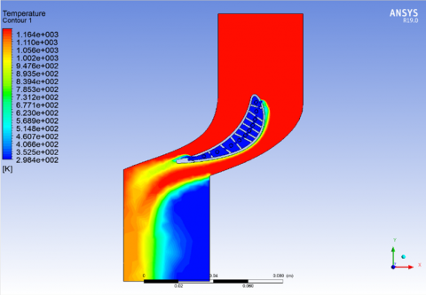
Where it is noted from Figure 5 that the best case for cooling the turbine blade is at pressure 25,000 Pa, as the air was passing through the cooling channel and was consistent with the turbine blade to cool it. To make cooling more efficient, and when pressures increase in other forms, it causes cold air to move away from the turbine blades and causes clogging and reducing the pressure of the incoming air.
(a)
(b)
(c)
(d)
(e)
Figure 5. Temperature contour: (a) 25,000 Pa, (b) 3,0000 Pa, (c) 35,000 Pa, (d) 40,000 Pa, (e) 45,000 Pa
It can be seen in Figure 6 that the higher the air pressure in contact with the surface of the turbine blade. It causes an obstruction in the inlet air pressure, and thus the efficiency of the turbine’s work to generate power decreases. As it needs a stable air pressure to work properly, as the best pressure is 25,000 Pa and does not impede the movement of the inlet air, where this case was based to make a comparison between them and get the most conditions in which it is possible to improve the work of the turbine. The factor associated with optimal stress is the pressure on the blades. When the turbine cooling process is optimal, that is, when the cold airflow applies to the surface of the turbine blades and prevents damage to these blades.
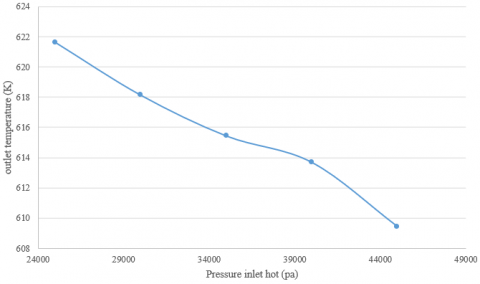
In Figure 7, it is clear that the temperature changes in the exit area with the applied pressure of the blade to cool the outer surface. As it is noticed that the value of the exit temperature increases with the increase in the applied pressure, but at the same time the pressure difference between the entry and exit area increases. This is a negative phenomenon for the turbine as it reduces the mechanical efficiency of the turbine as it was found that the lowest exit temperature at pressure is 45,000 Pa, where temperatures were 609.422 K, which is a good degree as it does not lead to deformation of the turbine and reduce its life.
(a)
(b)
(c)
(d)
(e)
Figure 6. Velocity contour: (a) 25,000 Pa, (b) 30,000 Pa, (c) 35,000 Pa, (d) 40,000 Pa, (e) 45,000 Pa
Figure 7. Temperature gradient with different pressure
The results will be summarized as follows:
The authors would like to thanks Al-Mustaqbal University College for the assistance in completing this work.
[1] Xue, S., Ng, W. (2018). Turbine blade tip external cooling technologies. Aerospace, 5(3): 90. https://doi.org/10.3390/aerospace5030090
[2] Li, L., Wan, H., Gao, W., Tong, F., Li, H. (2019). Reliability based multidisciplinary design optimization of cooling turbine blade considering uncertainty data statistics. Structural and Multidisciplinary Optimization, 59(2): 659-673. https://doi.org/10.1007/s00158-018-2081-5
[3] Krishnaswamy, K., Sivan, S. (2021). Improvement in thermal hydraulic performance by using continuous V and W-shaped rib turbulators in gas turbine blade cooling application. Case Studies in Thermal Engineering, 24: 100857. https://doi.org/10.1016/j.csite.2021.100857
[4] Hosseini Baghdad Abadi, S.M., Zirak, S., Rajabi Zargarabadi, M. (2020). Effect of pulsating injection and mainstream attack angle on film cooling performance of a gas turbine blade. Physics of Fluids, 32(11): 117102. https://doi.org/10.1063/5.0029110
[5] Masci, R., Sciubba, E. (2018). A lumped thermodynamic model of gas turbine blade cooling: Prediction of first-stage blades temperature and cooling flow rates. Journal of Energy Resources Technology, 140(2): 020901. https://doi.org/10.1115/1.4038462
[6] Zhu, X.D., Zhang, J.Z., Tan, X.M. (2019). Numerical assessment of round-to-slot film cooling performances on a turbine blade under engine representative conditions. International Communications in Heat and Mass Transfer, 100: 98-110. https://doi.org/10.1016/j.icheatmasstransfer.2018.12.008
[7] Ziaei-Asl, A., Ramezanlou, M.T. (2019). Thermo-mechanical behavior of gas turbine blade equipped with cooling ducts and protective coating with different thicknesses. International Journal of Mechanical Sciences, 150: 656-664. https://doi.org/10.1016/j.ijmecsci.2018.10.070
[8] Fan, X., Li, L., Zou, J., Zhou, Y. (2019). Cooling methods for gas turbine blade leading edge: Comparative study on impingement cooling, vortex cooling and double vortex cooling. International Communications in Heat and Mass Transfer, 100: 133-145. https://doi.org/10.1016/j.icheatmasstransfer.2018.12.017
[9] Kim, M., Shin, D.H., Kim, J.S., Lee, B.J., Lee, J. (2021). Experimental investigation of effusion and transpiration air cooling for single turbine blade. Applied Thermal Engineering, 182: 116156. https://doi.org/10.1016/j.applthermaleng.2020.116156
[10] Wang, N., Chen, A.F., Zhang, M., Han, J.C. (2018). Turbine blade leading edge cooling with one row of normal or tangential impinging jets. Journal of Heat Transfer, 140(6): V05AT16A007. https://doi.org/10.1115/GT2017-63809
[11] Fan, X., Li, L., Zou, J., Wang, J., Wu, F. (2018). Local heat transfer of vortex cooling with multiple tangential nozzles in a gas turbine blade leading edge cooling passage. International Journal of Heat and Mass Transfer, 126: 377-389. https://doi.org/10.1016/j.ijheatmasstransfer.2018.06.018
[12] Forster, M., Weigand, B. (2021). Experimental and numerical investigation of jet impingement cooling onto a concave leading edge of a generic gas turbine blade. International Journal of Thermal Sciences, 164: 106862. https://doi.org/10.1016/j.ijthermalsci.2021.106862
[13] Biegger, C., Rao, Y., Weigand, B. (2018). Flow and heat transfer measurements in swirl tubes with one and multiple tangential inlet jets for internal gas turbine blade cooling. International Journal of Heat and Fluid Flow, 73: 174-187. https://doi.org/10.1016/j.ijheatfluidflow.2018.07.011
[14] Guo, Z., Song, Z., Fan, J., Yan, X., Huang, D. (2021). Experimental and analytical investigation on service life of film cooling structure for single crystal turbine blade. International Journal of Fatigue, 150: 106318. https://doi.org/10.1016/j.ijfatigue.2021.106318
[15] Wang, X., Xu, H., Wang, J., Song, W., Wang, L. (2021). High pressure turbine blade internal cooling in a realistic rib roughened two-pass channel. International Journal of Heat and Mass Transfer, 170: 121019. https://doi.org/10.1016/j.ijheatmasstransfer.2021.121019
[16] Scalas, A., Yoshida, N. (2018). Multiparty session types, beyond duality. Journal of Logical and Algebraic Methods in Programming, 97: 55-84. https://doi.org/10.1016/j.jlamp.2018.01.001
[17] Wang, L., Wang, S., Wen, F., Zhou, X., Wang, Z. (2018). Effects of continuous wavy ribs on heat transfer and cooling air flow in a square single-pass channel of turbine blade. International Journal of Heat and Mass Transfer, 121: 514-533. https://doi.org/10.1016/j.ijheatmasstransfer.2018.01.004
[18] Yu, Z., Li, C., An, B., Liu, J., Xu, G. (2020). Experimental investigation of film cooling effectiveness on a gas turbine blade pressure surface with diffusion slot holes. Applied Thermal Engineering, 168: 114851. https://doi.org/10.1016/j.applthermaleng.2019.114851
[19] Salpingidou, C., Tsakmakidou, D., Vlahostergios, Z., Misirlis, D., Flouros, M., Yakinthos, K. (2018). Analysis of turbine blade cooling effect on recuperative gas turbines cycles performance. Energy, 164: 1271-1285. https://doi.org/10.1016/j.energy.2018.08.204
[20] Wang, X.S., Cao, F., Zhang, Y., Pan, H.F. (2020). Therapeutic potential of aryl hydrocarbon receptor in autoimmunity. Inflammopharmacology, 28: 63-81. https://doi.org/10.1007/s10787-019-00651-z
[21] Bryant, C.E., Wiese, C.J., Rutledge, J.L., Polanka, M.D. (2019). Experimental evaluations of the relative contributions to overall effectiveness in turbine blade leading edge cooling. Journal of Turbomachinery, 141(4): 041007. https://doi.org/10.1115/1.4041645
[22] Park, S., Kim, J., Bang, M., Moon, H.K., Ueda, O., Cho, H.H. (2021). Effects of seal installation in the mid-passage gap between turbine blade platforms on film cooling. Applied Thermal Engineering, 189: 116683. https://doi.org/10.1016/j.applthermaleng.2021.116683
[23] Chen, D.W., Zhu, H.R., Liu, C.L., Li, H.T., Li, B.R., Zhou, D.E. (2019). Combined effects of unsteady wake and free-stream turbulence on turbine blade film cooling with laid-back fan-shaped holes using PSP technique. International Journal of Heat and Mass Transfer, 133: 382-392. https://doi.org/10.1016/j.ijheatmasstransfer.2018.12.102
[24] Liang, C., Rao, Y., Luo, J., Luo, X. (2021). Experimental and numerical study of turbulent flow and heat transfer in a wedge-Shaped Channel with guiding pin fins for turbine blade trailing edge cooling. International Journal of Heat and Mass Transfer, 178: 121590. https://doi.org/10.1016/j.ijheatmasstransfer.2021.121590
[25] Li, H., Zhou, Z., Xie, G., Xia, S., Tao, Z. (2021). The cooling performance of multiple rows of film holes on the suction surface of a turbine blade under rotating conditions. Applied Thermal Engineering, 188: 116125. https://doi.org/10.1016/j.applthermaleng.2020.116125
[26] Abed, A.M., Majdi, H.S., Hussein, Z., Fadhil, D., Abdulkadhim, A. (2018). Numerical analysis of flow and heat transfer enhancement in a horizontal pipe with P-TT and V-Cut twisted tape. Case Studies in Thermal Engineering, 12: 749-758. https://doi.org/10.1016/j.csite.2018.10.004
[27] Majdi, H.S., Abdulkadhim, A., Abed, A.M. (2019). Numerical investigation of natural convection heat transfer in a parallelogramic enclosure having an inner circular cylinder using liquid nanofluid. Frointers Heat Mass Transf, 12(2): 1-14.
[28] Sun, X., Mohammed, H.I., Tiji, M.E., Mahdi, J.M., Majdi, H.S., Wang, Z., Yaïci, W. (2021). Investigation of heat transfer enhancement in a triple TUBE latent heat storage system using circular fins with inline and staggered arrangements. Nanomaterials, 11(10): 2647. https://doi.org/10.3390/nano11102647
[29] Abdulkadhim, A., Al-Farhany, K., Abed, A.M., Majdi, H.S. (2020). Comprehensive review of natural convection heat transfer in annulus complex enclosures. Al-Qadisiyah Journal for Engineering Sciences, 13(2): 80-90. https://doi.org/10.30772/qjes.v13i2.633
[30] Majdi, H.S., Alabdly, H.A., Hamad, M.F., Hasan, B.O., Hathal, M.M. (2019). Enhancement of heat transfer using aluminum oxide nanofluid on smooth and finned surfaces with COMSOL multiphysics simulation in turbulent flow. Al-Nahrain Journal for Engineering Sciences, 22(1): 44-54. https://doi.org/10.29194/NJES.22010044
[31] Alzamily, A.N., Sultan, A.J., Abdulrahman, A.A., Majdi, H.S. (2022). Study of the impact of tube configurations on the local heat transfer coefficient in mimicked fischer-tropsch bubble column reactor. Processes, 10(5): 976. https://doi.org/10.3390/pr10050976
[32] Majdi, H.S., Abed, A.M., Habeeb, L.J. (2021). Mixed convection heat transfer of cuo-H2o nanofluid in a triangular lid-driven cavity with circular inner body. Journal of Mechanical Engineering Research and Developments, 44(1): 164-175.
[33] Mashkour, M.A., Majdi, H.S., Habeeb, L.J. (2021). Enhancement of forced convection heat transfer in tubes and heat exchangers using passive techniques: A review. Journal of Mechanical Engineering Research and Developments, 44(3): 208-218.
[34] Majdi, H.S., Habeeb, L.J. (2020). Heat transfer for achieving the melting point and super cooling point of phase change materials. Journal of Green Engineering, 10(9): 5886-5901.
[35] Hussein, A., Jary, A.M. (2021). Effect of porous structure on free convection heat transfer from an immersed circular cylinder. Advances in Mechanics, 9(3): 62-80.
[36] Majdi, H.S., Mohammed, A.A., Mohammed, A.A., Habeeb, L.J. (2021). Effect of fibrous porous material on natural convection heat transfer from a horizontal circular cylinder located in a square enclosure. Journal of Thermal Engineering, 7(6): 1468-1478. https://doi.org/10.18186/thermal.990865
[37] Guideline for Technical Regulation Volume 2, Design of Thermal Power Facilities Book 3/12 “Gas Turbine”. (2013). Japan International Cooperation Agency, Socialist Republic of Vietnam, Ministry of Industry and Trade (MOIT).