Alfian Pramudita Putra*![]() | Arief Sofian Hidayat
| Arief Sofian Hidayat![]() | Akif Rahmatillah
| Akif Rahmatillah![]() | Pujiyanto
| Pujiyanto![]() | Khusnul Ain
| Khusnul Ain![]() | I Putu Alit Pawana
| I Putu Alit Pawana![]() | Agrippina Waya Rahmaning Gusti
| Agrippina Waya Rahmaning Gusti![]()
© 2023 IIETA. This article is published by IIETA and is licensed under the CC BY 4.0 license (http://creativecommons.org/licenses/by/4.0/).
OPEN ACCESS
Stroke is the leading cause of physical disabilities worldwide, often resulting in foot drop. Ankle-Foot Orthoses (AFOs) can enhance posture in foot drop cases and augment lower limb stability to support body weight. The Posterior Leaf Spring AFO (PLS AFO), a specific type of AFO, features a narrow retromalleolar region that allows movement without necessitating external force while influencing the AFO's stiffness. This parameter is crucial for determining the mechanical behavior of PLS AFOs. In this study, the impact of the retromalleolar trimline on the stiffness of a 3D PLS AFO model is investigated using the finite element method. Trimline widths of 8 cm and 10 cm, and a thickness of 10 mm, are examined. A 637 N load is applied to the calf area of the 3D PLS AFO model. The results demonstrate that stiffness increases proportionally with retromalleolar trimline width. A PLS AFO configuration with an 8 cm retromalleolar trimline width, 10 mm thickness, and carbon fiber material is deemed suitable for post-stroke foot drop rehabilitation, as it provides improved foot clearance during the swing phase.
ankle foot orthosis, posterior leaf spring ankle foot orthosis, finite element analysis, healthcare, rehabilitation, gait disorder
Stroke is a prevalent pathological condition in the human nervous system, resulting from reduced blood supply to the brain [1]. This reduction leads to damage to brain nerve cells. The World Health Organization (WHO) reported that in 2015, stroke accounted for 11.8% of global deaths, making it the second-largest contributor to mortality after heart disease [2]. According to the 2018 Basic Health Research (Riskesdas) data, the prevalence of stroke in Indonesia was 10.9 per 1,000, an increase of 3.9 compared to Riskesdas 2013.
The majority of worldwide physical disabilities are caused by stroke [3]. A common disability following a stroke is foot drop, which can be attributed to factors such as anterior tibial muscle atrophy or peroneal nerve damage. Foot drop is characterized by an individual's inability to lift their leg or perform dorsiflexion [4, 5]. This condition results in difficulties with walking and necessitates the use of assistive devices to aid in the execution of Activities of Daily Living (ADL) [3]. ADLs include instrumental tasks like shopping and personal tasks such as eating and dressing. Post-stroke patients often require assistance during their first year, with 35% becoming dependent on aid for ADLs [6].
Impairments caused by stroke can manifest in the upper or lower extremities, presenting as pain, muscle weakness, reduced agility, loss of sensation, or coordination problems. Muscle weakness is the primary issue affecting ADL performance in post-stroke patients [7]. This leads to decreased independence in ADLs, which is a critical determinant of quality of life. Post-stroke patients often rely on assistance from their environment to perform ADLs, otherwise experiencing feelings of incapability, social isolation, and abandonment [8]. However, ADL dependence can be managed through the use of assistive devices, which enable limited ADL performance.
Ankle-Foot Orthoses (AFOs) can address foot drop in post-stroke individuals. AFOs help prevent excessive dorsiflexion or complete foot removal, depending on the patient's condition, and improve posture and leg stability to support body weight [9]. AFOs are external aids applied to the foot and differ in type and form. They can be categorized as active (allowing heel movement with external input) or passive (external aids without moving parts) and divided by shape into ventral, dorsal, Posterior Leaf Spring (PLS), Dynamic AFO, and others [10].
The various AFO designs influence their function in the rehabilitation process and are tailored to the patient's condition. AFOs with high rigidity may hinder rehabilitation, prompting the development of designs with varying degrees of rigidity, such as PLS AFOs. PLS AFOs feature a narrow section at the heel, allowing movement without additional external force, as seen in active AFOs [11, 12]. The retromalleolar region's narrowing is a critical factor in AFOs, as it affects their stiffness.
AFO fabrication methods, such as polymer material casting, are often simplistic and rely on trial and error, making them inefficient and costly. Computer-Aided Design (CAD) technology and analysis can assist in AFO fabrication [13]. AFO parameters can be easily modified to suit requirements, and the results can be printed using 3D printing technology. However, further research on PLS AFOs is still needed.
This study aims to design a PLS AFO with varying retromalleolar section widths and analyze the results using Finite Element Analysis (FEA). FEA is a computational analysis method that discretizes 3D models into small elements representing the material's physical properties reacting to applied loads [14]. The outcome displays the forces and pressures acting on the model. Previous research by Mircea (2013) revealed force buildup in the retromalleolar area [15], while Ielapi [16] demonstrated the retromalleolar region's importance in providing room for heel movement in AFO users. FEA can elucidate the mechanical behavior of PLA AFOs under applied loads, simulating natural conditions during use. Furthermore, FEA provides insight into critical aspects of PLS AFOs for designers to consider during the fabrication process.
The anthropometry data of the AFO was obtained from a normal male adult subject with a popliteal height of 27.4 cm, knee height of 33 cm, foot breadth of 11 cm, and a body weight of 65 kg. These data were also in the anthropometric range of the Indonesian population prone to have a stroke, around age of 50-59 [17, 18]. The materials for finite element analysis were Polylactic Acid (PLA), Polypropylene (PP), and Carbon Fiber (CF), as shown in Table 1.
Table 1. Characteristics of polypropylene [13], polylactic acid [19], and carbon fiber [13]
|
Parameters |
PP |
PLA |
CF |
|
Young’s Modulus (GPa) |
2.4 |
3.3 |
70 |
|
Poisson’s ratio |
0.43 |
0.349 |
0.5 |
|
Tensile strength (Mpa) |
30 |
57.8 |
437 |
|
Density (gr/cm3) |
0.9 |
1.25 |
0.902 |
2.1 3D model of PLS AFO
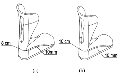
The AFO design used secondary data from subjects on Autodesk Fusion 360. Variations in the AFO included the width of the retromalleolar trimline with values of 8 cm and 10 cm, and the thickness of the AFO was 10 mm. The model is shown in Figure 1. The retromalleolar trimline or foot breadth was taken from male and female Indonesian anthropometric data and the available PLS AFO for foot drop patients [17, 18]. The retromalleolar trimline is where the highest stress was accumulated during gait cycle [20].
2.2 Finite element analysis of PLS AFO 3D model
The 3D solid Posterior Leaf Spring Ankle Foot Orthosis (PLS AFO) model that has been made was analyzed using Finite Element Analysis. The fixed support and loading in the model were set based on the condition during the gait cycle. The load given to the PLS AFO solid 3D model was 637 N which represents the weight of the user applied to the model vertically. Then, this force was applied horizontally to the calf area, showing the forward pulling force when the post-stroke patient walked using the AFO. This force was also used to evaluate the stiffness of the PLS AFO model. By applying the highest force that has the possibility to be experienced, the critical condition of the PLS AFO model could be investigated. This condition also represents a single support gait performed by the PLS AFO’s user. Fixed support is placed on the sole, indicating the state in the stance phase. The mesh size was determined using a convergence study, and it was found that the suitable and converged mesh size was 4.8 mm. After applying the force and fixed support, the analysis was conducted by evaluating the von Mises Stress and Deformation as a contour plot. Figure 2 shows the fixed support and loading position in the PLS AFO model.
Figure 1. AFO model design: (a) Model I (trimline = 8 cm), (b) Model II (trimline = 10 cm)
Figure 2. Boundary condition on AFO model: (a) Cuff loading and (b) Fixed support
2.3 Data analysis
Using PP, PLA, and CF materials, the simulation results were obtained from 2 variations of the AFO model (retromalleolar trimline width variations of 8 cm and 10 cm). The force applied to the AFO is on the calf.
After being given a force, the mechanical behavior of the model that has been loaded will be analyzed, and the value of the Safety Factor and Rotational Stiffness will be calculated. The safety Factor is the security value of the AFO model to find an AFO that is safe and according to the parameters. The safety factor is sought by Equation 1, which calculates the Ultimate Tensile Strength (UTS) value which is the maximum pressure that can be accepted by each material divided by the maximum stress result of each AFO model after simulation [14]. Rotational Stiffness is the moment needed for the AFO to change 10. It is necessary to have an angle value formed from the force applied to the calf to calculate the value of rotational Stiffness. The angle formed is searched with Eq. (2); after that, it is continued to find the value of rotational Stiffness with Eq. (3) [21].
Safety Factor $=\frac{\text { Ultimate Tensile Strength }}{\text { Max von Mises Stress }} \times 100$ (1)
$\theta=\arctan \left(\frac{x}{r}\right)$ (2)
$R o t=\frac{F \cdot r}{\theta}$ (3)
Where, θ=Angle formed based on the initial condition and final displacement (°); Rot=Rotational Stiffness (Nm/°); x=Max Deformation (m); r=AFO length (m); F=Force applied in the cuff (N).
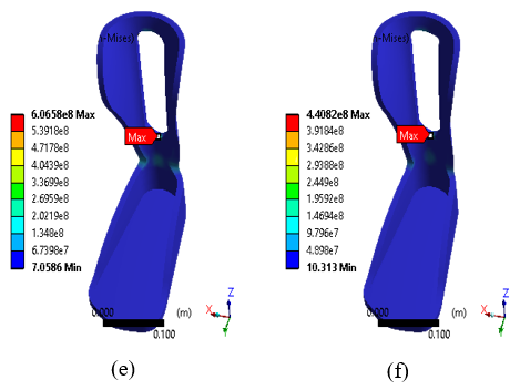
The results of the AFO analysis using FEA are shown in Figure 3 for the von Mises Stress contour plot. Based on variations in the width of the retromalleolar trimline, it shows a decrease in the value of stress and deformation as the width of the retromalleolar trimline increases in the AFO model. This behavior happens with all materials; PP, PLA, and CF. The highest decrease in von Mises Stress was found in the AFO model with CF material from 660 MPa to 406 MPa for 8 and 10 cm retromalleolar trimline, respectively. These results can be seen in Figure 4.
The stress in the retromalleolar trimline showed the stiffness characteristic of the model. It results from the load applied in the cuff section of the model. Thus, the trimline zone is vital in model development. The finite element analysis results showed that peak stresses were always found on the edges of the flexural zone or retromalleolar trimline, particularly at the transitional radii. Consequently, the crack or failure would happen particularly in these sections if the load was applied excessively on the AFO [21, 22]. The highest stress around the retromalleolar trimline was present in all models. This result was suitable with the review of Ielapi et. al. [20]. They mentioned that this area is prone to failure due to fatigue and related to the common clinical aspect. The force produced by the muscle tendons when human walks explain this result.
Figure 3. Contour plot of von Mises Stress (Pa) in PLS AFO model with three materials and two retromalleolar widths: (a) PP with 8 cm; (b) PP with 10 cm; (c) PLA with 8 cm; (d) PLA with 10 cm; (e) CF with 8 cm; and (f) CF with 10 cm
Figure 4. Maximum von Mises Stress of PLS AFO model with three materials and two retromalleolar width
Kerr’s [11] study states that damage to the PLS AFO trimline is common, so a safety factor value is needed to prevent AFO damage. The results of the safety factor value calculation are shown in Figure 5. The 10 cm retromalleolar trimline width variation has a higher safety factor than the 8 cm retromalleolar trimline width variation. This result shows that using a retromalleolar width of 10 cm makes the PLS AFO model safer when a force acts on the model, which in this analysis uses a loading of 637 N. If the AFO is strong enough to withstand the loading, the PLS AFO model is stiff, and the user will have better stability. That is because the model is still not in the fatigue life yet. The application of cyclic loading should be investigated to determine the fatigue behavior of the PLS AFO. However, further studies are needed to investigate the effect of human walking in dynamic conditions on the PLS AFO.
Figure 5. Safety factor of PLS AFO model with three materials and two retromalleolar width
It has long been understood that the materials used and the manufacturing process significantly impact the structural characteristics of orthoses results. To have a greater assurance of the precise qualities of the orthosis, some parameters are production-related elements that need to be carefully managed. This will allow for more precise orthosis manufacture and prescription for each patient’s needs [23]. The AFO model utilized in this investigation was designed based on the available AFO. Conventionally, when the softened sheet is placed over a positive cast, the thermoplastic stretches around the heel of the cast as the flat sheet is molded around the curved heel. This condition is extremely difficult to avoid; however, once the AFO has been produced, the AFO trimlines are adjusted to gain greater control over the resulting AFO properties [23].
Variations in the width of the retromalleolar trimline also resulted in a significant change in the elasticity of the AFO. In contrast, the increase in the width of the retromalleolar trimline resulted in a decrease in the elasticity of the AFO [10]. The elasticity comparison of AFO with 8 cm retromalleolar trimline width variation decreased by about 50% compared to AFO 10 cm retromalleolar trimline width variation in all materials shown in Figure 6. The calculation of the angle and rotational Stiffness of the AFO can be seen in Figures 7 and 8. The decrease in elasticity can be observed from the rotational stiffness value—the higher the rotational stiffness, the lower the resulting angle. When the stiffness is low, the AFO will provide more stability to the user. Especially in the drop foot case, the AFO with higher stiffness will aid foot clearance during the swing phase [19, 23-25].
The choice of material also defines the stiffness properties of the PLS AFO model. Carbon fiber has the highest young’s modulus and tensile strength. Compared to the other two materials, the PLS AFO with carbon fiber had the narrowest angle produced by the cuff loading. The PLS AFO with PP materials and retromalleolar trimline of 8 cm is not recommended based on the rotational angle and stiffness result. It goes beyond the normal angle in the ankle Range of Motion (ROM).
The effect of variations in the width of the retromalleolar trimline focuses on the elasticity of the AFO, where the purpose of the PLS AFO is to provide a Range of Motion (ROM) during the gait cycle supports the motor movement for the rehabilitation of post-stroke drop foot patients. With the availability of ROM, the muscles responsible for foot movement will get stimulation; thus, they can function normally [26]. The normal range of dorsiflexion and plantarflexion angles is 20° [27]. AFO with PLA and CF material is still within the range of dorsiflexion and plantarflexion angles, especially dorsiflexion.
In the normal gait cycle, the loading in the cuff or the dorsal part of the PLS AFO appears during the stance phase, especially in the terminal stance and toe-off. During this subphase, the forefoot rocker is present. The foot rotates with the forefoot as its center. This process starts when the heel or calcaneus is separated from the ground and starts to do plantarflexion, followed by toe-off. The retromalleolar region should maintain the loading during this process while still letting the ankle move in dorsiflexion and plantarflexion in a specific ROM [27].
Figure 6. Contour plot of deformation (m) in PLS AFO model with three materials and two retromalleolar widths: (a) PP with 8 cm; (b) PP with 10 cm; (c) PLA with 8 cm; (d) PLA with 10 cm; (e) CF with 8 cm; and (f) CF with 10 cm
Figure 7. Rotational deformation angle of PLS AFO model with three materials and two retromalleolar width
Figure 8. Rotational stiffness of PLS AFO model with three materials and two retromalleolar width
The variations in the retromalleolar trimline width affect the PLS AFO. The increase in strength is proportional to the increase in retromalleolar trimline width of PLS AFO. The effect of variations in material type parameters can be known by simulations using the same variation of AFO and phase. Based on the analysis results, it can be seen that CF material has better resistance than PP and PLA materials. AFO was considered suitable for poststroke foot drop rehabilitation with a combination of parameters of 8 cm retromalleolar trimline width variation, 10 mm thickness variation, and CF material variation. Combining these parameters results in AFO with high strength and adequate elasticity and is safe to use during the gait phase.
We want to thank the Faculty of Science and Technology, Universitas Airlangga, Indonesia, for the funding under Faculty Excellent Research 2022 with Grant number [No. 1436/UN3.1.8/PT/2022].
[1] Kuriakose, D., Xiao, Z. (2020). Pathophysiology and treatment of stroke: Present status and future perspectives. International Journal of Molecular Sciences, 21(20): 7609. https://doi.org/10.3390/ijms21207609
[2] Benjamin, E.J., Virani, S.S., Callaway, C.W., Chamberlain, A.M., Chang, A.R., Cheng, S., Muntner, P. (2018). Heart disease and stroke statistics—2018 update: A report from the American Heart Association. Circulation, 137(12): e67-e492. https://doi.org/10.1161/CIR.0000000000000558
[3] Alam, M., Choudhury, I.A., Mamat, A.B. (2014). Mechanism and design analysis of articulated ankle foot orthoses for drop-foot. The Scientific World Journal, 2014: 867869. https://doi.org/10.1155/2014/867869
[4] Adil, S., Anwar, T., Al Jumaily, A. (2016). Extreme learning machine based sEMG for drop-foot after stroke detection. In 2016 Sixth International Conference on Information Science and Technology (ICIST), pp. 18-22. IEEE. https://doi.org/10.1109/ICIST.2016.7483378
[5] Feuvrier, F., Sijobert, B., Azevedo, C., Griffiths, K., Alonso, S., Dupeyron, A., Froger, J. (2020). Inertial measurement unit compared to an optical motion capturing system in post-stroke individuals with foot-drop syndrome. Annals of Physical and Rehabilitation Medicine, 63(3): 195-201. https://doi.org/10.1016/j.rehab.2019.03.007
[6] Wurzinger, H.E., Abzhandadze, T., Rafsten, L., Sunnerhagen, K.S. (2021) Dependency in activities of daily living during the first year after stroke. Front. Neurol, 12: 736684. https://doi.org/10.3389/fneur.2021.736684
[7] Whitiana, G.D., Vitriana, V., Cahyani, A. (2017). Level of activity daily living in post stroke patients. Althea Medical Journal, 4(2): 261-266. https://doi.org/10.15850/amj.v4n2.1068
[8] Pei, L., Zang, X.Y., Wang, Y., Chai, Q.W., Wang, J.Y., Sun, C.Y., Zhang, Q. (2016). Factors associated with activities of daily living among the disabled elders with stroke. International Journal of Nursing Sciences, 3(1): 29-34. https://doi.org/10.1016/j.ijnss.2016.01.002
[9] Chen, B., Zi, B., Zeng, Y., Qin, L., Liao, W.H. (2018). Ankle-foot orthoses for rehabilitation and reducing metabolic cost of walking: Possibilities and challenges. Mechatronics, 53: 241-250. https://doi.org/10.1016/j.mechatronics.2018.06.014
[10] Surmen, H.K., Akalan, N.E., Arslan, Y.Z. (2018). Design, Manufacture, and selection of ankle-foot-orthoses, encyclopedia of information science and technology. Fourth Edition, pp. 298-313. https://doi.org/10.4018/978-1-5225-2255-3.ch027
[11] Kerr, E., Moyes, K., Arnold, G., Drew, T. (2011). Permanent deformation of posterior leaf-spring ankle-foot orthoses: A comparison of different materials. JPO: Journal of Prosthetics and Orthotics, 23(3): 144-148. https://doi.org/10.1097/JPO.0b013e3182272941
[12] Bedard, G.G., Motylinski, J., Call, B., Gao, F., Gray, L. (2016). Bench test validation of a dynamic posterior leaf spring ankle-foot orthosis. JPO: Journal of Prosthetics and Orthotics, 28(1): 30-37. https://doi.org/10.1097/JPO.0000000000000081
[13] Zou, D., He, T., Dailey, M., Smith, K.E., Silva, M.J., Sinacore, D.R., Hastings, M.K. (2014). Experimental and computational analysis of composite ankle-foot orthosis. Journal of Rehabilitation Research and Development, 51(10): 1525. https://doi.org/10.1682/JRRD.2014-02-0046
[14] Seshu, P. (2012). Textbook of finite element analysis. PHI Learning Private Limited, New Delhi.
[15] Badescu, M., Purcar, C., Badescu, D. (2013). Ankle foot orthoses with wire insertion. In Applied Mechanics and Materials, 371: 554-558. https://doi.org/10.4028/www.scientific.net/AMM.371.554.
[16] Ielapi, A., Lammens, N., Van Paepegem, W., Forward, M., Deckers, J.P., Vermandel, M., De Beule, M. (2019). A validated computational framework to evaluate the stiffness of 3D printed ankle foot orthoses. Computer Methods in Biomechanics and Biomedical Engineering, 22(8): 880-887. https://doi.org/10.3390/ijms21207609
[17] Chuan, T.K., Hartono, M., Kumar, N. (2010). Anthropometry of the Singaporean and Indonesian populations. International Journal of Industrial Ergonomics, 40(6): 757-766. https://doi.org/10.1016/j.ergon.2010.05.001
[18] Hartono, M. (2018). Indonesian anthropometry update for special populations incorporating Drillis and Contini revisited. International Journal of Industrial Ergonomics, 64: 89-101. https://doi.org/10.1016/j.ergon.2018.01.004
[19] Farbman, D., McCoy, C. (2016). Materials testing of 3D printed ABS and PLA samples to guide mechanical design. In International Manufacturing Science and Engineering Conference, p. V002T01A015. https://doi.org/10.1115/MSEC2016-8668
[20] Ielapi, A., Forward, M., De Beule, M. (2019). Computational and experimental evaluation of the mechanical properties of ankle foot orthoses: A literature review. Prosthetics and Orthotics International, 43(3): 339-348. https://doi.org/10.1177/0309364618824452
[21] Zamanian, H. (2018). Toward creating normal ankle joint behavior for drop foot patients using an ankle foot orthosis (AFO) with superplastic NiTi springs. The University of Toledo.
[22] Chen, R.K., Chen, L., Tai, B.L., Wang, Y., Shih, A.J., Wensman, J. (2014). Additive manufacturing of personalized ankle-foot orthosis. Proceedings of transactions of the North American manufacturing research institution of SME (NAMRC42), 42.
[23] Ramsey, J.A. (2011). Development of a method for fabricating polypropylene non-articulated dorsiflexion assist ankle foot orthoses with predetermined stiffness. Prosthetics and Orthotics International, 35(1): 54-69. https://doi.org/10.1177/0309364610394477
[24] Choo, Y.J., Chang, M.C. (2021). Commonly used types and recent development of ankle-foot orthosis: A narrative review. In Healthcare, 9(8): 1046. https://doi.org/10.3390/healthcare9081046
[25] Putra, A.P., Rahmatillah, A., Rodhiyah, N.K., Pujiyanto, Pawana, I.P.A. (2022). Computational analysis of ankle-foot orthosis for foot drop case during stance phase in gait cycle. Journal of Engineering Science and Technology, 17: 985-996.
[26] Putra, A.P., Hidayat, A.S., Rahmatillah, A., Pujiyanto, Cyberputri, D., Pawana, I.P.A. (2022) Finite element analysis of posterior leaf spring ankle-foot orthosis for tibialis anterior atrophy case. The 3rd International Conference on Physical Instrumentation and Advanced Materials (ICPIAM), p. 030003. https://doi.org/10.1063/5.0108169
[27] Brockett, C.L., Chapman, G.J. (2016). Biomechanics of the ankle. Orthop Trauma, 30(3): 232-238. https://doi.org/10.1016/j.mporth.2016.04.015