Imran Ahmad Khan*![]() | Maseera Shahid
| Maseera Shahid![]() | Jaishanker Prasad Keshari
| Jaishanker Prasad Keshari![]() | Amrita Rai
| Amrita Rai![]()
(This article is part of the Special Issue Technology Innovations and AI Technology in Healthcare)
© 2023 IIETA. This article is published by IIETA and is licensed under the CC BY 4.0 license (http://creativecommons.org/licenses/by/4.0/).
OPEN ACCESS
Error-free communication is crucial for modern electronic devices. Error detection and correction mechanisms are essential to ensure accurate information transmission. With the increasing usage of mobile devices and integrated circuits operating at higher speeds, energy efficiency has become an important design consideration. This study presents carbon nanotube field-effect transistor (CNTFET)-based Hamming Error Detection and Correction circuits and compares them with complementary metal-oxide semiconductor (CMOS)-based counterparts in terms of power efficiency and delay. CNTFETs are more power-efficient and faster than CMOS transistors, making them ideal building blocks for logic circuits. The proposed circuits were simulated using HSPICE. Compared with CMOS circuits, the CNTFET designs consumed less power, had lower delays, and smaller power-delay products. The proposed error detection and correction circuits are suitable for power-efficient and portable systems.
data transmission, power density, faster rate, carbon nano-tubes, parity, nano-scaled device
Data transmission involves sending information from one location to another. While copper wires were traditionally used, wireless networks have largely replaced them [1]. Higher data transfer rates increase the likelihood of errors arising from noise, crosstalk, electromagnetic interference, and other factors. Detecting and correcting these errors is critical to ensure the intended message is received accurately [2]. Error detection adds redundant bits to the transmitted data. A simple and widely used error detection and correction method is the Hamming Code, which employs exclusive-OR logic [3]. Although Hamming codes can detect certain errors, they can only correct one [4, 5].
Modern processors require faster speeds, smaller sizes, and lower power consumption [6]. Reducing transistor size improves performance but also increases power density. Challenges in scaling down complementary metal-oxide semiconductor (CMOS) transistors have been increasing [7-9]. Carbon nanotube field-effect transistors (CNTFETs) are nanoscale devices with high performance and low power consumption [10]. CNTFETs use carbon nanotubes (CNTs) instead of bulk silicon in the channel. Compared with CMOS, CNTs provide higher carrier mobility, enabling faster operation. While early CNTFETs were p-type due to contact doping, n-type CNTFETs were subsequently developed through alkali gas doping and thermal annealing in vacuum. Both p-type and n-type CNTFETs can now be fabricated. CNTFETs and MOSFETs have similar structures, but CNTFETs are suitable for nanoscale devices [11].
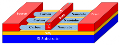
Figure 1 shows a CNTFET schematic with single-walled CNTs sandwiched between two electrodes. Highly doped CNTs are placed between the gate and source/drain electrodes. Undoped CNTs under the gate electrode form the channel [6, 11].
Figure 1. Schematic of CNTFET [2]
CNTFET gate width can be obtained from equation [2]:
$\mathrm{W}_{\text {gate }} \approx \operatorname{Max}\left(\mathrm{W}_{\min }, \mathrm{M} X \mathrm{P}\right)$ (1)
CNT diameter can be calculated from Eq. (2) [6]:
$\mathrm{D}_{\mathrm{CNT}}=\frac{\sqrt{3} a_0}{\pi} \sqrt{n^2+m^2+n m}$ (2)
where,
a0=142 pm=the distance in between adjacent carbon atoms;
m and n are chirality vectors which show the roll orientation of carbon Nano-tubes.
Now, the Eq. (2) can be written as,
$\mathrm{D}_{\mathrm{CNT}}=0.0783 \sqrt{n^2+m^2+n m}$ (3)
Carbon nanotubes (CNTs) are a novel material, and CNT field-effect transistors (CNTFETs) are the associated devices that can potentially replace CMOS FETs and enable scalability below 22 nm [12]. In fact, CNTFETs are a promising alternative to silicon transistors for high performance and low power consumption [13-15].
Plastic waste is a major environmental problem, generating over 500,000 tons per year. It poses dangers to human and animal health, especially for seabirds that cannot digest it, often leading to death. Polypropylene (PP) plastics account for 19% of this waste and have a high carbon content (86.7%) compared with other plastics like high-density polyethylene, low-density polyethylene, and polyethylene terephthalate. This carbon-rich PP waste is useful for generating CNTs [16].
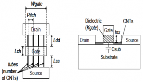
CNTFETs can extend the validity of Moore's law [17]. Various digital and analog circuits and systems based on CNTFETs have been proposed, such as adders [18-21], flip-flops [22-25], and multiplexers [26-28]. CNTFETs resemble MOSFETs but replace the bulk silicon channel with semiconducting CNTs, as shown in Figure 2.
Figure 2. Schematic CNT-FET cross section [12, 29]
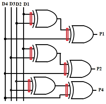
Figure 3. Codeword generation
Various error detecting circuits have been discussed in past [30-33], the most common method is the Hamming Error Detection. R. W. Hamming is the inventor of this approach. Errors are not only detected but also corrected using Hamming codes. This method can detect and also capable to correct errors of two bit at the same time [3, 34]. While simple parity method cannot fix errors and can only discover odd number of them. R. W. Hamming introduced the (7, 4) coding in 1950. This method converts four data bits to seven after addition of three parity bits. Single-bit errors can be detected and corrected using Hamming (7, 4). It can identify (but not correct) double-bit errors with the inclusion of an overall parity bit [35]. Data bits along with parity bits are used to create a codeword. More than one parity bit is used in this and these are placed at certain positions of power of 2 [3]. Figure 3 represents the proposed CNT based circuit of Hamming Codeword Generation.
Number of parity bits is decided by below equation:
$2^P \geq \mathrm{n}+\mathrm{P}+1$
where,
n=No. of Data Bits;
P=No. of Parity Bits.
Converting the parity bit value in to decimal equivalent detects error [6]. There is no error if Codeword contains solely 0's.
Let Data Bits=1011
No. of parity bits:
2P>=n+P+1;
Let p=3;
23>=4+3+1;
8>=8;
So, P=3.
Position of parity bits:
Position of the first parity bit=1 (2°);
Position of the second parity bit=2 (21);
Position of the third parity bit=4 (22).
7 Bit Codeword will be: D4 D3 D2 P4 D1 P2 P1.
There are 4 data bits and 3 parity bits in this example. As a result, it will be known as the (7, 4) Hamming Code [35].
Calculation of P1
P1=Ex-OR(D1, D2, D4)=Ex-OR (1, 0, 1)
P1=0
Calculation of P2
P2=Ex-OR (D1, D3, D4)=Ex-OR (1, 1, 1)
P2=1
Calculation of P4
P4=Ex-OR (D2, D3, D4)=Ex-OR (0, 1, 1)
P4=0
Decimal equivalent of 010 (P4 P2 P1)=2, Error is found at Second bit.
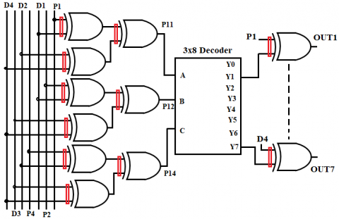
Figure 4 represents the proposed CNT based Hamming Error Correcting Circuit. For Error Correction by Hamming Code, we are using 3X8 Decoder. Table 1 shows Input Combinations and Output of the Decoder.
Let Inputs of Decoder are: P11, P12 & P14.
Calculation of P11
P11=Ex-OR (P1, D1, D2, D4)=Ex-OR (0, 1, 0, 1)=0
Calculation of P12
P12=Ex-OR (P2, D1, D3, D4)=Ex-OR (1, 1, 1, 1)=0
Calculation of P14
P14=Ex-OR (P4, D2, D3, D4)=Ex-OR (0, 0, 1, 1)=0
Let Corrected Codeword is: OUT7 OUT6 OUT5 OUT4 OUT3 OUT2 OUT1.
where,
OUT7=Ex-OR (Y7, D4);
OUT6=Ex-OR (Y6, D3);
OUT5=Ex-OR (Y5, D2);
OUT4=Ex-OR (Y4, P4);
OUT3=Ex-OR (Y3, D1);
OUT2=Ex-OR (Y2, P2);
OUT1=Ex-OR (Y1, P1).
Table 1. Input combinations and output of decoder
|
Inputs of decoder |
Output of decoder |
||
|
P14 |
P12 |
P11 |
|
|
Logic 0 |
Logic 0 |
Logic 0 |
Y0 |
|
Logic 0 |
Logic 0 |
Logic 1 |
Y1 |
|
Logic 0 |
Logic 1 |
Logic 0 |
Y2 |
|
Logic 0 |
Logic 1 |
Logic 1 |
Y3 |
|
Logic 1 |
Logic 0 |
Logic 0 |
Y4 |
|
Logic 1 |
Logic 0 |
Logic 1 |
Y5 |
|
Logic 1 |
Logic 1 |
Logic 0 |
Y6 |
|
Logic 1 |
Logic 1 |
Logic 1 |
Y7 |
Figure 4. Hamming Error Correcting Circuit
4.1 Hamming Error Detection
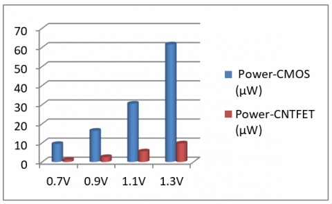
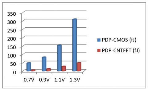
When the input voltage is varied from 0.7V to 1.3V, Table 2 illustrates the Delay and Average Power Consumption using CMOS and CNTFET while Table 3 represents power-delay-product. The tables demonstrates that the delay with proposed CNTFET is shorter than the delay with CMOS, and that the power consumption with proposed CNTFET is less than the power consumption with CMOS. In addition, the power delay product of CNTFET is lower than that of CMOS.
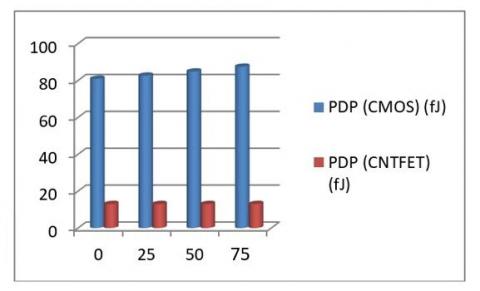
When the temperature is varied from 0℃ to 75℃, Table 4 illustrates the Delay and Average Power Consumption using CMOS and CNTFET while Table 5 represents power-delay-product. The tables demonstrates that the delay in proposed CNTFET is smaller than the delay in CMOS, and that the power consumption in CNTFET is likewise much lower than the power consumption in CMOS. In addition, while comparing CNTFET with CMOS, it can be shown that the power delay product is lower in proposed CNTFET. Average Power Comparison on Different Input Voltages and on different temperatures of Hamming Error Detection are represented by Figure 5 and Figure 6 respectively. Figure 7 and Figure 8 represents PDP as a function of supply voltage and temperature of Hamming Error Detection respectively.
Table 2. Delay and average power comparison on input voltage variation when temp=25℃
|
Input voltage (V) |
Delay (CMOS) (nS) |
Delay (CNTFET) (nS) |
Average power (CMOS) (µW) |
Average power (CNTFET) (µW) |
|
0.7 |
5.0792 |
5.0017 |
9.44 |
1.14 |
|
0.9 |
5.0446 |
5.0082 |
16.38 |
2.60 |
|
1.1 |
5.0337 |
5.0089 |
30.56 |
5.56 |
|
1.3 |
5.0277 |
5.0092 |
61.59 |
9.74 |
Table 3. Power delay product on input voltage variation when temp=25℃
|
Input Voltage (V) |
PDP (CMOS) (fJ) |
PDP (CNTFET) (fJ) |
|
0.7 |
47.94 |
5.736 |
|
0.9 |
82.66 |
13.02 |
|
1.1 |
153.8 |
27.85 |
|
1.3 |
309.67 |
48.83 |
Table 4. Delay and average power comparison on temperature variation when input voltage=0.9V
|
Temp. (℃) |
Delay (CMOS) (nS) |
Delay (CNTFET) (nS) |
Average power (CMOS) (µW) |
Average power (CNTFET) (µW) |
|
0 |
5.04 |
5.01 |
16.06 |
2.601 |
|
25 |
5.04 |
5.01 |
16.38 |
2.601 |
|
50 |
5.05 |
5.01 |
16.80 |
2.601 |
|
75 |
5.057 |
5.01 |
17.30 |
2.601 |
Table 5. Power delay product on temperature variation when input voltage=0.9V
|
Temperature (℃) |
PDP (CMOS) (fJ) |
PDP (CNTFET) (fJ) |
|
0 |
80.94 |
13.02 |
|
25 |
82.66 |
13.02 |
|
50 |
84.89 |
13.02 |
|
75 |
87.49 |
13.02 |
Figure 5. Average power comparison on different input voltages of Hamming Error Detection
Figure 6. Average power comparison on different temperatures of Hamming Error Detection
Figure 7. PDP vs. supply voltage (V) of Hamming Error Detection
Figure 8. PDP vs. temperature (℃) of Hamming Error Detection
4.2 Hamming Error Correction
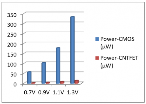
When the input voltage is varied from 0.7V to 1.3V, Table 6 illustrates the Delay and Average Power Consumption using CMOS and CNTFET while Table 7 represents power-delay-product. The tables demonstrates that the delay with CNTFET is shorter than the delay with CMOS, and that the power consumption with CNTFET is less than the power consumption with CMOS. In addition, the power delay product of CNTFET is lower than that of CMOS.
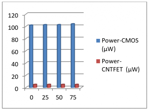
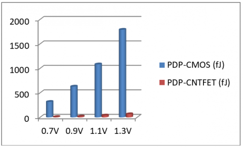
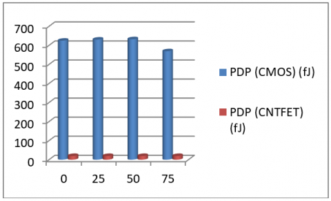
When the temperature is varied from 0℃ to 75℃, Table 8 illustrates the Delay and Average Power Consumption using CMOS and CNTFET while Table 9 represents power-delay-product. The tables demonstrates that the delay in CNTFET is smaller than the delay in CMOS, and that the power consumption in CNTFET is likewise much lower than the power consumption in CMOS. In addition, while comparing CNTFET with CMOS, it can be shown that the power delay product is lower in CNTFET. Average Power Comparison on Different Input Voltages and on different temperatures of Hamming Error Correction are represented by Figure 9 and Figure 10 respectively. Figure 11 and Figure 12 represents PDP as a function of supply voltage and temperature of Hamming Error Correction respectively.
Table 6. Delay and average power comparison on input voltage variation when temp=25℃
|
Input voltage (V) |
Delay (CMOS) (nS) |
Delay (CNTFET) (nS) |
Average power (CMOS) (µW) |
Average power (CNTFET) (µW) |
|
0.7 |
5.531 |
3.623 |
57.41 |
2.62 |
|
0.9 |
6.136 |
3.764 |
102.74 |
5.209 |
|
1.1 |
6.109 |
4.304 |
177.46 |
9.258 |
|
1.3 |
5.376 |
4.435 |
333.23 |
14.99 |
Table 7. Power delay product on input voltage variation when temperature=25℃
|
Input voltage (V) |
PDP (CMOS) (fJ) |
PDP (CNTFET) (fJ) |
|
0.7 |
317.58 |
9.49 |
|
0.9 |
630.50 |
19.60 |
|
1.1 |
1084.13 |
39.85 |
|
1.3 |
1791.47 |
66.52 |
Table 8. Delay and average power comparison on temperature variation when input voltage=0.9V
|
Temperature (℃) |
Delay (CMOS) (nS) |
Delay (CNTFET) (nS) |
Average Power (CMOS) (µW) |
Average Power (CNTFET) (µW) |
|
0 |
6.1246 |
3.7644 |
102.02 |
5.2092 |
|
25 |
6.1369 |
3.7644 |
102.74 |
5.2092 |
|
50 |
6.1498 |
3.7644 |
102.83 |
5.2092 |
|
75 |
5.4655 |
3.7644 |
104.17 |
5.2092 |
Table 9. Power delay product on temperature variation when input voltage=0.9V
|
Temperature (℃) |
PDP (CMOS) (fJ) |
PDP (CNTFET) (fJ) |
|
0 |
624.83 |
19.609 |
|
25 |
630.505 |
19.609 |
|
50 |
632.38 |
19.609 |
|
75 |
569.34 |
19.609 |
Figure 9. Average power comparison on different input voltages of Hamming Error Correction
Figure 10. Average power comparison on different temperatures of Hamming Error Correction
Figure 11. PDP vs. supply voltage (V) of Hamming Error Correction
Figure 12. PDP vs. temperature (℃) of Hamming Error Correction
For error-free communication, Hamming Error Detecting and Correcting Circuits are commonly employed. In this paper, CNTFET-based Hamming Error Detection and Correction circuits are presented. CNTFET is favoured over CMOS for a variety of reasons, including low power consumption and increased speed. The Hamming Error Detecting and Correcting circuit was simulated using HSPICE. According to comparative charts of typical power consumption utilising CMOS and CNTFET, CNTFET consumes significantly less power than CMOS. The results also show that the delay in the case of CNTFET is shorter than that of CMOS, and that the power delay product for CNTFET is likewise lower than that of CMOS. Therefore, Hamming Error Detecting and Correcting Circuits are suitable for Power Efficient and Portable Systems.
[1] Williams, B.R., Chuvakin, A.A. Milroy, D. (2015). Chapter 8-using wireless networking. PCI Compliance (Fourth Edition),Understand and Implement Effective PCI Data Security Standard Compliance, 141-159. https://doi.org/10.1016/B978-0-12-801579-7.00008-X
[2] Moaiyeri, M.H., Mirzaee, R.F., Doostaregan, A., Navi, K., Hashemipour, O. (2013). A universal method for designing low‐power carbon nanotube FET‐based multiple‐valued logic circuits. IET Computers & Digital Techniques, 7(4): 167-181. https://doi.org/10.1049/iet-cdt.2013.0023
[3] Fauzi, A., Nurhayati, Rahim, R. (2017). Bit error detection and correction with hamming code algorithm. International Journal of Scientific Research in Science, Engineering and Technology (IJSRSET), 3(1): 76-81.
[4] Mokara, D., Naidu, S., Gupta, A.K. (2017). Design and implementation of hamming code using VHDL & DSCH. International Journal of Latest Engineering Research and Applications (IJLERA), 2(11), 33-40.
[5] Ritambhara, Sharma, Y., Agarwal, N., Vyas, S. (2020). A study on carbon nano-tube field effect transistor (CNTFETs): A promising technology for future ICs. International Journal of Scientific & Engineering Research, 11(9): 4-8.
[6] Samadi, H., Shahhoseini, A., Aghaei-liavali, F. (2017). A new method on designing and simulating CNTFET_based ternary gates and arithmetic circuits. Microelectronics Journal, 63: 41-48. https://doi.org/10.1016/j.mejo.2017.02.018
[7] Khan, I.A., Beg, M.T. (2014). Clock gated single-edge-triggered flip-flop design with improved power for low data activity applications. International Journal on Electrical Engineering and Informatics, 6(3): 562-576. https://doi.org/10.15676/ijeei.2014.6.3.9
[8] Zhang, R.M., Walus, K., Wang, W., Jullien, G.A. (2004). A method of majority logic reduction for quantum cellular automata. In IEEE Transactions on Nanotechnology, 3(4): 443-450. https://doi.org/10.1109/TNANO.2004.834177
[9] Khan, I.A., Beg, M.T. (2019). Power efficient design of semi-dynamic master-slave single-edge-triggered flip-flop. International Journal on Electrical Engineering and Informatics, 11(2): 252-262. https://doi.org/10.15676/ijeei.2019.11.2.2
[10] Hills, G., Bardon, M.G., Doornbos, G., Yakimets, D., Schuddinck, P., Baert, R., Jang, D., Mattii, L., Sherazi, S.M.Y., Rodopoulos, D., Ritzenthaler, R., Lee, C., Thean, A.V., Radu, I., Spessot, A., Debacker, P., Catthoor, F., Raghavan, P., Shulaker, M.M., Wong, H.S.P., Mitra, S. (2018). Understanding energy efficiency benefits of carbon nanotube field-effect transistors for digital VLSI. In IEEE Transactions on Nanotechnology, 17(6): 1259-1269. https://doi.org/10.1109/TNANO.2018.2871841
[11] Zahoor, F., Hussin, F.A., Khanday, F.A., Ahmad, M.R., Mohd Nawi, I., Ooi, C.Y., Rokhani, F.Z. (2021). Carbon nanotube field effect transistor (CNTFET) and resistive random access memory (RRAM) based ternary combinational logic circuits. Electronics. 10(1): 79. https://doi.org/10.3390/electronics10010079
[12] Kim, Y.B. (2011). Integrated circuit design based on carbon nanotube field effect transistor. Transactions on Electrical and Electronic Materials, 12(5): 175-188. https://doi.org/10.4313/TEEM.2011.12.5.175
[13] Hu, Z.Y., Tulevski, G.S., Hannon, J.B., Afzali, A., Liehr, M., Park, H. (2015). Variability and reliability analysis in self-assembled multichannel carbon nanotube field-effect transistors. Applied Physics Letters, 106(24): 243106. https://doi.org/10.1063/1.4922770
[14] Prakash, P., Sundaram, K.M., Bennet, M.A. (2018). A review on carbon nanotube field effect transistors (CNTFETs) for ultra-low power applications. Renewable and Sustainable Energy Reviews, 89: 194-203. https://doi.org/10.1016/j.rser.2018.03.021
[15] Obite, F., Ijeomah, G., Bassi, J.S. (2019). Carbon nanotube field effect transistors: toward future nanoscale electronics. International Journal of Computers and Applications, 41(2): 149-164. https://doi.org/10.1080/1206212X.2017.1415111
[16] Wulan, P.P.D.K., Ningtyas J.A. Hasanah, M. (2019). The effect of nickel coating on stainless steel 316 on growth of carbon nanotube from polypropylene waste. Evergreen, 6(1): 98-102. https://doi.org/10.5109/2328411
[17] Wu, J., Shen, Y.L., Reinhardt, K., Szu H., Dong, B.Q. (2013). A nanotechnology enhancement to moore’s law. Applied Computational Intelligence and Soft Computing, 2013(1): 1-13. https://doi.org/10.1155/2013/426962
[18] Merlin, J.L., Khan, T.E.A., Hameed, T.A.S. (2020). Design of a low power three bit ternary prefix adder using CNTFET technology. In AIP Conference Proceedings, AIP Publishing LLC, 2222(1): 020005. https://doi.org/10.1063/5.0003994
[19] Zarandi, A.D., Reshadinezhad, M.R., Rubio, A. (2020). A systematic method to design efficient ternary high performance CNTFET-based logic cells. IEEE Access, 8: 58585-58593. https://doi.org/10.1109/ACCESS.2020.2982738
[20] Ebrahimi, S.A., Reshadinezhad, M.R., Bohlooli, A., Shahsavari, M. (2016). Efficient CNTFET-based design of quaternary logic gates and arithmetic circuits. Microelectronics Journal, 53: 156-166. https://doi.org/10.1016/j.mejo.2016.04.016
[21] Khan, I.A. (2022). Design and implementation of carbon nano-tube based full adder at 32nm technology for high speed and power efficient arithmetic applications. In Journal of Physics: Conference Series, IOP Publishing, 2161(1): 012050. https://doi.org/10.1088/1742-6596/2161/1/012050
[22] Badugu, D.M., Sunithamani, S., Shaik, J.B., Vobulapuram, R.K. (2020). Design of hardened flip-flop using schmitt trigger-based SEM latch in CNTFET technology. Circuit World, 47(1): 51-59. https://doi.org/10.1108/CW-10-2019-0141
[23] Karimi, A., Rezai, A., Hajhashemkhani, M.M. (2019). Ultra-low power pulse-triggered CNTFET-based flip-flop. In IEEE Transactions on Nanotechnology, 18: 756-761. https://doi.org/10.1109/TNANO.2019.2929233
[24] Shaveisi, M., Rezaei, A. (2018). Performance analysis of reversible sequential circuits based on carbon nanotube field effect transistors (CNTFETs). Journal of Electrical and Computer Engineering Innovations (JECEI), 6(2): 173-183. https://doi.org/10.22061/jecei.2019.5015.183
[25] Swami, K., Sharma, R. (2023). Implementation and optimization of CNTFET based ultra-low energy delay flip flop designs: Design, simulation and performance investigation. Silicon, 15(2): 1027-1035. https://doi.org/10.1007/s12633-021-01085-5
[26] Garg, S., Gupta, T.K., Pandey, A.K. (2020). A 4: 1 multiplexer using dual chirality cntfet-based domino logic in nano-scale technology. International Journal of Electronics, 107(4): 513-541. https://doi.org/10.1080/00207217.2019.1663942
[27] Shalamzari, Z.D., Zarandi, A.D., Reshadinezhad, M.R. (2020). Newly multiplexer-based quaternary half-adder and multiplier using CNTFETs. AEU-International Journal of Electronics and Communications, 117: 153128. https://doi.org/10.1016/j.aeue.2020.153128
[28] Rahmati, S., Farshidi, E., Ganji, J. (2020). A novel method design multiplexer quaternary with CNTFET. Journal of Electrical and Computer Engineering Innovations (JECEI), 8(1): 9-18. https://doi.org/10.22061/jecei.2020.7091.356
[29] Biswas, S., Kundu, P., Kabir, H., Islam, M., Ahmed, S., Aditi, N.I. (2015). Carbon nanotube field effect transistors based low THD and noise-immune double stage differential amplifier for nanoelectronics. GSTF Journal of Engineering Technology (JET), 3: 1-9. https://doi.org/10.7603/s40707-014-0006-2
[30] Khan, I.A., Mahmood, M.R. (2022). Design and analysis of power-efficient carbon nanotube-based parity checker circuits for high-data transmission rate. In Innovations in Electronics and Communication Engineering: Proceedings of the 9th ICIECE 2021, Singapore: Springer Singapore, 597-603. https://doi.org/10.1007/978-981-16-8512-5_63
[31] Singh, V., Sharma, N. (2015). A review on various error detection and correction methods used in communication. American International Journal of Research in Science, Technology, Engineering & Mathematics, 9(3): 252-257.
[32] Kumar, D., Kumar, C., Gautam, S., Mitra, D. (2017). Design of practical parity generator and parity checker circuits in QCA. In 2017 IEEE International Symposium on Nanoelectronic and Information Systems (iNIS), IEEE, 28-33. https://doi.org/10.1109/iNIS.2017.16
[33] Khan, I.A., Mahmood, M.R., Keshari, J.P., Tariq Beg, M. (2022). Design of low-power cntfet parity generators for high-speed data transmission. In Innovations in Electronics and Communication Engineering: Proceedings of the 9th ICIECE 2021, Singapore: Springer Singapore, 605-611. https://doi.org/10.1007/978-981-16-8512-5_64
[34] Saleh, A.H. (2015). Design of hamming code for 64 bit single error detection and correction using VHDL. Diyala Journal of Engineering Sciences, 8(3): 22-37. https://doi.org/10.24237/djes.2015.08305
[35] Singh, A.K. (2016). Error detection and correction by hamming code. In 2016 International Conference on Global Trends in Signal Processing, Information Computing and Communication (ICGTSPICC), IEEE, 35-37. https://doi.org/10.1109/ICGTSPICC.2016.7955265