Mohsin N. Hamzah*![]() | Ammar S. Merza
| Ammar S. Merza![]()
© 2023 IIETA. This article is published by IIETA and is licensed under the CC BY 4.0 license (http://creativecommons.org/licenses/by/4.0/).
OPEN ACCESS
In spur gears, the maximum bending stress concentration is known to occur in the gear tooth fillet region. This study focuses on the geometric optimization of symmetric involute gears to alleviate stress concentrations near the fillet. Stress relief is achieved by incorporating strategically placed holes and semi-circular cuts in the area between adjacent teeth. The size and location of these features are varied to reduce bending stresses, leading to increased load capacity, extended gear lifetime, reduced manufacturing costs, and minimized noise and vibration. Finite element methods are employed to formulate and model spur gears, followed by a geometric optimization process to achieve the desired stress distribution. Two-dimensional modeling is utilized based on gear engagement theories, taking advantage of ANSYS Mechanical APDL 2020 R1 and optimization tools. The gear geometry is modified to redistribute stress in high-stress regions, optimizing the power transmission capacity and reducing costs. The current finite element formulation is validated through numerical examples and by comparing the results with those obtained from ANSYS. The optimization process results in a 25% reduction in stress concentration, enhancing the gear's load-carrying capacity.
gears, geometric optimization, root stress, stress relief, symmetric teeth
The primary objective of gear design is the optimal transmission of power while minimizing dimensions, noise, vibration, and manufacturing costs. A growing demand for higher load-carrying capacities necessitates compact transmission systems, creating challenges in stress concentration within specific regions. This limits the selection of materials for gear manufacturing. By optimizing the geometric features of gears to reduce dimensions, significant cost reductions can be achieved. Numerical methods, particularly Finite Element Methods (FEM), offer powerful tools for analyzing and optimizing gear geometry. Due to the symmetry, positive definiteness, and sparseness of the resulting system of equations in FEM, efficient solvers can be employed [1, 2]. An alternative to FEM is the boundary element method [3].
Historically, efforts have primarily focused on improving gear geometry, especially the working involute flanks. These have been technically classified and described by various standard accuracy grades based on application type and tolerance limits, such as profile, runout, lead, and pitch variation. The maximum bending stress concentration is known to occur at the gear tooth fillet [4]. However, its profile and accuracy are typically determined by a drawing with a generous root diameter tolerance and, in some cases, the minimum fillet radius, which can be difficult to assess. Improvement in tooth bending strength is typically achieved through gear technology rather than gear geometry.
Two main approaches have been employed to reduce bending stress for a given tooth size. The first involves altering the generating cutter tooth tip, with the most common application being the use of a rack with a full tip radius [4]. The second approach modifies the gear tooth fillet profile from the trochoidal to the circular fillet. Further enhancements for both methods have been based on mathematical function-fitting techniques, where the cutter tip radius or the gear tooth trochoid fillet profile is replaced by a parabola, ellipse, chain curve, or another curve to minimize bending stress [5].
Numerous studies have been conducted to investigate gear tooth stresses. Fredette and Brown [6] examined the drilling of holes across the entire tooth to determine the overall effect of hole size and location on critical stresses in the gear. Spitas et al. [7] considered a circular root fillet for spur gears and investigated it numerically using the boundary element method (BEM). They compared the strength of the teeth with the standard design by discretizing the tooth boundary using isoparametric boundary elements, demonstrating that the circular design outperforms the existing trochoidal design in terms of fatigue endurance without affecting pitting resistance. Similar research using various techniques and methodologies for improving fillet strength in conventionally designed symmetric and asymmetric spur and helical gears has been conducted by other researchers [8-11]. Gear optimization is another area that has attracted significant attention [12-17].
To design the tooth profile, Zou et al. [18, 19] proposed using a nonparametric cubic spline. Schneider et al. [20] employed a Bezier curve to design the tooth profile. Math and Chand [21] investigated four different hob tip contours to improve the transition between the spur gear root and the involute tooth profile. Pedersen [22] optimized the hob tip contour using a distorted super-elliptical curve, which reduced tooth root stress by up to 14.4%. Zhao [23] achieved an 11.8% reduction in tooth root stress by describing the cutter tip of a hob using a quadratic rational Bezier curve. Uelpenich and Tenberge [24] optimized hob contours with a Bezier curve and proposed an analytical equation to shorten the optimization time. However, they did not provide a detailed definition for a hob's tip contour. Dong et al. [25] optimized standard hob contours with a Bezier curve to reduce tooth root stress using a genetic algorithm and FEM. The optimization procedure is designed based on the specifications of the components. Different approaches, such as RP methods, Fusion 360, and others, have been used for topology optimization [24-30].
The objective of this research is to achieve an optimal design for symmetric spur gears by reducing high stress concentrations, particularly in the fillet area. The optimization procedure involves using various hole sizes and/or locations to accomplish this goal. Additionally, semi-circular cuts of varying diameters are employed in the region between adjacent teeth. Compared to existing methods [8-10], this approach is a feasible strategy for increasing the gear's load-carrying capacity and/or reducing the amount of material used.
2.1 Finite element formulation
The present analysis is dedicated for analysis spur gear based on the finite element methods. Therefore, our problem is two-dimensional plane stress problem. The strain components of two-dimensional elasticity are:
$\left[\begin{array}{c}\varepsilon_x \\ \varepsilon_y \\ \gamma_{x y}\end{array}\right]=\left[\begin{array}{c}\frac{\partial u}{\partial x} \\ \frac{\partial v}{\partial \mathrm{y}} \\ \frac{\partial u}{\partial \mathrm{y}}+\frac{\partial v}{\partial \mathrm{x}}\end{array}\right]$ (1)
The gears are considered as spur gears, stress-strain relationship for plane stress provides the following:
$\left[\begin{array}{l}\sigma_x \\ \sigma_y \\ \tau_{x y}\end{array}\right]=\frac{E}{\left(1-v^2\right)}\left[\begin{array}{ccc}1 & v & 0 \\ v & 1 & 0 \\ 0 & 0 & 1-v\end{array}\right]\left[\begin{array}{c}\varepsilon_x \\ \varepsilon_y \\ \gamma_{x y}\end{array}\right]$
or in matrix form as:
$\boldsymbol{\sigma}=\mathbf{D} \boldsymbol{\varepsilon}$ (2)
The displacement within the element can be expressed in terms of nodal displacement as:
$\begin{aligned} & u(x, y)=\sum_{i=1}^n u_i \mathcal{N}_i(x, y) \\ & v(x, y)=\sum_{i=1}^n v_i \mathcal{N}_i(x, y)\end{aligned}$
or in terms of local coordinate system as:
$u(\xi, \eta)=\sum_{i=1}^n u_i \mathcal{N}_i(\xi, \eta)$ (3a)
$v(\xi, \eta)=\sum_{i=1}^n v_i \mathcal{N}_i(\xi, \eta)$ (3b)
Eq. (3) can be substituted into Eq. (1) as:
$\boldsymbol{\varepsilon}=\mathbf{B} \boldsymbol{\delta}$ (4)
where, the matrix B represents a strain-displacement transformation of the element, and can be expressed as:
$\mathbf{B}=\left[\begin{array}{ccccc}\frac{\partial \mathcal{N}_1}{\partial x} & 0 & \cdots & \frac{\partial \mathcal{N}_n}{\partial x} & 0 \\ 0 & \frac{\partial \mathcal{N}_1}{\partial y} & \cdots & 0 & \frac{\partial \mathcal{N}_n}{\partial y} \\ \frac{\partial \mathcal{N}_1}{\partial y} & \frac{\partial \mathcal{N}_1}{\partial x} & \cdots & \frac{\partial \mathcal{N}_n}{\partial y} & \frac{\partial \mathcal{N}_n}{\partial x}\end{array}\right]$
Using the principal of minimizing the total potential energy for deriving the element equation, the total potential energy of an elastic body W is define as:
$\chi=U-W$ (5)
where, U is the strain energy defined as, $U=\frac{1}{2} \iiint_V \boldsymbol{\sigma}^T \varepsilon d V$, W is the work done on the body by the external forces, $W=\boldsymbol{\delta}^T \mathbf{F}$. And F is the total equivalent nodal force vector. Apply the principal of minimum total potential energy leads to element equation,
$\left[\iiint_V \mathbf{B}^T \mathbf{D} \mathbf{B} d V\right] \boldsymbol{\delta}=\mathbf{F}$
in matrix form,
$\mathbf{K} \boldsymbol{\delta}=\mathbf{F}$ (6)
where, $\mathbf{K}$ is the element stiffness matrix defined as:
$\mathbf{K}=\left[\iiint_V \mathbf{B}^T \mathbf{D} \mathbf{B} d V\right]$ (7)
2.2 Generating involute profiles
The tooth profiles of the involute gear can be generated using involute profile, which is a short segment involute curve scaled to match the base circle of the gear. The same shape of this curve is repeated as mirror image to both sides of the tooth, and repeated using CAD drawing system for the other teeth. From the properties of the involute’s curves, Figure 1, the following relations are derived for calculating the position of any point on these curves:
$\begin{aligned} & x=x_i-r_i \cos \theta=R(\sin \theta-\theta \cos \theta) \\ & y=y_i+r_i \sin \theta=R(\sin \theta+\theta \cos \theta)\end{aligned}$ (8)
Figure 1. Properties of the involutes curves
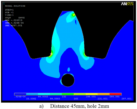
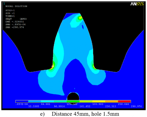
3.1 Holes at the center of the tooth
The first step toward reducing the stresses near the fillet is by stress relief holes, the hole is located at the center of the tooth. The analysis is performed by varying the location of the hole along the center of the tooth from the center of the gear, as shown in Figure 2.
Figure 2. Central hole at the center of the tooth
The diameter of the hole is chosen as 1.5 mm and 2 mm, and its distance are varying from 45 – 61 mm from the center of the gear. The optimization procedure used is to vary the distance of the holes at the specified range and finding the location of the minimum stress concentration value.
Figure 3. Holes at the mid-space width between two adjacent teeth
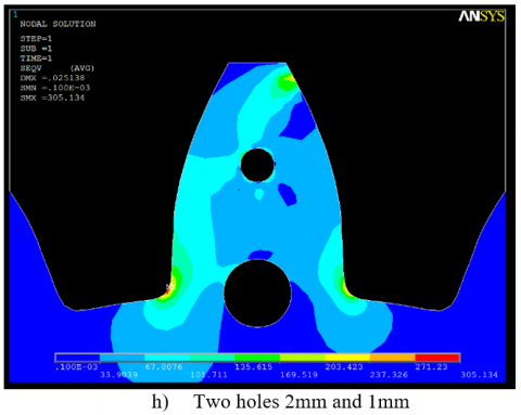
3.2 Holes at mid-space between teeth
The second step toward reducing the stresses near the fillet is by using stress relief holes located at the central distance of space width between the two adjacent teeth. The analysis is performed by varying the location of the holes from the center of the gear, as shown in Figure 3.
The diameter of the hole is chosen as 1.5 mm and 2 mm, and its distance are varying from 45 – 50 mm from the center of the gear. The optimization procedure used is to vary the distance of the holes at the specified range and finding the value of the minimum stress concentration.
3.3 Half circular cut at mid-space between teeth
The third step for reducing the maximum stresses is by using half circular cut located at the central distance between the two adjacent teeth at the dedendum circle. The analysis is performed by varying the diameter of the in their specified locations, as shown in Figure 4.
Figure 4. Half circular cut at the mid-space width between adjacent teeth at the dedendum circle
The diameters of the half circular cut are varied from 1 mm to 3 mm at a step of 0.25 mm. Accordingly, the optimization procedure used was to finding the value of the minimum stress concentration within these variations.
The number of the teeth used is 20 with a module of 6, the material used was steel with modulus of elasticity of 200 GPa and Poisson's ratio of 0.3, the other information is tabulated in Table 1.
Table 1. Data used for the spur gear used in the FEM analysis
|
Type of gear |
Involute, full depth teeth |
|
Gear’s Material |
Steel |
|
Modulus of elasticity |
200 GPa |
|
Module, m |
6 mm |
|
Pressure angle |
20 deg |
|
Addendum |
1×m |
|
Dedendum |
1.25×m |
|
Poisson’s ratio |
0.3 |
|
Number of teeth |
20 |
Figure 5. Effect central holes on the stress values and distributions
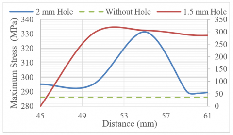
Figure 6 showed the results of this case, for the 2 mm hole the worst case at the distance 55 mm from the center of the gear under consideration, while the 1.5 mm showed almost plateau behavior after a distance of 50 mm with clear behavior of increasing the stress concentration.
The second case in the analysis of reducing the stresses near the fillet is by using stress relief holes located at the central distance of space width between the two adjacent teeth, the diameter of the holes is chosen as 1.5 mm and 2 mm, and its distance are varying from 45 – 50 mm from the center of the gear. The distance variations affect the stress distributions with generally accepted to beneficial results, as these holes lowered the maximum values of the stress concentration near the tooth fillet in Figure 7.
Figure 6. Stress variation vs. central holes distance
Figure 7. Holes located at mid-space width between two adjacent teeth on the stress concentration near the fillet
Figure 8 showed the results of the second case, for the 2 mm hole the stress values are lower below the value without modification at the distance of 49 mm and greater from the center of the gear under consideration, while the 1.5 mm lower stress of 268.452 MPa with clears improvement in the stress distribution.
The third case for reducing the maximum stresses is by using half circular cut located at the central distance between the two adjacent teeth at the dedendum circle, the diameters of these half circular cut are varied from 1 mm to 3 mm at a step of 0.25 mm. Accordingly, the effect of this changes on the stress concentrations are shown in Figure 9. Figure 10 showed the maximum stress variation, near the fillet of the spur gear, due to changing the diameter of the half circular cut located at the mid-space width between the two adjacent teeth, from these results the lowest value was 214.778 MPa for the 2.75 mm half circular cut.
Figure 8. Stress concentration variation effect due to changing distance of holes located at mid-space width between two adjacent teeth
Figure 9. Effect of changing the diameter of the half circular cut, located at the mid-space width between adjacent teeth, on the stress concentration near the fillet of the spur gear
Figure 10. Maximum stress variation, near the fillet of the spur gear, due to changing the diameter of the half circular cut located at the mid-space width between the two adjacent teeth
The current paper proposes a method for reducing the maximum bending stress concentration near the tooth fillet of a symmetric spur gear by focusing solely on geometrical feature aspects. Drilling relief holes, particularly near the fillet, and half circular cuts in the zone between adjacent teeth were used in the optimization procedure. The locations and sizes of these holes or cuts are optimized to change the stress distribution near the fillets, resulting in reduce bending stresses near the fillets. To evaluate the stress distribution and perform geometric optimization, finite element methods were used for formulation and modeling. These gear geometry changes and redistribute the bending stress near the high stress region, resulting in a 25% reduction in stress concentration. As a result, this paper demonstrates that significant reductions in maximum bending stress are possible. This implies relatively small gear dimensions and/or a compact gearing system with low weight and cost.
[1] Helldörfer, B., Haas, M., Kuhn, G. (2008). Automatic coupling of a boundary element code with a commercial finite element system. Advances in Engineering Software, 39(8): 699-709. https://doi.org/10.1016/j.advengsoft.2007.07.003
[2] Natali, C., Battarra, M., Dalpiaz, G., Mucchi, E. (2021). A critical review on FE-based methods for mesh stiffness estimation in spur gears. Mechanism and Machine Theory, 161: 104319. https://doi.org/10.1016/j.mechmachtheory.2021.104319
[3] Nouri, M., Husain, I.A. (2000). Boundary element method for axisymmetric solids under non-symmetrical surface loads. Communications in Numerical Methods in Engineering, 16(12): 867-875. https://doi.org/10.1002/1099-0887(200012)16:12%3C867::AID-CNM313%3E3.0.CO;2-A
[4] Sánchez, M.B., Pleguezuelos, M., Pedrero, J.I. (2019). Influence of profile modifications on meshing stiffness, load sharing, and transmission error of involute spur gears. Mechanism and Machine Theory, 139: 506-525. https://doi.org/10.1016/j.mechmachtheory.2019.05.014
[5] Pleguezuelos, M., Sánchez, M.B., Pedrero, J.I. (2021). Analytical model for meshing stiffness, load sharing, and transmission error for spur gears with profile modification under non-nominal load conditions. Applied Mathematical Modelling, 97: 344-365. https://doi.org/10.1016/j.apm.2021.03.051
[6] Fredette, L., Brown, M. (1997). Gear stress reduction using internal stress relief features. Journal of Mechanical Design, 119(4): 518-521. https://doi.org/10.1115/1.2826398
[7] Spitas, V., Costopoulos, T., Spitas, C. (2005). Increasing the strength of standard involute gear teeth with novel circular root fillet design. American Journal of Applied Sciences, 2(6): 1058-1064. https://doi.org/10.3844/ajassp.2005.1058.1064
[8] Di Francesco, G., Marini, S. (1997). Structural analysis of asymmetrical teeth: Reduction of size and weight. Gear Technology (USA), 47-48.
[9] Yang, S.C. (2005). Mathematical model of a helical gear with asymmetric involute teeth and its analysis. The International Journal of Advanced Manufacturing Technology, 26: 448-456. https://doi.org/10.1007/S00170-003-2033-Z
[10] Deng, G., Nakanishi, T., Inoue, K. (2003). Bending load capacity enhancement using an asymmetric tooth profile (1st report, influences of pressure angle on tooth root stress and bending stiffness). JSME International Journal Series C Mechanical Systems, Machine Elements and Manufacturing, 46(3): 1171-1177. https://doi.org/10.1299/jsmec.46.1171
[11] Litvin, F.L., Lian, Q., Kapelevich, A.L. (2000). Asymmetric modified spur gear drives: Reduction of noise, localization of contact, simulation of meshing and stress analysis. Computer Methods in Applied Mechanics and Engineering, 188(1-3): 363-390. https://doi.org/10.1016/S0045-7825(99)00161-9
[12] Chavadaki, S., Kumar, K.N., Rajesh, M.N. (2021). Finite element analysis of spur gear to find out the optimum root radius. Materials Today: Proceedings, 46: 10672-10675. https://doi.org/10.1016/j.matpr.2021.01.422
[13] Liu, P., Zhu, L., Gou, X., Shi, J., Jin, G. (2021). Modeling and analyzing of nonlinear dynamics for spur gear pair with pitch deviation under multi-state meshing. Mechanism and Machine Theory, 163: 104378. https://doi.org/10.1016/j.mechmachtheory.2021.104378
[14] Zhang, C., Dong, H., Wang, D., Dong, B. (2022). A new effective mesh stiffness calculation method with accurate contact deformation model for spur and helical gear pairs. Mechanism and Machine Theory, 171: 104762. https://doi.org/10.1016/j.mechmachtheory.2022.104762
[15] Kalay, O.C., Doğan, O., Yılmaz, T.G., Yüce, C., Karpat, F. (2021). A comparative experimental study on the impact strength of standard and asymmetric involute spur gears. Measurement, 172: 108950. https://doi.org/10.1016/j.measurement.2020.108950
[16] Dong, P., Zuo, S., Tenberge, P., Uelpenich, R., Xu, X., Liu, Y., Wang, S., Lai, J. (2022). Rapid hob tip corner optimization of spur gears for increasing bending strength. International Journal of Mechanical Sciences, 224: 107322. https://doi.org/10.1016/j.ijmecsci.2022.107322
[17] Kulangara, A.J., Rao, C.S.P., Bose, P.S.C. (2018). Generation and optimization of lattice structure on a spur gear. Materials Today: Proceedings, 5(2): 5068-5073. https://doi.org/10.1016/j.matpr.2017.12.085
[18] Zou, T., Shaker, M., Angeles, J., Morozov, A. (2014). Optimization of tooth root profile of spur gears for maximum load-carrying capacity. In International Design Engineering Technical Conferences and Computers and Information in Engineering Conference, 46322: V02BT03A017. https://doi.org/10.1115/DETC2014-34568
[19] Zou, T., Shaker, M., Angeles, J., Morozov, A. (2017). An innovative tooth root profile for spur gears and its effect on service life. Meccanica, 52(8): 1825-1841. https://doi.org/10.1007/s11012-016-0519-7
[20] Schneider, L., Roth, Z., Münzer, M., Lubos, F. (2017). Toothing of a gearwheel. United States Patent: US 20170284529A1.
[21] Math, V.B., Chand, S. (2004). An approach to the determination of spur gear tooth root fillet. Journal of Mechanical Design, 126(2): 336-340. https://doi.org/10.1115/1.1666891
[22] Pedersen, N.L. (2009). Reducing bending stress in external spur gears by redesign of the standard cutting tool. Structural and Multidisciplinary Optimization, 38(3): 215-227. https://doi.org/10.1007/s00158-008-0289-5
[23] Zhao, X. (2014). Increasing bending strength in spur gears using shape optimization of cutting tool profile. Australian Journal of Mechanical Engineering, 12(2): 208-216. https://doi.org/10.7158/M13-027.2014.12.2
[24] Uelpenich, R., Tenberge, P. (2019). Fast tooth root load capacity optimization based on improved design of hob geometry. In MATEC Web of Conferences, 287: 01011. https://doi.org/10.1051/matecconf/201928701011
[25] Dong, P., Zuo, S., Du, S., Tenberge, P., Wang, S., Xu, X., Wang, X. (2020). Optimum design of the tooth root profile for improving bending capacity. Mechanism and Machine Theory, 151: 103910. https://doi.org/10.1016/j.mechmachtheory.2020.103910
[26] Kapelevich, A., Shekhtman, Y. (2009). Tooth fillet profile optimization for gears with symmetric and asymmetric teeth. Gear Technology, 26(7): 73-79.
[27] Siva, R., Vimalson, K. A., Yogeshkumar, P., Joy, N., Sangeetha, M. (2021). Study on optimization of spur gear performance with titanium carbide incorporated aluminium matrix composite. Materials Today: Proceedings, 44: 3686-3691. https://doi.org/10.1016/j.matpr.2020.10.804
[28] He, R., Tenberge, P., Xu, X., Li, H., Uelpenich, R., Dong, P., Wang, S. (2021). Study on the optimum standard parameters of hob optimization for reducing gear tooth root stress. Mechanism and Machine Theory, 156: 104128. https://doi.org/10.1016/j.mechmachtheory.2020.104128
[29] Kishore, S.N., Reddy, A.V.V., Rao, L.B. (2022). Design and optimization of spur gears in a single stage reduction gear box. Materials Today: Proceedings, 60: 2010-2017. https://doi.org/10.1016/j.matpr.2022.01.258
[30] Magrini, A., Lazzari, S., Marenco, L., Guazzi, G. (2017). A procedure to evaluate the most suitable integrated solutions for increasing energy performance of the building’s envelope, avoiding moisture problems. International Journal of Heat and Technology, 35(4): 689-699. https://doi.org/10.18280/ijht.350401