Bambang Bagus Harianto* | Ghaidaa Raheem Lateef Al-Awsi | Ramaswamy Sivaraman![]() | Mukhiddin Anarboev | Vadim V. Ponkratov
| Mukhiddin Anarboev | Vadim V. Ponkratov![]() | Serge Lawrencenko | Surendar Aravindhan | Tatiana A. Bloshenko
| Serge Lawrencenko | Surendar Aravindhan | Tatiana A. Bloshenko![]() | Iskandar Muda
| Iskandar Muda![]()
(This article is part of the Special Issue Hybrid Renewable Energy Systems and Integration)
© 2023 IIETA. This article is published by IIETA and is licensed under the CC BY 4.0 license (http://creativecommons.org/licenses/by/4.0/).
OPEN ACCESS
Fuel cells serve as environmentally friendly alternatives to fossil fuels by providing clean energy. Integrating a fuel cell with an energy storage system, such as a battery, results in cost savings and performance improvements. The battery functions as an energy storage source, enabling the regulation and maintenance of fuel cell power at acceptable levels. Introducing an innovative and optimal power management method for hybrid electric energy supply systems can significantly contribute to the advancement of renewable resources by reducing costs, enhancing energy efficiency, increasing system reliability, and improving fuel cell lifespan. In this study, a membrane exchange fuel cell model, combined with a battery, is presented using MATLAB. The results demonstrate an increase in fuel cell life, energy efficiency, and output power quality. The state of charge (SOC) of the battery fluctuates between 52% and 34%, while the output power of the proton exchange membrane fuel cell (PEMFC) ranges between 30 and 20 watts. It is worth noting that, during the 1,200-second power supply process using the proposed strategy, only six PEMFC working points have changed.
renewable energies, hybrid systems, power management, fuel cell
Fuel cell technology, as a clean energy source, offers an environmentally friendly alternative for various industrial applications, replacing fossil fuels and reducing pollution. However, relying solely on a fuel cell system may not meet all load demands, particularly during peak load periods. Therefore, integrating a fuel cell system with an energy storage system (ESS) can lead to cost reductions and performance improvements. In many hybrid applications, batteries serve as the energy storage source, regulating and maintaining fuel cell power at acceptable levels. Given the distinct characteristics of fuel cell and battery systems, an appropriate power management strategy is required to enhance system performance and minimize fuel cell consumption.
Numerous studies have addressed the combination of fuel cell and battery systems in vehicle applications [1, 2]. In these systems, a controller and phased DC mode adjustment were employed for power distribution management. The primary objective of the controller was to stabilize the battery charging bus voltage within an acceptable range. Research on combined fuel cell and supercapacitor systems in vehicle applications has focused on fuzzy controller algorithms capable of determining the necessary power from the fuel cell and maintaining the bus voltage within a nominal range [3, 4].
Other investigations have explored the integration of fuel cell systems with batteries and supercapacitors in hybrid electric vehicles [5, 6]. By employing a smart strategy and a fuzzy controller, optimal energy management in hybrid fuel cell vehicles' power sources was assessed, with results indicating that maintaining the battery and supercapacitor's state of charge enhances dynamic performance and promotes fuel efficiency. In another study, a photovoltaic (PV) system was utilized to produce hydrogen, while a fuel cell system generated heat and electricity [7, 8]. This research examined the technical and economic feasibility of using a combined PV-fuel cell system in residential applications for simultaneous electricity and heat production. Technical and economic analyses revealed that while PV systems are currently the most economical combined system, fuel cells are not justifiable for residential use. However, it is anticipated that with rising energy carrier prices and decreasing installation costs, fuel cell systems will become more economically viable in the future.
In 2020, research on bidirectional converter control in a polymer fuel cell-based hybrid system was presented [9, 10]. The desired controller for bidirectional converter control was sliding mode control, a nonlinear and disturbance-resistant controller. However, the system employed in this study consisted only of a fuel cell system and did not incorporate a combined fuel cell and battery system. Another study examined the modeling of a polymer fuel cell with a proton exchange membrane in a hybrid power source system [11, 12]. In this system, a fuel cell was connected to a step-up DC converter, and power was controlled by an inverter. The fuel cell and its power management were analyzed from a mechanical-dynamic perspective, but factors such as fuel cell efficiency were not considered. Additionally, a simplified approximate circuit was used to assess the electrical behavior of the proton exchange membrane fuel cell (PEMFC).
Research has also investigated and controlled the inlet air of the compressor connected to the PEMFC in a hybrid energy source [13-16]. This hybrid power source utilized a combination of PEMFC and Li-ion batteries to supply electricity to a permanent magnet electric motor. However, this study focused solely on controlling the air pressure entering the fuel cell, without addressing critical issues such as energy control strategy, battery charge and discharge rates, fuel cell efficiency, and more.
In this paper, a power management strategy is implemented to optimally distribute power between the battery and the fuel cell. The current study assumes that the battery can receive and supply electrical power through a bidirectional converter, while a one-way step-up converter is used for the PEMFC.
2.1 PEM fuel modeling
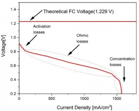
A fuel cell converts chemical energy directly into electrical energy. There are three types of losses in a fuel cell: activation losses, ohmic losses, and concentration losses. The polarization curve of the fuel cell showing its losses is shown in Figure 1.
An important electrochemical phenomenon that relates cell voltage to load current changes in a fuel cell system is the double layer capacitive charging effect. Capacitances in electric double layer capacitors range from several thousand to several hundred thousand farads, making them capacitance-rich devices. Examples of high power density devices are shown. Typical equivalent circuit model is made up of three distinct electrical components. The electrical equivalent circuit considering the effect of double layer capacitive charging is shown in Figure 2 [17, 18].
2.2 Fuel cell simulation at different temperatures and pressures
By using model simulation at different temperatures, which the suitable performance range for PEM fuel cell system is between 55 and 85 degrees Celsius, the performance of fuel cell has been drawn by applying step current (1A) polarization curve at different temperatures. Temperature, load, and fuel/oxidant flow rates affect single fuel cell voltage. The polarization curve illustrates cell voltage versus operational current density. When the current (load) of a fuel cell changes, its heat and water balances vary, and it may take time for a new equilibrium to be reached. Allow the fuel cell time to establish equilibrium while testing. The equilibrium time varies based on the load of the fuel cell. In the polarization curves, it can be seen that with the increase in temperature, the polarization curve is shifted upwards and it can be said that with the increase in temperature, the amount of current and voltage taken from the stack increases. Since it can be seen from Eqns. (1)-(2) that the voltage is not constant and finally the fuel cell stack voltage has a direct relationship with the stack temperature and with the increase in temperature, the fuel cell voltage increases and in this simulation It can be seen that the graph of the fuel cell polarization curve at temperatures of 7,327 degrees Kelvin (554 degrees Celsius) to 7,357 degrees Kelvin (584 degrees Celsius) with the increase in temperature, the voltage curve tends to increase the voltage. The simulations and tests performed in the curve of Figure 3 at constant pressure and at variable temperature for a stack of 500 watts up to a current of 25 amps and anode pressure of 1 bar and cathode pressure of 1 bar have been performed below.
$V_{F C}=E_{\text {Nernst }}-V_{\text {act }}-V_{\text {canc }}-V_{\text {ohmic }}$ (1)
$\begin{aligned} E_{\text {mene }}=1.229 & -\left(8.5 \times 10^{-4}\right)(T-298.15) \\ & +4.308 \times 10^{-5} \times T \\ & \times \ln \left(P_{H_2}+\frac{1}{2} P_{\mathrm{O}_2}\right)\end{aligned}$ (2)
where, VFC is fuel cell voltage, Vact, Vcanc and Vohmic are Activation, concentration, and ohmic voltage drop respectively. T is Fuel cell temperature.
Figure 1. Fuel cell polarization curve (voltage-current curve)
Figure 2. Electric equivalent circuit of a fuel cell with a double charging capacitor
Figure 3. Polarization curve obtained from simulation at different temperatures
3.1 Effect of cathode pressure on polymer fuel cell performance
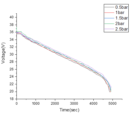
In the polarization curves (Figure 4), with increasing cathode pressure, the polarization curve is shifted upwards and it can be said that with increasing cathode pressure, the amount of current and voltage taken from the stack increases [19, 20]. The model related to the fuel cell system, which shows the performance and model of the polymer fuel cell, has been simulated in MATLAB software and Simulink environment.
Figure 4. Polarization curve obtained from simulation at different cathode pressure
3.2 Power condition unit (PCU)
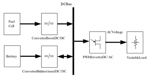
The output voltage of the fuel cell in series stacks is an uncontrolled DC voltage that fluctuates with load changes. This voltage must be converted to controlled DC voltage. By raising the load current, the output voltage of the fuel cell will noticeably fall. The PCU unit controls the electrical frequency and keeps the harmonics at an acceptable level. The overall configuration of the system includes a fuel cell, after which a boost converter is placed, and also includes a battery bank, which is placed after the bidirectional converter battery and then an inverter. The controlled voltage obtained after being filtered is sent to the AC/DC inverter. The boost converter is placed as an intermediary between the fuel cell system and the inverter system. Fuel cell systems connected to the grid include a storage battery. Fuel cell systems connected to the network include a storage battery. The topology of this system is shown in the Figure 5.
Figure 5. The topology of system
3.3 DC/DC boost converter
The power converter must protect the converter system against output fluctuations, reverse currents and sudden load changes and guarantee its full life. The output voltage is always greater than the input voltage. The equipment that is powered by a battery uses a DC/DC step-up converter to produce a voltage higher than the battery voltage [21, 22]. The main advantage of the boost converter is high efficiency and a small number of components, and it can convert the unregulated voltage into the desired regulated voltage by changing the duty cycle at a high switching frequency and reduce the size and cost of energy storage components.
3.4 Fuel cell with proton exchange membrane
Figure 6 shows the voltage and current polarization curves in a fuel cell stack. As the fuel cell current increases, the voltage at both ends decreases. According to the characteristic curve of the fuel cell, three performance areas can be defined for the fuel cell. In the ohmic performance region, the cell voltage decreases linearly with increasing current. Fuel cell is usually used in this work area. In the gas volume transfer area where the current exceeds the upper limit of safe operation, the battery voltage decreases rapidly and the use of fuel cells in this area should be avoided, because the fuel cells may be damaged due to the lack of hydrogen.
Figure 6. Fuel cell voltage-current curve
3.5 Suggested strategy
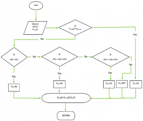
The characteristics of the hybrid power system, which consists of PEMFC and Li-ion batteries, are shown in Table 1. The proposed strategy is presented in the same manner as the algorithm in Figure 6, with the intention of enhancing energy efficiency, fuel cell lifespan, and reliability. The suggested method is evaluated based on the percentage of charge remaining in the battery, and the calculation of the output power of the PEMFC is planned to be performed based on the percentage of charge remaining in the battery. After determining the required power and state of charge of the battery using the flowchart in Figure 7, the suggested method then compares the required power to the maximum power that the battery is capable of producing in order to determine the sequence in which the fuel cell should be activated.
Table 1. Specifications of battery and fuel cell in hybrid power system
|
PFMC H-30 |
Li-ion Battery |
||
|
Voltage |
8.5 V |
Voltage |
18 V |
|
Current |
3.8 A |
Capacity |
2.6 Ah |
|
Power |
30 W |
Energy |
39.4 W |
Figure 7. Flowchart of the proposed power management strategy
Optimum power management in the hybrid energy supply system is one of the most important design parameters of electric energy supply sources. Therefore, getting familiar with the more specialized features of fuel cells and batteries, along with examining the results of their simulation, will play a significant role in improving the output power of the system. In this section, simulation and programming Li-ion battery equations have been done to know the power level, state of charge of the battery (SOC) and its internal resistance value. Simulating the effective capacity (discharge) of the battery, simulating the way the battery works and simulating the internal resistance of the battery provides the possibility of proper knowledge of the battery's condition in line with power management.
The battery used in this section is Cell Li-ion 18650 Sony. In this paper, an Li-ion battery with an output voltage of 16 volts and a capacity of 2.2 ampere-hours is used, so that the conditions for comparing the results are the same as the study [23, 24]. Li-ion battery equivalent circuit are shown in Figure 8.
Figure 8. Li-ion battery equivalent circuit
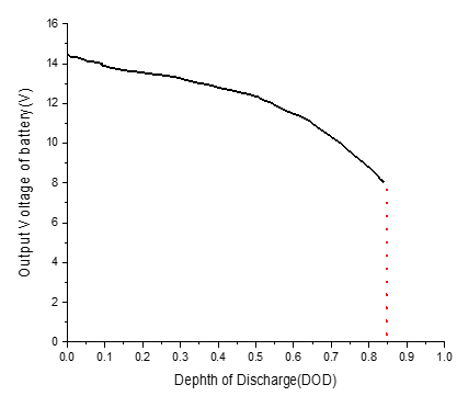
Figure 9 shows the output voltage curve of the simulated battery, which indicates that the simulated model matches the curve provided by its manufacturer [25, 26].
Figure 9. Modeled battery voltage according to DOD
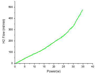
In this section, Stack Cell Fuel 30-H is simulated based on Horizon cell. According to the manufacturer's catalog, this fuel cell consists of 13 Horizon stack cells. The output results related to Horizon 30 are shown in the figures below, which shows that it matches the results of the manufacturer. The current-voltage curve of the aforementioned fuel cell is shown in Figure 10. It should be mentioned that the rated voltage and current of the H-30 fuel cell are 8.6 volts and 3.4 amps, respectively. Also, the curve of hydrogen fuel consumption in the 30-H fuel cell has been obtained according to Figure 11.
Figure 10. The simulated power-current curve of H-30 PEMFC
Figure 11. Hydrogen consumption rate according to power in H-30 fuel cell
In the proposed strategy, in order to prevent rapid changes in the power of the fuel cell, only its four working points have been used as the optimal performance conditions of the PEMFC. The selected points are determined based on the criteria of fuel consumption and suitable range.
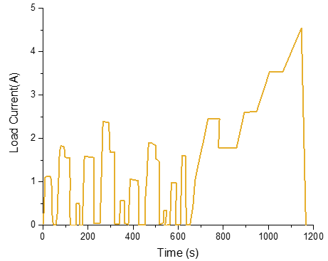
The load and power curve of NEDC pseudo-Like has been simulated and investigated through MATLAB programming simulation. The hybrid power system should be able to supply the required power of the load like NEDC. In this research, the output voltage of the energy production system equipped with a DC converter is considered to be around 24 volts. The simulated load curve is shown in Figure 12 the average value of the load current is 1.4 amps and the maximum current value is around 4.5 amps.
Figure 12. NEDC load curve according to time
In the proposed strategy, the battery power, battery SOC and PEMFC output power are examined and observed at every moment. In addition, in the proposed strategy, the instantaneous values of battery voltage, hydrogen consumption rate and PEMFC voltage are also observed and reviewed. Finally, in order to facilitate the comparison of the answer obtained with other references, the power of each of the power sources in the proposed strategy has been collected in Like NEDC load curve, battery power, battery SOC and PEMFC power are respectively shown in the figure below. According to the shape, the average power of the battery is around 9 watts, the maximum power is 90 watts and the maximum received power is around 30 watts. SOC battery in the range of 52% to 34% has changed and the output power of PEMFC is 30 and 20 watts. It should be mentioned, in the process of power supply by the proposed strategy, only 6 PEMFC working points have changed during the period of 1,200 seconds (Figure 13).
Figure 13. Summary of the output response in terms of time in the proposed strategy
In recent years, fuel cell systems are very important as one of the sources of electric power generation. But these resources alone will not be able to provide the power of dynamic loads, especially in fast dynamic applications. The hybrid system consisting of fuel cell and battery combines the high power density of the fuel cell with the high energy density of the battery and is well responsive to the power demand of the relevant systems. Fuel cells in the proposed strategy can provide the required energy while not having to feed the required peak power in most of the rapid power changes. Due to their special structural features, fuel cells show a slow response to the required powers of the system. Also, due to the slow reaction time of fuel cells, the output power cannot adapt to transient conditions. Therefore, load changes must be managed by an external power management system.
In the method that was suggested, decreasing the frequency of working point adjustments helps to lengthen the life of the fuel cell while simultaneously improving its optimal performance. In contrast to the other technique, the number of times the operating points of the fuel cell varied just six times in the power management strategy that was provided; nevertheless, this number changed twenty-five times in the other method [27]. In addition, the reduction in the selective PEMFC capacity and the selection of working points of the suggested approach have resulted in a lower amount of hydrogen fuel being consumed in comparison to the other methods. This can be attributed to the fact that the suggested approach utilizes different working points.
[1] Dursun, B., Aykut, E. (2019). An investigation on wind/PV/fuel cell/battery hybrid renewable energy system for nursing home in Istanbul. Proceedings of the Institution of Mechanical Engineers, Part A: Journal of Power and Energy, 233(5): 616-25. https://doi.org/10.1177/0957650919840519
[2] Tazay, A.F., Samy, M.M., Barakat, S. (2020). A techno-economic feasibility analysis of an autonomous hybrid renewable energy sources for university building at Saudi Arabia. Journal of Electrical Engineering and Technology, 15(6): 2519-2527. https://doi.org/10.1007/s42835-020-00539-x
[3] Suresh, V., Muralidhar, M., Kiranmayi, R. (2020). Modelling and optimization of an off-grid hybrid renewable energy system for electrification in a rural areas. Energy Reports, 6: 594-604. https://doi.org/10.1016/j.egyr.2020.01.013
[4] Eroglu, M., Dursun, E., Sevencan, S., Song, J., Yazici, S., Kilic, O. (2011). A mobile renewable house using PV/wind/fuel cell hybrid power system. International Journal of Hydrogen Energy, 36(13): 7985-7992. https://doi.org/10.1016/j.ijhydene.2011.01.046
[5] Ahmadi, M.H., Ahmadi, M.A., Feidt, M. (2016). Optimisation des performances d’un cycle de brayton irréversible solarisé à compressions et détentes multiples sur la base d’un algorithme génétique multi-objectif. Oil and Gas Science and Technology, 71(1). https://doi.org/10.2516/ogst/2014028
[6] Alavi, F., Park Lee, E., van de Wouw, N., De Schutter, B., Lukszo, Z. (2017). Fuel cell cars in a microgrid for synergies between hydrogen and electricity networks. Applied Energy, 192: 296-304. https://doi.org/10.1016/j.apenergy.2016.10.084
[7] Ghenai, C., Albawab, M., Bettayeb, M. (2020). Sustainability indicators for renewable energy systems using multi-criteria decision-making model and extended SWARA/ARAS hybrid method. Renewable Energy, 146: 580-597. https://doi.org/10.1016/j.renene.2019.06.157
[8] Elkadeem, M.R., Wang, S., Azmy, A.M., Atiya, E.G., Ullah, Z., Sharshir, S.W. (2020). A systematic decision-making approach for planning and assessment of hybrid renewable energy-based microgrid with techno-economic optimization: A case study on an urban community in Egypt. Sustainable Cities and Society, 54: 102013. https://doi.org/10.1016/j.scs.2019.102013
[9] Al-Bonsrulah, H.A.Z., Alshukri, M.J., Mikhaeel, L.M., Al-Sawaf, N.N., Nesrine, K., Reddy, M.V., Zaghib, K. (2021). Design and simulation studies of hybrid power systems based on photovoltaic, wind, electrolyzer, and pem fuel cells. Energies, 14(9): 2643. https://doi.org/10.3390/en14092643
[10] Zahedi, R., Ahmadi, A., Sadeh, M. (2021). Investigation of the load management and environmental impact of the hybrid cogeneration of the wind power plant and fuel cell. Energy Reports, 7: 2930-2939. https://doi.org/10.1016/j.egyr.2021.05.008
[11] Awan, A.B., Zubair, M., Sidhu, G.A.S., Bhatti, A.R., Abo-Khalil, A.G. (2019). Performance analysis of various hybrid renewable energy systems using battery, hydrogen, and pumped hydro-based storage units. International Journal of Energy Research, 43(12): 6296-6321. https://doi.org/10.1002/er.4343
[12] Lei, G., Song, H., Rodriguez, D. (2020). Power generation cost minimization of the grid-connected hybrid renewable energy system through optimal sizing using the modified seagull optimization technique. Energy Reports, 6: 3365-3376. https://doi.org/10.1016/j.egyr.2020.11.249
[13] Molajou, A., Nourani, V., Afshar, A., Khosravi, M., Brysiewicz, A. (2021). Optimal design and feature selection by genetic algorithm for emotional artificial neural network (EANN) in rainfall-runoff modeling. Water Resources Management, 35(8): 2369-2384. https://doi.org/10.1007/s11269-021-02818-2
[14] Razmjoo, A., Gakenia Kaigutha, L., Vaziri Rad, M.A., Marzband, M., Davarpanah, A., Denai, M. (2021). A technical analysis investigating energy sustainability utilizing reliable renewable energy sources to reduce CO2 emissions in a high potential area. Renewable Energy, 164: 46-57. https://doi.org/10.1016/j.renene.2020.09.042
[15] Hailu Kebede, M., Bekele Beyene, G. (2018). Feasibility study of PV-wind-fuel cell hybrid power system for electrification of a rural village in Ethiopia. Journal of Electrical and Computer Engineering, 2018. https://doi.org/10.1155/2018/4015354
[16] Medina, Y., Fonticiella, O., Morales, O. (2017). Design and modelation of piping systems by means of use friction factor in the transition turbulent zone. Mathematical Modelling of Engineering Problems, 4(4): 162-167. https://doi.org/10.18280/mmep.040404
[17] Huang, M., He, W., Incecik, A., Cichon, A., Królczyk, G., Li, Z.X. (2021). Renewable energy storage and sustainable design of hybrid energy powered ships: A case study. Journal of Energy Storage, 43: 103266.
[18] Fathabadi, H. (2017). Novel standalone hybrid solar/wind/fuel cell power generation system for remote areas. Solar Energy, 146: 30-43. https://doi.org/10.1016/j.solener.2017.01.071
[19] Pirkandi, J., Mahmoodi, M., Ommian, M. (2017). An optimal configuration for a solid oxide fuel cell-gas turbine (SOFC-GT) hybrid system based on thermo-economic modelling. Journal of Cleaner Production, 144: 375-386. https://doi.org/10.1016/j.jclepro.2017.01.019
[20] Damo, U.M., Ferrari, M.L., Turan, A., Massardo, A.F. (2019). Solid oxide fuel cell hybrid system: A detailed review of an environmentally clean and efficient source of energy. Energy, 168: 235-246. https://doi.org/10.1016/j.energy.2018.11.091
[21] Khan, M.J. (2021). Review of recent trends in optimization techniques for hybrid renewable energy system. Archives of Computational Methods in Engineering, 28(3): 1459-1469. https://doi.org/10.1007/s11831-020-09424-2
[22] Oueslati, F. (2021). Hybrid renewable system based on solar wind and fuel cell energies coupled with diesel engines for Tunisian climate: Trnsys simulation and economic assessment. International Journal of Green Energy, 18(4): 402-423. https://doi.org/10.1080/15435075.2020.1865366
[23] Devrim, Y., Bilir, L. (2016). Performance investigation of a wind turbine–solar photovoltaic panels–fuel cell hybrid system installed at incek region-ankara, Turkey. Energy Conversion and Management, 126: 759-766. https://doi.org/10.1016/j.enconman.2016.08.062
[24] Samy, M.M., Barakat, S., Ramadan, H.S. (2020). Techno-economic analysis for rustic electrification in egypt using multi-source renewable energy based on PV/ wind/ FC. International Journal of Hydrogen Energy, 45(20): 11471-11483. https://doi.org/10.1016/j.ijhydene.2019.04.038
[25] Kwon, L., Cho, D.S., Ahn, C. (2021). Degradation‐conscious equivalent consumption minimization strategy for a fuel cell hybrid system. Energies, 14(13): 3810. https://doi.org/10.3390/en14133810
[26] Fu, Z.C., Chen, Q.H., Zhang, L.Y., Zhang, H.R., Deng, Z.H. (2021). Research on ADHDP energy management strategy for fuel cell hybrid power system. International Journal of Hydrogen Energy, 46(57): 29432-29442. https://doi.org/10.1016/j.ijhydene.2021.02.055
[27] Wang, Y.X., Ou, K., Kim, Y.B. (2015). Modeling and experimental validation of hybrid proton exchange membrane fuel cell/battery system for power management control. International Journal of Hydrogen Energy, 40(35): 11713-11721. https://doi.org/10.1016/j.ijhydene.2015.03.073