Kennedy Okokpujie*![]() | Imhade P. Okokpujie
| Imhade P. Okokpujie![]() | Adebayo Tunbosun Ogundipe
| Adebayo Tunbosun Ogundipe![]() | Chukwuka Daniel Anike | Obedafe Blessed Asaboro | Akingunsoye Adenugba Vincent
| Chukwuka Daniel Anike | Obedafe Blessed Asaboro | Akingunsoye Adenugba Vincent![]()
© 2023 IIETA. This article is published by IIETA and is licensed under the CC BY 4.0 license (http://creativecommons.org/licenses/by/4.0/).
OPEN ACCESS
Cattle farming is undoubtedly one of the most lucrative subsectors of agriculture globally, but faces significant challenges such as the inability to monitor cattle health and location, and cattle rustling. This research aimed to develop a system to resolve these issues using sensors to monitor ambient/body temperature, magnetometer, and GPS. The proposed system comprises these components in a head strap. Data were transmitted via a long-range (LoRa) module to a base station, then to a website and mobile app using General Packet Radio Service (GPRS)/satellite. Information was received and monitored in real-time. Testing showed the system could be deployed in vast farmland to monitor cattle health and location satisfactorily in real-time. Unlike other systems, this system monitors cattle health and location with/without mobile network coverage due to satellite communication. In conclusion, the proposed system monitors cattle health and location status with or without mobile network coverage due to an alternative communication channel (satellite) compared to other related systems.
cattle, health status, location tracking system, web application, mobile application
Agriculture plays a pivotal role in generating revenue in Nigeria, across Africa, and globally. The cattle industry, in particular, is vital to the Nigerian economy. Cattle farming has proven to be a highly profitable subsector within the agricultural sphere, transforming many investors into multimillionaires and providing employment for numerous individuals [1]. Despite its economic benefits, cattle farming can be a stressful and demanding endeavor. Cattle herders often face significant challenges in maintaining control over their herds.
In sub-Saharan Africa and Nigeria, cattle farming encounters various obstacles, including the farmers' limited education, which hinders their ability to apply modern animal production techniques when traditional methods prove inefficient and unprofitable. The infrequent use of ranching techniques in Nigeria contributes to the occurrence of accidents as animal farmers guide their cattle along roads for grazing. Consequently, some cattle may be struck by vehicles, while others may fall victim to theft (cattle rustling). Furthermore, cattle herders often struggle to determine whether their animals receive adequate nourishment and may contend with their cattle's poor health without access to veterinary care or medication.
To address these challenges, this study proposes a system capable of monitoring cattle health, feeding habits, and location. The system comprises a wireless device, or head strap, affixed to the cattle's head, equipped with an infrared temperature sensor for continuous temperature monitoring and a multi-axis motion detector to track various cattle activities, such as eating, standing, lying down, and sleeping. Additionally, the device can locate and monitor individual cattle. The system includes a backup battery with a six-month lifespan and a satellite/internet modem installed at the dairy farm to collect data from the head strap (within a 2-mile radius). The modem transmits the collected data to a cloud system through the internet. The system also features a web dashboard and mobile app for analyzing the data obtained from the head strap.
Major issues in cattle farming include cattle rustling and the inability to detect illness or disease onset in cattle. Cattle theft significantly impacts the income and resources of herding communities, leading to long-term productivity decline and a potential reduction in Nigeria's organic protein and dairy supply [2]. Early disease detection in cattle is crucial; otherwise, the disease may spread to healthy cattle, resulting in death and substantial capital loss. Thus, implementing the proposed technology is essential, as it features a GPS tracking system to mitigate cattle rustling and a temperature-monitoring sensor for timely disease prediction, reducing capital loss and production costs.
The primary contribution of this research lies in the development of a system capable of not only monitoring cattle health status and location but also transmitting data through two alternating communication channels. Additionally, the system presents the information via mobile and web application interfaces.
The implementation of IoT-based cow health monitoring systems was suggested in studies [3-5] to monitor cattle health. The provision of information to users about individual animals was enabled through Internet of Things connectivity and android applications. The main advantage of these systems is that the day-to-day monitoring of animal conditions and the early detection of diseases by farmers were easily enabled. However, the implementation of these systems was found to be very expensive. The detection of all kinds of diseases and the tracking of animal locations were not possible due to the lack of a GPS system.
For the tracking of cattle grazing and the prevention of rustling, the use of GPS and GSM systems was proposed in studies [6-8]. Through the attachment of collars to cattle, the sending of SMS with the exact collar location to farmers was enabled, allowing the tracking of cattle location. The generation of location coordinates by the GPS module and their delivery to farmers as SMS along with warning messages through the GSM module were enabled by the collar. The main advantage of this system is that it can be used in large areas due to the use of GPS and GSM modules. The implementation of this system was found to be very affordable. However, the obtaining of livestock coordinates and the transmission of SMS messages were found to face delays due to the low quality of service supplied by local networks in some areas.
According to the authors of the study [9], the real-time monitoring of livestock whereabouts was enabled through an IoT-based system integrating limited-power wide-area technologies, the cloud, and virtualization services. The capture of location and activity data on a periodic basis and its transmission to the cloud system through LoRaWAN gateways for storage, processing and management were enabled, allowing easy access by users. The major advantage of this system is that little power is consumed and LoRa and LoRaWAN were used for long-range communication links.
In studies [10, 11], the use of sensors and GPS modules for the collection of cattle information and the tracking of their whereabouts was proposed. In the first study, the monitoring of pulse rate, body temperature, heart rate and respiratory rate was enabled through sensors. The transmission of signals from sensors to a server application for processing was allowed. Additionally, the tracking of a cow's whereabouts at any time was enabled through the use of a chip inserted into the cow connecting with GPS. The transmission of signals from sensors on cattle to the cloud through routers and then to farmers/veterinarians as SMS was enabled. The main advantage of this device is that information about cattle can be obtained from anywhere as all data is stored in the cloud, and it has a 3-layer ANN enabling accurate decision making. It was highly effective as a sophisticated cloud-based system detecting cattle health abnormalities and location to avoid rustling.
In study [12], a LoRa sensor network for monitoring pastured livestock location and activity was described. The sensor in this system comprises a low-cost CPU compatible with Arduino, a generic MPU-9250 motion sensor with 3-axis accelerometer, 3-axis magnetometer and 3-axis gyroscope, a generic GPS receiver and an RFM95W generic LoRa radio. The open-source Arduino IDE software was used to modify the central processing unit sampling frequency. The open-source Arduino IDE software was utilized in the programming of the sensors utilized in wearable sensors. The provision of specific information about each animal's behaviour throughout the day and the places where most time was spent on the farm by sensors was enabled. The advantages of using this system are that animal location can determine in real-time based on GPS data; it provides an inexpensive method to deploy flexible and efficient precision technologies for pastured livestock; it has obvious appeal as a low-risk solution and real-time data transmission about animals is provided. A disadvantage is that the system shape requires consideration due to the potential for animal hair to be caught in sensors, and size requires consideration due to the potential for damage from animals rubbing their heads against fences.
In the study [13], the use of a GPS system to monitor animal whereabouts was proposed. The study also included the use of temperature sensors and accelerometers to track animal temperature and movements, as well as the use of IoT to monitor general animal health. The transfer of data from the microcontroller to a PC through ZigBee transceivers to assess the severity of detected animal health issues was enabled. The accessing of information from any device on which the software was installed by farmers has been allowed. The advantages of this system are the use of IoT technology and GPS to track animal location and prevent theft. The disadvantages are that there are not enough sensors to provide accurate information about animal health, and the proposed system lacks water resistance, risking damage upon contact with water.
In the study [14], the aim was to monitor the heart rates and temperatures of unwell and distressed animals, as well as animal patients recovering from surgery or early therapy. The communication with the system using a web server and clients was enabled. The saving of data from heart rate and body temperature sensors on MySQL servers and display on a web browser upon receipt was enabled by the system. The warning or notification of veterinarians via messaging including a line messaging application when an animal's heart rate or temperature exceeds or falls below the normal range was enabled. The system design, extensive content and user-friendliness of the application provide acquired information from all users with a mean value. The total user satisfaction rating for the sick animal monitoring system was found to be 4.38, which is a respectable score. Performance of the device was found to be satisfactory and consistent with veterinarian best practices.
In the study [15], an electronic system for the wireless recording and transmission of micro-ruminant heart rates and skin temperatures was proposed. The monitoring system comprises a mobile base unit handled remotely and a stationary base unit placed on the animal under investigation. Communication between the mobile and stationary base units through an Xbee Series 2 radio frequency transmitter was enabled. The easy recording and transmission of physiological data by the electronic monitoring system were enabled. The proposed device tracked physiological reactions, especially heart rate monitoring. However, limited energy autonomy and inability to be used where mobile communication was not possible e.g., enclosed cages due to technical limitations were disadvantages. The system's distinguishing feature was the combination of data capture in memory and mobile connectivity. The use of a cellular connection to obtain physiological parameters decreased stress from the measurement method, improving data quality and enabling real-time data collection as animals were not tethered.
A method for farmers to detect and contrast their cattle's current health metrics to regular healthy reference parameters through real-time input value detection using data from pulse, humidity and temperature sensors sending them to an MSP430 microprocessor for control was proposed in study [16]. The transmission of an alarm message by the GSM module in the event of an emergency and the display of information on an LCD were enabled. The initial heart rate, temperature and humidity of the animals in this study were 77, 32.42 and 69, respectively. If these values change, an alarm was transmitted to the farmer's cell phone through GSM for further action. The theft of the wearable device could pose a severe security risk. A digital theft detecting system could be installed on the device or hardware to inform the user if a damaged belt was detached from cattle.
The investigation of cattle grazing patterns and behaviors in the grazing field studied the use of a water-resistant GPS monitoring collar device (TR20) for cows which tracks the activity of each cow during grazing through a networked system [17]. Following resolution of ambiguity, location fixes were accurate for almost one day with 95% accuracy for 8 minutes. The precise prediction of animal behavior was achieved, with active categorization of grazing location fixes evenly dispersed, while inactive fixes near water or in popular resting areas were clustered. The study focused on the deployment of a GPS tracking collar capturing data more efficiently through a cloud-based network. The movement of cattle in the feeding area creates a binary linear graph which can be used to determine components reacting to cattle. Animals exhibit a wide range of behaviors depending on species, so animal classification does not guarantee similar behavior. Thus, tracking changes in these animals' behavior is difficult.
In the study [18], the development of an automated monitoring system automatically tracking pig movement and assessing activities like locomotion, feeding, standing and drinking from 3D trajectory data was proposed. While predictions of drinking, feeding and standing were shown to be accurate, predictions of locomotion activities were not. An automated system using only one type of sensor, a video camera, tracked 3D pig locations and quantified several diagnostically valid behaviors non-invasively. The monitoring of behaviors like standing, feeding, drinking and not-feeding not-drinking (NNV) were enabled. The advantages of this system include the real-time monitoring of animal behavior providing insight into changes in welfare and allowing routine daily check-ups and observation of animals and livestock using a color video camera revealing changes in specific behaviors. However, the system requires many cameras to capture all animal movements and behaviors, making it very expensive to install and maintain.
The purpose of the research in the study [19] was to develop the first reliable telemetry system for the remote and continuous single-metabolite monitoring of glucose, lactate, glutamate, and ATP in mouse models using BioNano-Sensors. The project's control unit comprises a microcontroller in the center of the device. Software incorporated into the microcontroller enables responses to sensor inputs. Wi-Fi was used to send data collected by sensors. The procedure has been applied to domestic animals, cattle and other poultry species. It was easy to use, required less upkeep, and cost less. Furthermore, with advancements in technology, the majority of the modules.
The proposed embedded system is developed in the form of a head strap which is attached to the cattle head and would be able to monitor the health of cattle with the use of temperature sensors as shown in Figure 1, the pictorial representation of the System. The A9G microcontroller is responsible for collecting data from the sensors. When cattle are infected with a disease, their body temperatures vary from normal. When the temperature varies, the farmer will be notified by the mobile application or from the web. The system also has an agility detector that monitors various activities of cattle, such as eating, standing, lying down, sleeping, and so on. The way it does that is such that the agility has a range from 0-5. For example, if the agility reads 0, it means that the cattle have been in a stationary position for a while, which means it is either sleeping, sick, or maybe dead, while 1-2 means limited movement (e.g., regurgitating, standing etc.) but if it reads 3-5, it means they are involved in high activities such as moving, eating etc.
The environmental condition of the farm also plays a major role in maintaining the cattle’s health. Thus, an environmental sensor is included in the circuitry, so, when there is an increase in the environmental temperature or humidity, the farmer will be notified through the mobile application. In large areas or farms, farmers will be unable to keep track of the cattle's location and some of the cattle might be affected by diseases. The Global Positioning System (GPS) is used to track the location of the cattle on the farm. The SX1278 LoRa RF Module transmits data from the temperature sensor and multiple axis motion detector to a satellite/internet router installed in the dairy farms, where it is then relayed over the internet to a cloud system. The device comes with a backup battery that could work continuously for at least six months.
3.1 Hardware components
The hardware components consist of the following:
a) Temperature Sensor: The MLX90614 is a non-contact infrared thermometer. The TO-39 package contains both the IR-sensitive thermopile detector chip and the signal conditioning ASIC [20].
b) SX1278 LORA RF Module: In long-range communications, the SX1278 LoRa modules are employed. It has the potential to reduce current usage. The SX1278 features a sensitivity of -148 dBm and an average power of +20 dBm, as well as a long transmission distance and great durability [21].
c) SIM808 Module: The SIM808 module is a comprehensive Quad-Band GSM/GPRS module that incorporates GPS technology for satellite navigation. The compact architecture that integrates GPRS and GPS in an LCC package will save clients substantial time and money when developing GPS-enabled apps. It features an industry-standard interface and GPS capability, enabling the smooth tracking of variable assets in any location and at any time with signal coverage [22].
Figure 1. Picture representation of the system
d) UBLOX NEO GPS Satellite Module: The NEO-6M GPS module is a high-performance full GPS receiver with a built-in 25×25×4mm ceramic antenna for reliable satellite search. The power and signal indicators allow you to keep track of the module's status. They're low-power (ideal for battery-powered devices), cheap, and simple to use, and they're extremely popular among enthusiasts [23].
e) Micro-Controller A9G (GSM/GPRS+GPS Development Board): The A9G GSM/GPRS/GPS module is an Internet of Things (IoT) solution with a built-in GPS module that works with a dual-band GSM/GPRS network. It is commonly utilized in applications that include both GSM and GPS devices. The board has a small footprint and uses very little power [24].
f) Rockblock Satellite Module: The Rockblock satellite module is one of the device's most vital components. It enables the sending and receiving of short messages from anywhere on the planet with a clear view of the sky, far beyond the range of Wi-Fi and GSM networks. RockBLO is always available when other networks are offline, and an emergency communication is required. RockBLOCK is powered by an Iridium 9602 satellite modem. The 9602 modules are connected to the RockBLOCK through an antenna and a 0.1" header with power and data connections [25].
g) Charger Controller: The charger controller's main purpose is to keep the battery bank from overcharging. The controller monitors the battery bank and transfers energy from the battery bank to a dump load when the bank is fully charged [26].
h) Jumper Cables: Male-to-male jumpers are particularly useful for connecting standard 0.1" male header pins often found on breakout boards to male header contacts, such as those on a solderless breadboard. Additionally, extension cords can be created by connecting the female end to the male end of another cable [27].
i) Triple-axis Compass Magnetometer: The triple-axis compass magnetometers measure the magnetic field along one or more axes. Using a magnetometer, it is possible to transform an Arduino into a digital compass. They are ideal for remote-controlled vehicle guidance and navigation systems. Even electric currents in cables can be detected with their help [28].
3.2 Software elements
a) C# (C SHARP): this programming language was developed by Microsoft and runs on the .NET framework. It is based on other languages like C, C++ and is used for the development of database, webservice and various other applications.
b) CSS: The language is mainly used for designing or styling a web page. It describes how the different elements of the page will be laid out and displayed on screen or any other way. It is used here for the UI styling.
c) JavaScript: This is a dynamic and the most popular programming language for the web. Very detailed codes/instruction can be written through this, and it is used to design how the user/admin will interact with the webpage for in browser code. It is employed here for those purposes.
d) Blazor: This is a free and open-source framework created by Microsoft. It is a UI framework with the ability to create great web user interfaces (UI) using just HTML, CSS and C#. It is used here for developing the administrator or user interface.
e) HTML: The Hypertext Markup Language is used to organize a web page and the material that is displayed on it.
f) MAUI FRAEMEWORK: It’s an open-source framework that evolved from Xamarin. Forms extended from mobile to desktop environments, with UI controls redesigned for performance and extensibility. Using.NET MAUI, you can build cross-platform applications using a single project, but, if necessary, you could include platform-specific source code and resources.
3.3 Working principle of the system
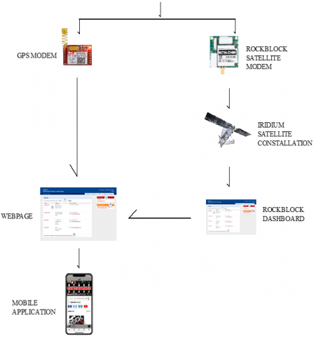
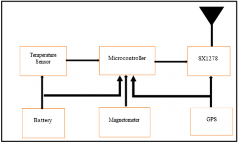
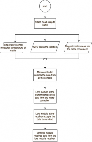
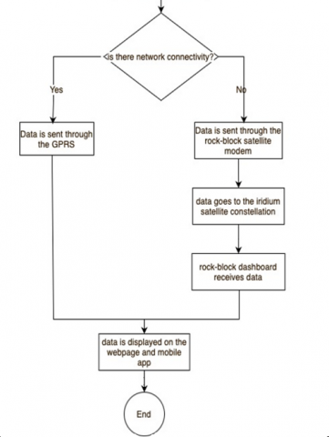
The onboard micro-controller within the head strapping devices collects the data from the temperature sensors and the magnetometer as well as the GPS and routes the data through the Lora RF module Sx1278, so once the data is in the air, the second Sx1278 in a fixed based station receives the same packet and this packet is routed to the micro-controller which we already have available. Now the controller on the base station has two network interfaces, one is the satellite modem and the second is General packet ratio service (GPRS) modem, depending on the availability of the Greedy perimeter stateless routing (GPSR) network, the controller can decide to use one of the two to route the received packet to the internet, now if there is GPRS network, the controller will maintain a Message Queuing Telemetry Transport (MQTT) connection server, so MQTT is an IOT device communication protocol that sends data between a device and server, so assuming we have a back-end server that is addressed e.g., to abc.com, the device simply sends this data over to the server there using the MQTT protocol, but should a GPRS network not be available, the data is routed through the satellite modem whose communication is between itself and the micro-controller uses a simple serial interface and the way the iridium modem we are using behaves such that any data sent over the interface to the modem, the modem picks it up and sends that data through the iridium satellite constellation, so once the data is sent over the satellite constellation, the iridium takes care of routing the data back to the web server and with that we can configure on our iridium dash board otherwise say that once we receive a data from this device simply send it through a web hock to a web server at any or given address, so we could have reconfigured the address of our web server on the iridium dash board, such that once their device send its data to their back-end cloud we will route it back to our same web server that is at abc.com. For example, once the data arrives on our back-end server, we can decide to process it by maybe saving the data in our database, and of course, once that is done, we want to route the data back to the mobile app of the end-user. Good for us, the mobile app of the end-user is using MQTT communication, which is backed up to our back-end server as well, so that is how data is routed. Figures 2 and 3 show the block diagram which summarizes the explanation. Figure 4 shows the flowchart of the working principle of the proposed system.
Figure 2. Block diagram of the proposed device (transmitter)
Figure 3. Block diagram of the proposed device (receiver)
Figure 4. Flowchart of the working principle of the proposed system
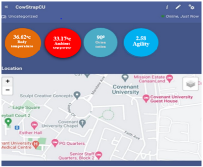
A test was conducted to verify the functionality of the electronic head-strap device. Cattle were worn the prototype of the developed head-strap and guided by a hired herder around the campus environment with the permission of appropriate authorities and the results obtained are as presented in this session. From Figure 5, you can see it was attached to the head of a cattle to collect data from the cattle. Figure 6 is the mobile application (Ismart app) used to read the result. Ismart app is a mobile application software pre-programmed platform for researchers and other commercial vendors to integrate and test their devices. The orange circle reads the results of the body temperature test; the red reads the environmental temperature; the blue reads the agility test and below that is a map showing the location of the cattle. Table 1 displays data extracted from website. All data displayed on the website is in real-time and data history is also displayed. From the various tests carried out, the mobile network functions as intended and works properly. The results of the data on the mobile app and website for the temperature sensor, the ambient temperature, the agility test, and the GPS are gotten in real time. When the satellite module was tested in the absence of GPRS, it was discovered that it takes approximately 2 minutes for the Iridium satellite to send the message to the Rockblock site and have an impact on the mobile Apps (Ismart). This reason for the delay is as novelty modelled and derived mathematically in section 4.1.
Figure 5. The device testing process
Figure 6. Mobile (Ismart) application
Table 1. Results extracted from the web site (CowStrapCU (867959034785450)0 Report)
|
Date created |
Locations |
XRAW |
YRAW |
ZRAW |
Ambient temp (℃) |
Body temp (℃) |
Latitude degree (°) |
Longitude degree (℃) |
Agility |
|
6/20/22 10:53:01 AM |
CBS GARDEN |
13311 |
-14075 |
24063 |
33.17 |
36.62 |
6.67099 |
3.16007 |
2.58 |
|
6/20/22 10:53:01 AM |
CBS GARDEN |
13567 |
-14075 |
17181 |
33.2 |
37.74 |
6.67099 |
3.16007 |
3.06 |
|
6/20/22 10:53:01 AM |
LECTURE THEATRE |
-2818 |
15878 |
26111 |
33.29 |
30.64 |
6.67203 |
3.16256 |
3.16 |
|
6/20/22 10:53:01 AM |
GUEST HOUSE |
16895 |
-10490 |
30975 |
33.14 |
37.77 |
6.67435 |
3.15947 |
2.68 |
|
6/20/22 10:53:01 AM |
UNIVERSITY STADIUM |
-9217 |
20999 |
28671 |
33.02 |
36.46 |
6.67620 |
3.16127 |
2.66 |
|
6/20/22 10:53:01 AM |
UNIVERSITY STADIUM |
-14082 |
30470 |
25599 |
32.73 |
36.39 |
6.66720 |
3.16127 |
2.73 |
|
6/20/22 10:53:01 AM |
NEW ESTATE |
5888 |
16390 |
9727 |
32.55 |
36.36 |
6.66627 |
3.15861 |
2.78 |
|
6/20/22 10:53:01 AM |
STAFF QUARTER |
4096 |
6407 |
-514 |
32.46 |
36.39 |
6.66734 |
3.16088 |
3.18 |
|
6/20/22 10:53:01 AM |
DANIEL HALL |
-13313 |
9222 |
14335 |
32.36 |
36.29 |
6.67222 |
3.15224 |
3.55 |
|
6/20/22 10:53:01 AM |
ESTHER HALL |
-16128 |
12039 |
28671 |
32.3 |
36.17 |
6.66990 |
3.15535 |
3.69 |
|
6/20/22 7:30:02 PM |
EAGLE SQUARE |
6144 |
-5882 |
-27137 |
32.14 |
36.46 |
6.67122 |
3.15479 |
3.53 |
Table 2 shows the comparative analysis of previous related works with the newly developed system. The criteria used in benchmarking include health status (ambient temperature, body temperature, magnetometer, agility), location tracking (GPS), mode of transmission (GPRS modem and Satellite modem) and mode of display (web dashboard and mobile applications). Of the twenty papers compared it was discovered that none of these papers deployed all the nine metrics as compared with our newly developed system that deployed all the nine.
The twenty publications considered in this research work were from 2017 to 2021 and are based on the same aim, objects and currency of the published work. For the health status: the ambient temperature sensors were deployed by nine (9) papers, body temperature by twenty (20), magnetometer by eight (8) and agility by one (1). While the location tracking using GPS were deployed by six (6), mode of transmission: GPRS modem by one (1) and satellite modem by one (1). Final the modes of display deployed: web dashboard application by six (6) and mobile application by eight (8). Furthermore, four (4) papers deployed only two (2) metrics of these nine (9) metrics, while four (4) papers also deployed three (3) metrics, eleven (11) papers deployed four (4) metrics and finally only one deployed five (5) metrics compared to our newly developed that deploys all the nine (9) nine parameters compared. The comparative analysis is shown in Table 2.
Table 2. Comparative analysis of previous related works with the proposed developed system using significant performances indices
|
S/N |
Authors/date |
Health status |
Location tracking |
MODE of transmission |
Mode of display |
|||||
|
Ambient temperature |
GPS |
GPRS modem |
Satellite modem |
GPS |
GPRS modem |
Satellite modem |
Web dashboard |
Mobile application |
||
|
1 |
[3] 2019 |
√ |
× |
× |
× |
× |
× |
× |
√ |
× |
|
2 |
[7] 2020 |
× |
√ |
× |
√ |
√ |
× |
√ |
× |
× |
|
3 |
[8] 2021 |
√ |
× |
× |
× |
× |
× |
× |
× |
× |
|
4 |
[4] 2020 |
× |
√ |
× |
× |
√ |
× |
× |
× |
√ |
|
5 |
[5] 2018 |
× |
√ |
× |
× |
√ |
× |
× |
√ |
× |
|
6 |
[11] 2021 |
× |
√ |
× |
× |
√ |
× |
× |
× |
× |
|
7 |
[15] 2018 |
× |
× |
× |
× |
× |
× |
× |
× |
√ |
|
8 |
[16] 2021 |
√ |
× |
× |
× |
× |
× |
× |
× |
× |
|
9 |
[17] 2020 |
× |
√ |
× |
× |
√ |
× |
× |
× |
√ |
|
10 |
[19] 2018 |
√ |
× |
× |
× |
× |
× |
× |
× |
× |
|
11 |
[29] 2018 |
√ |
√ |
× |
× |
√ |
× |
× |
× |
√ |
|
12 |
[30] 2019 |
× |
√ |
× |
× |
√ |
× |
× |
× |
× |
|
13 |
[31] 2019 |
× |
√ |
√ |
× |
√ |
√ |
× |
√ |
× |
|
14 |
[31] 2020 |
× |
× |
× |
× |
× |
× |
× |
√ |
√ |
|
15 |
[32] 2020. |
× |
√ |
× |
× |
√ |
× |
× |
× |
√ |
|
16 |
[33] 2017 |
√ |
× |
× |
× |
× |
× |
× |
× |
√ |
|
17 |
[34] 2017 |
√ |
√ |
× |
× |
√ |
× |
× |
√ |
× |
|
18 |
[35] 2018 |
√ |
× |
× |
× |
× |
× |
× |
√ |
× |
|
19 |
Proposed |
√ |
√ |
√ |
√ |
√ |
√ |
√ |
√ |
√ |
4.1 A novel mathematical model of the delay on the satellite channel used
A novel mathematical modelling of the delay on the satellite channel deployed was derived and explained as fellows. Suppose a transmitted located in free space radiate power (Pt) uniformly in all direction, thus isotropic radiation. In practice, such a situation is not possible in satellite communication because it cannot create transverse polarized electromagnetic waves. So, in practice, directional antennae are used to concentrate the energy into a given direction and its directivity. The distance between the transmitter and receiver is called R. For such a system the power density (F) at a distance R is given as shown in Eq. (1).
$\mathrm{F}=\frac{P_t G_t}{4 \pi R^2}\left(\mathrm{watt} / \mathrm{m}^2\right)$ (1)
where,
Pt=Power transmitted by the transmitter
Gt=Gain of the transmitter
R=Distance between the transmitter and receiver antennas
The power Intercepted by the receiving antenna is equal to power density (F) multiplied by the capture area (Ar) as shown in Eq. (2).
$P_r=F * A_r$ (2)
With Ar some of the signals will be absorbed and some will be reflected backwards, hence the antenna has an efficiency factor.
Let the efficiency factor of the receiving antenna be Zr (In the range of 50%-70%).
Power received (Pr) is as shown in Eq. (3).
$P_r=F A_r Z_r=\frac{P_t G_t A_r Z_r}{4 \pi R^2}$ (3)
Normally, we can show that the capture area (Ar) of the receiving antenna is directly related to the antenna gain (Gr) as shown in Eq. (4).
$G_r=\frac{4 \pi A_r Z_r}{\lambda^2}$ (4)
where,
$\lambda=\frac{c}{f}$
λ = Wave length
c=speed of light, f=operating frequency
Making Ar the subject of formulae as shown in Eq. (5).
$A_r=\frac{G_r \lambda^2}{4 \pi Z_r}$ (5)
Substituting Eq. (5) into Eq. (3), therefore
$\begin{gathered}P_r=\frac{P_t G_t Z_r}{4 \pi R^2} * \frac{G_r \lambda^2}{4 \pi Z_r} \\ P_r=P_t G_t G_r * \frac{\lambda^2}{(4 \pi R)^2}\end{gathered}$ (6)
Eq. (6) is the Friis equation of a radio link.
The link loss is the $\frac{\lambda^2}{(4 \pi R)^2}$ section and the only reason, where Pt=Pr is because of $\frac{\lambda^2}{(4 \pi R)^2}$.. The path in communication comes from here, because of the presence of R, as shown in Eq. (7).
$L_{f s}=\left(\frac{4 \pi R}{\lambda}\right)^2$ (7)
where,
$L_{f s}=\left(\frac{4 \pi R}{\lambda}\right)^2$ is the Friis’ path loss.
Substituting Eq. (7) into Eq. (6) result in Eq. (8).
$P_r=\frac{P_t G_t G_r}{L_{f s}}$ (8)
Therefore,
$P_r=\frac{\text { EIRP } * \text { Receive Antenna Gain }}{\text { Path Loss }}$
where, EIRP is the Effective Isotopic Radiation Power.
EIRP is define as radiated power with the gain of the antenna taken into consideration Eq. (8) in Decibel, is as shown in Eq. (9).
$P_r(d B)=\operatorname{EIRP}(d B)+G_r(d B)-\operatorname{Loss}(d B)$ (9)
where,
$\begin{gathered}E I R P=10 \log P_t G_t(d B) \\ G_r=10 \log \left(\frac{4 \pi A_r Z_r}{\lambda^2}\right) d B \\ L_{f s}=10 \log \left(\frac{4 \pi R}{\lambda}\right)^2 d B \\ L_{f s}=20 \log \left(\frac{4 \pi R}{\lambda}\right) d B\end{gathered}$
Eq. (9) refers to as idea situation in practice. There are other losses in satellite communication as shown in Eq. (10).
Total Loss $(L)=L_{f s}+L_{a d d}$ (10)
where, Ladd=additional Losses:
$P_r=\frac{P_t G_t G_r}{L_{f s}}=\frac{P_t G}{L_{f s}}$ (11)
where, G=Gt Gr.
Total Loss of a satellite link is given as:
$L=\frac{L_{f s}}{G_t G_r}$ (12)
Substituting Eqns. (4) and (7) into Eq. (12).
$\begin{aligned} & L=\frac{\left(\frac{4 \pi R}{\lambda}\right)^2}{\left(\frac{4 \pi A_t Z_t}{\lambda^2} * \frac{4 \pi A_r Z_r}{\lambda^2}\right)} \\ & L=\frac{4^2 \pi^2 R^2}{\lambda^2} * \frac{\lambda^2}{4 \pi A_t Z_t} * \frac{\lambda^2}{4 \pi A_r Z_r} \\ & \lambda={ }^c / f \\ & \end{aligned}$ (13)
$L=\frac{R^2 \lambda^2}{A_t Z_t A_r Z_r}$ (14)
Substituting Eq. (13) into Eq. (14),
$L=\frac{c^2 R^2}{F^2} * \frac{1}{A_t Z_t A_r Z_r}$ (15)
In some cases, Arand Zr may not be known but diameter of the antenna will be given, hence, $A_r=d_r^2$ and $A_t=d_t^2$.
$L=\left(\frac{C R}{F}\right)^2 * \frac{1}{A_r Z_r d_t^2 d_r^2}$ (16)
Eq. (16) is the Satellite link equation.
In satellite the additional losses are as shown in Eq. (17).
$L_A=L_{t a}+L_{r a}+A_{a I}+L_{\text {point }}+A_{\text {pol }}+A_{\text {rain }}$ (17)
where,
LA=Additional losses
Lta=Losses associated with transmitted antenna
Lra=Losses associated with receiver antenna
AaI=Attenuation by atmosphere and Ionosphere
Lpoint=Losses causes as a result of antenna depointing
Apol=Attenuation cause by polarization mismatch between transmitting antenna and receiving antenna
Arain=Attenuation cause by rain (cloud)
These factors in Eq. (17) vary from time to time due to weather condition a particular area.
In this research a cattle health status and location tracking system with web and mobile application feedback display was developed. Sensors on circuitry embedded in cow head-strap provides information on cattle feeding habits, cattle positions at real time, and the tracking of cattle health status. These data are transmitted via secured communication channel to applications. To verify and observe the daily activities of the cattle, the user must login to the website or mobile app. In the future, we will implement more sensors, like the heartbeat sensor and humidity sensor in the head strap device, to get more readings.
[1] InfoGuide Nigeria. (2022). Problems facing cattle farmers in Nigeria. https://infoguidenigeria.com/problems-facing-cattle-farmers/.
[2] Projecttopics. (2022). The effects of cattle rustling on socio-economic and political development of Nigeria - project topics. https://www.projecttopics.org/the-effects-of-cattle-rustling-on-socio-economic-and-political-development-of-nigeria.html.
[3] Rivas, A., Chamoso, P., González-Briones, A., Corchado, J.M. (2018). Detection of cattle using drones and convolutional neural networks. Sensors, 18(7): 2048. https://doi.org/10.3390/s18072048
[4] Unold, O., Nikodem, M., Piasecki, M., Szyc, K., Maciejewski, H., Bawiec, M., Dobrowolski, P., Zdunek, M. (2020). IoT-based cow health monitoring system. In International Conference on Computational Science, Amsterdam, The Netherlands, pp. 344-356. https://doi.org/10.1007/978-3-030-50426-7_26
[5] Blocker, A., Stuckey, E., Mari, J., Sell, S., Tuttle, G. (2018). Development of a small tracking device for cattle using IoT technology. 14th ICPA. https://www.ispag.org/session_detail?sid=555#
[6] Francis, A., Stanley, U., David, M., I Idim, A., Joshua, I. (2018). Design and implementation of a cattle grazing tracking and anti-theft alert GPS/GSM collar, leveraging on improvement in telecom and ICT infrastructure. Asian Journal of Advanced Research and Reports, 1(2): 1-9. https://doi.org/10.9734/ajarr/2018/v1i213035
[7] Priyadharsini. S, Renukasri.V, Sneha. R, Sowmiya. P.K, Swaathi. K. (2020). Wildlife animal tracking system using GPS and GSM. International Conference on Electrical, Electronics and Communication Technology, 8(17): 6-8. https://doi.org/10.17577/IJERTCONV8IS17002
[8] Okokpujie, K., Noma-Osaghae, E., John, S., Grace, K.A., Okokpujie, I. (2017). A face recognition attendance system with GSM notification. In 2017 IEEE 3rd International Conference on Electro-Technology for National Development (NIGERCON), Owerri, Nigeria, pp. 239-244. https://doi.org/10.1109/NIGERCON.2017.8281895
[9] Ojo, M.O., Viola, I., Baratta, M., Giordano, S. (2021). Practical experiences of a smart livestock location monitoring system leveraging GNSS, Lorawan and cloud services. Sensors, 22(1): 273. https://doi.org/10.3390/s22010273
[10] Stephen, U., Iorshase, A., Michael, E.B. (2019). A pervasive framework for cattle health and movement monitoring. Journal of Multidisciplinary Engineering Science and Technology, 6(5): 10125-10130.
[11] Saputra, K., Kamelia, L., Zaki, E.A. (2021). Integration of animal tracking and health monitoring systems. In IOP Conference Series: Materials Science and Engineering, 1098(4): 042075. https://doi.org/10.1088/1757-899X/1098/4/042075
[12] Dos Reis, B.R., Easton, Z., White, R.R., Fuka, D. (2021). A LoRa sensor network for monitoring pastured livestock location and activity. Translational Animal Science, 5(2): txab010. https://doi.org/10.1093/tas/txab010
[13] Bhosale, M., Pawar, S., Jagtap, P., Yewale, M.D.M. (2020). Animal health monitoring system using IoT. International Journal of Advance Scientific Research and Engineering Trends, 5(9): 99-101. http://ijasret.com/VolumeArticles/FullTextPDF/559_20.ANIMAL_HEALTH_MONITORING_SYSTEM_USING_IOT.pdf.
[14] Okokpujie, K.O., Chukwu, E.C., Noma-Osaghae, E., Okokpujie, I.P. (2018). Novel active queue management scheme for routers in wireless networks. International Journal on Communications Antenna and Propagation, 8(1): 52-61. http://dx.doi.org/10.15866/irecap.v8i1.13408
[15] Costa, D.D.S., Turco, S.H., Ramos, R.P., Silva, F.M., Freire, M.S. (2018). Electronic monitoring system for measuring heart rate and skin temperature in small ruminants. Engenharia Agrícola, 38: 166-172.
[16] Raj, P.B. (2021). GSM Based Animal Health Monitoring. International Journal of Creative Research Thoughts, 9(7): 515-520. https://ijcrt.org/viewfull.php?&p_id=IJCRT2107289.
[17] Bello, R.W., Talib, A.Z.H., Mohamed, A.S.A.B. (2020). A framework for real-time cattle monitoring using multimedia networks. International Journal of Recent Technology and Engineering, 8(5): 974-979. https://doi.org/10.35940/ijrte.E5742.018520
[18] Matthews, S.G., Miller, A.L., Plötz, T., Kyriazakis, I. (2017). Automated tracking to measure behavioural changes in pigs for health and welfare monitoring. Scientific reports, 7(1): 17582. https://doi.org/10.1038/s41598-017-17451-6
[19] Rashika, M.E., Pushpalatha, S. (2018). A Wi-Fi based animal health monitoring system. International Journal of Engineering Research & Technology (IJERT), 6(13): 1-4. https://doi.org/10.17577/IJERTCONV6IS13044
[20] Bentley, J.P. (1984). Temperature sensor characteristics and measurement system design. Journal of Physics E: Scientific Instruments, 17(6): 430. https://doi.org/10.1088/0022-3735/17/6/002
[21] Parate, M.R., Bhurane, A.A. (2022). LoRa for long-range and low-cost IoT applications. In Futuristic Research Trends and Applications of Internet of Things, pp. 71-100.
[22] Miller, J. (2018). Build a car tracking system with the SIM808 module. Maker Pro. https://maker.pro/arduino/projects/build-a-car-tracking-system-with-the-sim808-module.
[23] In-depth: Interface UBLOX NEO-6M GPS Module with Arduino. Last Minute Engineers, https://lastminuteengineers.com/neo6m-gps-arduino-tutorial/.
[24] A9G GSM/GPRS+GPS module with Arduino - getting started. https://how2electronics.com/a9g-gsm-gprs-gps-module-with-arduino/.
[25] Using the RockBLOCK iridium modem- Overview. Adafruit Learning System. https://learn.adafruit.com/using-the-rockblock-iridium-modem?view=all.
[26] Bhatia, S.C., Mangla, P. (2020). Wind Energy. Woodhead Publihsing India Pvt Limited. https://doi.org/10.1016/B978-1-78242-269-3.50008-5
[27] What is a jumper wire. Sparkfun Education. https://blog.sparkfuneducation.com/what-is-jumper-wire.
[28] Triple-axis magnetometer (compass) board - HMC5883L. Sensors, Accel, Gyro, and Magnetometers, Magnetometers. https://www.adafruit.com/product/1746.
[29] Noma-Osaghae, E., Okokpujie, K.O., Ndujiuba, C.U., Olatunji, O., Okokpujie, I.P. (2018). Epidemic alert system: A web-based grassroots model. International Journal of Electrical and Computer Engineering, 8(5): 3809-3828.
[30] Bhatt, E.N.D., Kc, S.K., Rai, S., Bastakoti, J. (2019). GPS based animal tracking with SMS Alert. In 2nd International Conference on Engineering and Technology; KEC Conference-2019, Dhapakhel, Lalitpur, Nepal. http://kec.edu.np/wp-content/uploads/2020/01/Paper_23.pdf.
[31] Kalaivani, S., Anitha, R., Anusooya, S., Shilpa, J. (2019). IoT based physical condition screening system for animals. International Journal of Recent Technology and Engineering (IJRTE), 8(2S5): 231-234. https://doi.org/10.35940/ijrte.B1047.0782S519
[32] Almazan, V.K.B., Mahipus, F.I.B., Santos, J.R.M., Samonte, M.J.C. (2020). CAHM: Companion animal health monitoring system. In Proceedings of the 2020 11th International Conference on E-Education, E-Business, E-Management, and E-Learning, Osaka, Japan, pp. 417-421. https://doi.org/10.1145/3377571.3377641
[33] Swain, K.B., Mahato, S., Patro, M., Pattnayak, S.K. (2017). Cattle health monitoring system using Arduino and LabVIEW for early detection of diseases. In 2017 Third International Conference on Sensing, Signal Processing and Security (ICSSS), pp. 79-82.
[34] Aswini, D., Santhya, S., Nandheni, T.S., Sukirthini, N. (2017). Cattle health and environment monitoring system. International Research Journal of Engineering and Technology, 4(3): 1899-1903.
[35] Vijayashree, B.R., Sunilkumar, R., Medhavi, S.C., Ezhilarasan, K. (2018). Emergency detection and monitoring daily routine of cattle using IoT. International Journal of Computer Applications, 179(28): 21-23.