Bernard A. Adaramola*![]() | Joseph F. Kayode
| Joseph F. Kayode![]() | Sunday A. Afolalu
| Sunday A. Afolalu![]() | Oluwasina L. Rominiyi
| Oluwasina L. Rominiyi![]() | Imhade P. Okokpujie
| Imhade P. Okokpujie![]() | Omolayo M. Ikumapayi
| Omolayo M. Ikumapayi![]()
© 2023 IIETA. This article is published by IIETA and is licensed under the CC BY 4.0 license (http://creativecommons.org/licenses/by/4.0/).
OPEN ACCESS
The Bernoulli’s apparatus, a pivotal tool for exploring fluid flow characteristics within piping architecture, has been designed with an emphasis on usability, reliability, affordability, and material accessibility. This device, encompassing Venturimeters, pressure gauges, pipes, and capillary tubes, was fabricated and assembled within the central Engineering workshop at ABUAD. The apparatus was designed to enable the utilization of pressure gauges for the measurement of pressure head within pipes. Experimental procedures entailed the examination of varied water flow rates, with pressure head and volume measurements taken over 20-second intervals. The Reynolds's number was calculated, utilizing the viscosity and density of water, alongside the pipe diameter and velocity, to classify the fluid flow as either laminar, transitional, or turbulent. Results indicated an escalation in Reynolds number concurrent with the flow rate. For each discharge, Reynolds's numbers and flow categorizations were determined. The initial discharge yielded a Reynolds number approximating 3819, signifying transitional flow. Subsequent discharges demonstrated Reynolds numbers of approximately 5347, 7129, 8912, 10439, and 12371, respectively, indicative of turbulent flow. Turbulent flows are characterized by high velocities, unpredictable variations in flow magnitude and direction, and erratic alterations in pressure.
flow velocity, discharge, laminar flow, transitional flow, turbulent flow, Reynolds number, Venturimeter
Bernoulli's apparatus is a fundamental experimental device in fluid mechanics, allowing students to verify Bernoulli's equation and understand fluid friction, pressure, and velocity. It is a challenging task due to its complexity and importation for experimental purposes [1]. Utilizing engineering knowledge and effort, students can construct complex devices, gaining a deeper understanding of engineering apparatus construction and fostering further improvement. According to the studies [2, 3], the purpose of using Bernoulli's apparatus is to validate Bernoulli's equation and observe the correlation between pressure head and kinetic head, as well as understand the conditions under which it is applicable.
The apparatus also helps visualize changes in the energy grade line and the hydraulic grade line. It achieves this by demonstrating the variations in manometric head, velocity, flow rate, and the different losses that occur in flow through a Venturimeter [4]. The Venturimeter includes a rectangular section, horizontal flow, a contracting section with a throat of smaller cross-sectional area, and an expanding section.
This research intends to develop a Bernoulli apparatus for the investigation of fluid flow characteristics known as the Reynolds number in liquids. The fluid flow is laminar, transitional, or turbulent depending on this value. While turbulent flow occurs when liquid moves chaotically, making predictions about its flow challenging, laminar flow happens whenever liquid flows smoothly in a predictable manner without overlapping adjacent layers [5]. Vibrations brought on by turbulent flows can hasten a system's failure by causing early system wear. The device is merely an accessory that uses the hydraulic bench as both its water source and reservoir, so it may be attached to one.
Limjuco et al. [6] asserted that due to the growing number of science and engineering students there is a need for additional laboratory equipment and instruments. This is necessary to facilitate learning, which prompted the production of extra laboratory equipment. The Bernoulli apparatus is particularly useful for determining the Reynolds number in experiments due to its simple design, ease of construction, reliability, portability, and user-friendliness [7].
There is an increasing demand to classify flow types (laminar, turbulent, and transitional) due to their relevance in various machinery and energy production equipment that involve fluids. To support learning and facilitate the examination of fluid turbulence, additional laboratory equipment is required. This equipment aids in identifying and designing fluid flow systems, as well as determining the appropriate type of fluid for such systems. The Bernoulli's Apparatus [8] offers a practical solution as it is characterized by its simple design, ease of fabrication, portability, and suitability for conducting experiments to determine Reynolds number and transitional flow.
1.1 Reynolds number
The Reynolds number (Re) is a crucial dimensionless quantity in fluid mechanics, predicting flow patterns in various situations. Low Reynolds numbers lead to laminar flow, while high Reynolds numbers cause turbulence due to fluid speed and direction differences, causing eddy currents and increasing cavitation risk. Its applications include pipe flow and aircraft wing passage Flow around a hemisphere-cylinder at high angle of attack and low Reynolds number [9].
The Reynolds number is a tool for predicting flow transitions from laminar to turbulent, scaling similar situations, and predicting turbulence onset. It helps predict fluid behavior on a larger scale, affecting meteorological and climatological effects [10].
The Reynolds number is defined as,
$R e=\frac{\rho v l}{\mu}=\frac{v l}{v}$ (1)
where, $\rho$ is the density of the fluid (SI units: kg/m3); $v$ is the velocity of the fluid with respect to the object (m/s); $l$ is a characteristic linear dimension (m); $\mu$ is the dynamic viscosity of the fluid (Pas or Ns/m2 or kg/ms) and $v$ is the kinematic viscosity of the fluid (m2/s).
1.2 Laminar versus turbulent fluid flow
Two categories of viscous flows exist:
Wilfred et al. [11] developed a fast technique for modelling convective displacements in large-scale reservoirs. They integrated 10 solutions with streamtubes or streamlines, constructing approximate solutions in two and three dimensions.
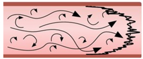
Figure 1 shows the relation between laminar flow, transitional flow and turbulent flow regimes, while Figure 2 presents the three flow regimes.
Figure 1. Relation between laminar flow, transitional flow and turbulent flow regimes [12]
(a) Laminar flow
(b) Transitional flow
(c) Turbulent flow
Figure 2. Laminar, transitional and turbulent flow [13]
Laminar flow, also known as streamline flow, is a fluid dynamics regime where fluid flows in parallel layers without disruption. It is characterized by high momentum diffusion and low momentum convection, with particles moving in straight lines parallel to a solid surface. Fluid flow through closed channels, like pipes or flat plates, can be classified as laminar flow or turbulent flow. Laminar flow occurs at lower velocities, below a threshold for turbulent flow, while turbulent flow is less orderly and characterized by eddies or small particles causing lateral mixing. Laminar flow is smooth in non-scientific terms [12].
Turbulence is a pattern of fluid motion with chaotic changes in pressure and velocity, unlike a flow regime [13]. It is common in everyday phenomena and is caused by excessive kinetic energy in fluid flows. Turbulence is easier to create in low viscosity fluids but more challenging in highly viscous fluids. Turbulent flow involves unsteady vortices interacting, increasing drag due to friction effects. This effect can be exploited by aerodynamic spoilers on aircraft, increasing drag and reducing lift. The Reynolds number predicts turbulence onset, balancing kinetic energy and viscous damping. Turbulent flows have specific characteristics. Turbulent flows are irregular, requiring statistical treatment rather than deterministic approaches. They are chaotic, but not all chaotic flows are turbulent.
Diffusivity accelerates homogenization and increases mass, momentum, and energy transports in turbulent flows. Turbulent flow involves irregular fluctuations or mixing in fluid, unlike laminar flow, which moves in smooth paths or layers. It is common in wind and river flows, with air or water swirling and eddies while its bulk moves along a specific direction. The boundary layer or laminar sub-layer is always present in turbulent flow. Turbulent flow occurs in various environments, including blood, oil, lava, and ocean currents [14].
1.3 Bernoulli’s apparatus
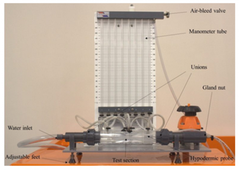
The Bernoulli test apparatus consists of a converging-diverging duct, manometers for pressure head measurement, and a hypodermic probe for total head measurement. The manometer for Bernoulli's Experiment, Flow around a Bend, and Air Flow in Pipes Apparatus is made of transparent acrylic tubes, has a height of 400 mm, 1 mm graduations, and an adjustable water reservoir. It features pressure ports at the top. The Venturimeter regulates water flow without turbulence upstream. Students use a hand-pump to adjust water levels in manometer tubes. The Armfield F1-15 Bernoulli's Apparatus in Figure 3 is a rectangular duct with a convergent-divergent shape, compatible with Cussons' Inlet and Outlet Tanks [15]. The apparatus features a dye injection system for introducing a single filament, demonstrating laminar and turbulent flow regimes, with adjustable differential head and visual representation.
Figure 3. Armfield F1-15 Bernoulli’s apparatus test equipment [7]
1.4 Venturimeter
A Venturimeter measures fluid flow in pipes using Bernoulli's equation principles. It reduces cross-sectional area, creating a pressure difference, which is measured using a manometer. The inlet area increases fluid velocity, causing a decrease in pressure, which can be measured using Bernoulli's equation and the discharge formula. The Venturimeter's Coefficient of discharge ranges from 0.96 to 0.98.
$\mathrm{Q}_{\mathrm{act}}=\mathrm{C}_{\mathrm{d}} * \frac{\mathrm{A}_1{ }^* \mathrm{~A}_2}{\sqrt{\mathrm{A}_1{ }^2-\mathrm{A}_2{ }^2}} * \sqrt{2 \mathrm{gh}}$ (2)
A Venturimeter consists of three components: a tapered converging section, a throat with the smallest cross-sectional area, and a diverging section where fluid starts to spread out as shown in Figure 4.
The Venturimeter measures fluid flow rate in pipes using pressure difference between inlet and throat cross-sectional areas. The fluid converges at the inlet section, reaching the throat with the smallest cross-sectional area. The fluid enters the throat, increasing velocity and decreasing pressure, creating a pressure difference between inlet and throat sections. A manometer measures this difference, which is used to calculate the fluid's flow rate through the pipe.
Figure 4. The F1-hydraulic bench Ventrimeter [15]
1.5 Bernoulli’s equation
If friction losses are neglected and no energy is added to, or taken from a piping system, the total head, H, which is the sum of the elevation head, the pressure head and the velocity head, will be constant for any point of fluid streamline.
$\mathrm{Z}_1+\frac{\mathrm{P}_1}{\rho_1 \mathrm{~g}}+\frac{\mathrm{V}_1{ }^2}{2 \mathrm{~g}}=\mathrm{Z}_2+\frac{\mathrm{P}_2}{\mathrm{P}_2 \mathrm{~g}}+\frac{\mathrm{V}_2{ }^2}{2 \mathrm{~g}}$ (3)
This is the expression of law of head conservation to the flow of fluid in a conduit or streamline and is known as Bernoulli equation [15].
1.6 Related works
The aviation industry is increasingly seeking eco-friendly aircraft due to rising air traffic and environmental concerns. Hybrid laminar flow control (HLFC) technology, developed for commercial aircraft, offers potential in achieving these goals. Extensive research has advanced integration, safety, and maintenance considerations. Spelay et al. [16] review recent research on HLFC systems in the US and Europe, identifying successful and out-dated approaches, and estimating weight, power consumption, performance, maintenance, and subsystem definitions.
Le Clainche et al. [17] investigated "horn" vortices generation in 3-dimensional DNS and PIV research on hemisphere-cylinder separated flow phenomena. Critical-point theory and analysis techniques like POD and DMD were utilized to examine flow structures. Results from experiments and computer simulations point to a dominating frequency connected to von Karman vortex shedding and modes connected to flow separation. By investigating the body surface topology, critical-point theory can identify flow patterns such separation bubbles, horn vortices, and leeward vortices. The frequency connected to these structures is measured [18].
Krishnan et al. [19] conducted research with a focus on the significance of comprehending kinetic theory, Bernoulli's principle, and molecular models for fluid behaviour. To help students understand ideal gas behaviour and fluid dynamics, they created experimental activities and questions. The research of Pualinus et al. [20] showed that comprehension of Bernoulli's Principle requires a mental knowledge of kinetic theory, specifically pressure-particle collisions. In the spring of 2013, general physics students participated in a multi-representational lab that was created and tested to address these findings. The lab dramatically increased students' knowledge of the Bernoulli Principle and fluid statics. Overall, the study demonstrated the value of using many representations to help students better understand key ideas and the need for precise molecular models [21].
Ekong [22] developed a semi-empirical correlation to accurately predict low Reynolds number Pitot tube behaviour. The correlation considers a viscous factor that Bernoulli's Equation does not consider. It predicts $C_p$ with more precision than previous correlations based on outer diameter. The correlation provides smoother transitions at both ends of the low Reynolds range and converges asymptotically with Bernoulli's equation at the critical transition $(\operatorname{Re} \approx 35)$ and with a Stokes Law analogy at the low end $(\operatorname{Re}<10)$.
2.1 Materials
For the construction of the Bernoulli apparatus, materials including 1 inch pipe fittings, 1 inch elbows or bends, reducers, steel plates, 1 inch hose, capillary tubes, angle iron, pipes, clips, unions, and other components like Teflon Venturimeters, Pressure gauges, and Gate valves were utilized.
2.2 Methods
The procedure used for constructing the Bernoulli apparatus includes design calculations, SolidWorks rendering, fabrication, and equipment testing. The F1-hydraulic bench supplies water to the apparatus through an inlet pipe. The flow of water is controlled by the gate valve, and pressure gauges are used to measure and record the pressure buildup through capillary tubes and a hose. The conservation of mass requires that the fluid moves in a way that ensures constant velocity and density over the area. In the case of steady flow through a duct, the inflow and outflow are one-dimensional, and the velocity and density remain constant over the area. As there is no flow through the side walls of the duct, the mass that enters through the inlet is equal to the mass that exits through the outlet.
2.2.1 Venturimeter structural design
The following formula was utilized to determine the taper angle at which the taper turning operation would be performed on the Venturimeter.
$\theta=\frac{(\mathrm{D}-\mathrm{d})}{2 \mathrm{~L}}$ (4)
where, D = 25 mm = 2.5 cm
d = 15 mm = 1.5 cm
${Ǿ}=\tan ^{-1} \theta$ (5)
where, $Ǿ$ is the taper angle.
$\theta=\frac{2.5-1.5}{12 \times 2}=\frac{1}{24}=0.041667$
$\dot{\varnothing}=\tan ^{-1}(0.041667)=2.39$
Diameter of Pipe, D = 25 mm = 0.025 m
Area of pipe, $\mathrm{a}=\frac{\pi D^2}{4}=\frac{\pi * 0.025^2}{4}=0.000491 \mathrm{~m}^2$
Dynamic viscosity, $\mu=0.001 \mathrm{Ns} / \mathrm{m}^2$
Density of fluid (water), $\rho=1000 \mathrm{kgm}^{-3}$
If $\mathrm{Re}<2000$, the flow is laminar. $\mathrm{Re}$ is in between 2000 and 4000 , the flow is transitional. If $\mathrm{Re}$ is $>4000$, the flow is turbulent.
To convert from Bar to meter head (pressure head), 0.09804139432 bar $=1$ meter head.
$\therefore 1$ bar $=\frac{1}{0.0984139432}=10.199773373 \mathrm{~m}$. head
To convert from litres to cubic meters $\left(\mathrm{m}^3\right)$,
1 litre = 0.001m3
To evaluate Reynolds's number, the following parameters were considered:
Discharge Formula:
It is a dimensional quantity.
Discharge, $\mathrm{Q}=\frac{A \Delta h}{\Delta t}$ or $\mathrm{Q}=\frac{V}{t}\left(\mathrm{~m}^3 / \mathrm{s}\right)$ (6)
Velocity, $\mathrm{v}=\frac{Q}{a}(\mathrm{~m} / \mathrm{s})$ (7)
To evaluate Reynolds's number, the following parameters were considered:
$\rho=$ density of water
$\mathrm{D}=$ diameter of pipe
$\mathrm{a}=$ area of pipe
$\mathrm{V}=$ Volume of water collected in reservoir
$\mathrm{h}=$ head of water in meters
$\mu=$ Dynamic viscosity
$\mathrm{Q}=$ Discharge
$\mathrm{v}=$ velocity of water
$\mathrm{A}=$ Area of reservoir
Reynolds's number, $\operatorname{Re}=\frac{\rho V D}{\mu}$ from (1)
Depth of water collected in the collecting tank,
$\Delta h=\mathrm{h}_1-\mathrm{h}_2(\mathrm{~m})$ (8)
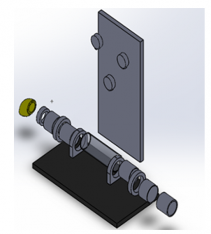
The SolidWorks rendering of the designed Venturimeter and the Venturi installed on steel plates are shown in Figure 5 and Figure 6 respectively.
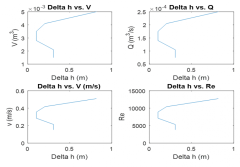
The result of $\Delta h$ is shown in Table 1, which was used to plot graphs presented in Figure 7 and Figure 8.
Table 1. Experimental values of parameters
|
S/N |
h1 (m) |
h2 (m) |
$\Delta \boldsymbol{h}$ (m) |
T (s) |
V (m3) |
Q (m3/s) |
v (m/s) |
Re |
|
1 |
1.2239 |
1.5299 |
0.306 |
20 |
0.0015 |
0.000075 |
0.1530 |
3819.2234 |
|
2 |
2.5499 |
2.8559 |
0.306 |
20 |
0.0021 |
0.000105 |
0.2140 |
5346.9127 |
|
3 |
3.0599 |
3.1619 |
0.102 |
20 |
0.0028 |
0.00014 |
0.2851 |
7129.2170 |
|
4 |
3.9779 |
4.0799 |
0.102 |
20 |
0.0035 |
0.000175 |
0.3565 |
8911.5213 |
|
5 |
4.6919 |
4.8958 |
0.204 |
20 |
0.0041 |
0.000205 |
0.4180 |
10439.2106 |
|
6 |
5.2019 |
6.0178 |
0.816 |
20 |
0.005 |
0.00025 |
0.5092 |
12730.7447 |
2.2.2 Solidworks rendering
Figure 5. Venturimeter solid works rendering
Figure 6. Venturi installed on steel plates
2.2.3 Fabrication
The Bernoulli’s apparatus used in the experiment is a rectangular Venturi duct 40×30 mm constructed from Teflon material, which underwent an internal taper turning process. This process gradually reduced the diameter of the Venturimeter from 25 mm at both the inlet and outlet sections to 15 mm at the throat. A clearance of 30 mm was provided on both ends of the Venturimeter for pipe fitting on front and rear walls of transparent scales. The inlet section of the Venturimeter had a length of 20 mm, including a tapered length of 40 mm. The throat section had a diameter of 15 mm and a length of 10 mm as shown in Figure 7.
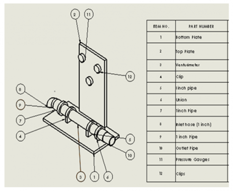
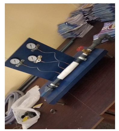
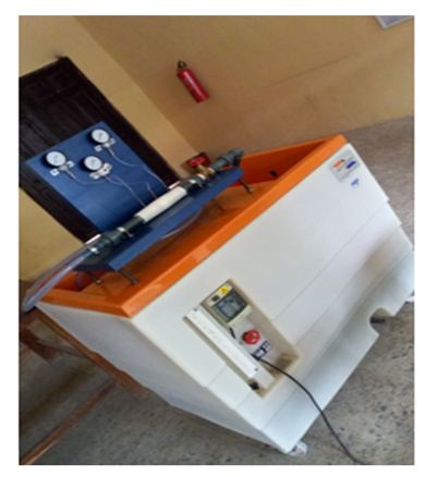
Pressure taps were connected to the 18 tube manometer fitted along the upper wall with a total head probe along the axis of the duct connected to the blower outlet by a hose. Pressure tapings were drilled into the Venturimeter at the inlet, throat, and outlet sections. The diameter of the Venturimeter at the pressure tapings was 23 mm at both the inlet and outlet sections, and 15 mm at the throat. Appendix 1 show the Bernoulli's apparatus assembly while Appendix 2 depicts the completed Bernoulli’s apparatus installed on Hydraulic Bench.
2.2.4 Experimental test
A study was performed using a specially designed Bernoulli apparatus to determine the Reynolds's number and classify the flow regime (laminar, transitional, or turbulent). The experiment followed these steps:
The pipe's diameter was measured at room temperature. The inlet valve and the control (gate valve) on the apparatus were both closed as a result of the hydraulic bench was powered. To maintain a constant water level in the tank and indicate equal incoming and outgoing discharge, the inlet valve was opened and the control valve was lightly adjusted. Over a specific time frame, the discharge was measured. Six times the entire process was conducted. The flow rate was then computed for velocity for analysis.
3.1 Results
The results of experiments conducted using a specially designed Bernoulli apparatus presents Reynolds’s number and classify the flow regime (laminar, transitional, or turbulent).
Reynolds's numbers and flow categorize each discharge. In this experiment, the first discharge had a $\operatorname{Re} \approx 3819$, indicating transitional flow. The second, third, fourth, fifth, and sixth discharges had $R e \approx 5347,7129,8912,10439$, and 12371 , respectively, indicating turbulent flow. Turbulent flow is characterized by high velocities, continuous changes in magnitude and direction of flow, and chaotic changes in pressure. The variations in manometric heights with time, volumetric change, discharge, and velocity changes with Reynolds's numbers are shown in Table 1.
Figure 7. Change in height versus Reynolds number, volume, discharge, and velocity
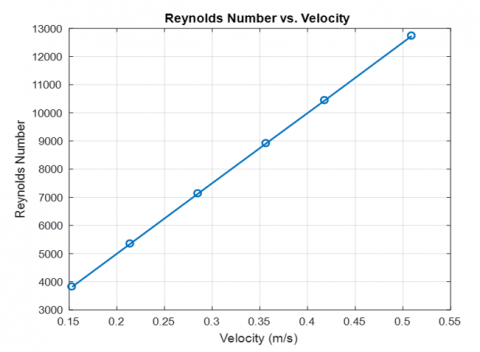
Figure 8. Reynolds number versus velocity graph
Four subplots of a graphical representation generated using MATLAB are shown in Figure 7. Each subplot depicts a distinct relationship using the given data. The $\mathrm{x}$-axis of all plots represents the variable "$\Delta \mathrm{h}$" expressed in meters. The $\mathrm{y}$-axes show several numbers like"$V\left(\mathrm{~m}^3\right)$," "Q $\left(\mathrm{m}^3 / \mathrm{s}\right)$", "$v$ (m/s)," and "Re".
3.2 Discussion
This code creates vectors for each variable in the data table, and then plots the Reynolds's number (Re) on the y-axis and the flow velocity (v) on the x-axis, using a scatter plot. The resulting graph should show how the Reynolds's number increases as the flow velocity increases.
The regime of flow was determined based on the Reynolds's number $(R e)$ value, which changes with velocity as shown in Figure 8. It's important to note that for flows with a Reynolds's number, $R e<2000$ is considered laminar when, while with Reynolds's numbers between 2000 and 4000 i.e. $2000>\operatorname{Re}$ $<4000$ are transitional., and flows exceeding with $R e>4000$ are considered turbulent.
Here are the Reynolds's numbers and flow categorizations for each discharge.
First discharge: Reynolds's number ≈ 3819, indicating transitional flow. Second discharge: Reynolds's number ≈ 5347, indicating turbulent flow. Third discharge: Reynolds's number ≈ 7129, indicating turbulent flow. Fourth discharge: Reynolds's number ≈ 8912, indicating turbulent flow. Fifth discharge: Reynolds's number ≈ 10439, indicating turbulent flow. Sixth discharge: Reynolds's number ≈ 12371, indicating turbulent flow.
These flows typically involve high velocities and exhibit continuous changes in both magnitude and direction. Additionally, they are characterized by chaotic variations in pressure.
The small-scale Bernoulli's apparatus development framework presented in this work is designed for laboratory use. The purpose of the apparatus is to investigate various fluid flow regimes (laminar, transitional, or turbulent) and carry out experiments that can determine the Reynolds number. The apparatus is constructed using locally available materials, which makes it cost-effective and suitable for use in both research laboratories and educational institutions. The Venturimeter is properly aligned with the pipe fittings to reduce turbulence and ensure smooth operation. The use of manometer tubes instead of gauges simplifies the measurement of pressure head values. Furthermore, probes could be added to the apparatus to verify Bernoulli's equation and to determine the total static head and head loss due to friction.
The recommendations for improving Bernoulli's apparatus include adding a static head probe, using manometer tubes for pressure measurements, and ensuring proper alignment of the Venturimeter. These changes will enhance the apparatus's functionality and accuracy, leading to more reliable experimental results and a better understanding of fluid dynamics principles. The addition of these measures will ensure accurate and reliable results.
The ABUAD Central Workshop and Thermofluid Laboratory at Afe Babalola University in Ado, Nigeria, where the fabrication and tests were conducted, are acknowledged by the authors.
|
$\mathrm{Q}_{\text {act }}$ |
actual discharge, $\mathrm{m}^3 / \mathrm{s}$ |
|
$\mathrm{C}_{\mathrm{d}}$ |
coefficient of discharge, dimensionless |
|
$\mathrm{G}$ |
gravitational acceleration, m.s-2 |
|
$\mathrm{D}$ |
diameter of pipe, $m^2$ |
|
$\mathrm{A}$ |
area of pipe, $m^2$ |
|
$\mathrm{V}$ |
velocity of water, $\mathrm{m} / \mathrm{s}$ |
|
$\mathrm{A}$ |
area of reservoir, $m^2$ |
|
$R e$ |
Reynolds number, dimensionless |
|
$\mathrm{H}$ |
height, m |
|
Greek symbols |
|
|
$P$ |
density of fluid, $\mathrm{kg} \cdot \mathrm{m}^{-3}$ |
|
$\mathrm{N}$ |
kinematic viscosity of the fluid, $\mathrm{m}^2 / \mathrm{s}$ |
|
$\beta$ |
thermal expansion coefficient, $\mathrm{K}^{-1}$ |
|
$\mu$ |
dynamic viscosity, $\mathrm{kg} \cdot \mathrm{m}^{-1} \cdot \mathrm{s}^{-1}$ |
|
$\Theta$ |
Angle $^{\circ}$ |
|
Subscripts |
|
|
D |
Discharge |
|
1,2 |
area 1 and 2 |
|
Act |
Actual |
[1] Enamul Hasan Kamal, S.Y.E.D., Sakib, N., Islam, R. (2012). Design and construction of Bernoullis apparatus Doctoral dissertation, Department of Mechanical. Engineering, Military Institute of Science &Technology.
[2] Traum, M.J., Mendoza Zambrano, L.E. (2021). A fluids experiment for remote learners to test the unsteady Bernoulli equation using a burette. ASME International Mechanical Engineering Congress and Exposition, 85659: V009T09A014. https://doi.org/10.1115/IMECE2021-70018
[3] Alexa, V., Kiss, I., Raţiu, S. (2014). Verification of Bernoulli law using the software autodesk simulation CFD. Analecta Technica Szegedinensia, 8(2): 120-127. https://doi.org/10.14232/analecta.2014.2.120-127
[4] Mykhailyshyn, R., Xiao, J. (2022). Influence of inlet parameters on power characteristics of Bernoulli gripping devices for industrial robots. Applied Sciences, 12(14): 7074. https://doi.org/10.3390/app12147074
[5] Marciotto, E.R. (2016). Classic Bernoulli’s principle derivation and its working hypotheses. Physics Education, 51(4): 045005. https://doi.org/10.1088/0031-9120/51/4/045005
[6] Limjuco, R.P., Glover, F.F.G., Mendez, I.M. (2012). Low-cost Venturi meter: Understanding Bernoulli’s equation rough a demonstration. IAMURE International Journal of Mathematics Engineering & Technology 2(1). https://doi.org/10.7718/iamure.ijmet.v2i1.249
[7] Mansor, M.F., Sam, R., Masrie, M., Janin, Z. (2017). Design and development of flexible end- effector based on Bernoulli principle. 2017 IEEE 13th International Colloquium on Signal Processing & its Applications (CSPA), Penang, Malaysia, pp. 318-322. https://doi.org/10.1109/CSPA.2017.8064973
[8] Brun, X.F., Melkote, S.N. (2009). Modeling and prediction of the flow, pressure, and holding forcegenerated by a Bernoulli handling device. Journal of Manufacturing Science and Engineering, 131(3): 031018. https://doi.org/10.1115/1.3139222
[9] Barklage, A., Römer, U., Bertram, A., Bekemeyer, P., Himisch, J., Radespiel, R., Badrya, C. (2022). Analysis and uncertainty quantification of a hybrid laminar flow control system. AIAA Journal, 60(10): 5735-5749. https://doi.org/10.2514/1.J061745
[10] Chammem, T., Mhiri, H., Vauquelin, O. (2013). Experimental and computational investigation of Reynolds number effect on the longitudinal ventilation in large enclosure of twin inclined jets. Building and Environment, 67: 87-96. https://doi.org/10.1016/j.buildenv.2013.05.009
[11] Wilfred, C.C., Nwigbo, S.C., Nwankwo, T.A., Chukwunonso, O.U. (2021). Design and fabrication of a classical fibre glass laboratory Venturimeter apparatus. International Journal of Innovative Science and Research Technology, 6(6): 557-567.
[12] Bergthorson, J.M., Sone, K., Mattner, T.W., Dimotakis, P.E., Goodwin, D.G., Meiron, D.I. (2005). Impinging laminar jets at moderate Reynolds numbers and separation distances. Physical Review E, 72(6): 066307. https://doi.org/10.1103/PhysRevE.72.066307
[13] Abd, H.M., Alomar, O.R., Mohamed, I.A. (2019). Effects of varying orifice diameter and Reynolds number on discharge coefficient and wall pressure. Flow Measurement and Instrumentation, 65: 219-226. https://doi.org/10.1016/j.flowmeasinst.2019.01.004
[14] Chakrabarti, S. (2015). A novel experimental setup to study the Hagen–Poiseuille and Bernoulli equations for a gas and determination of the viscosity of air. European Journal of Physics, 36(6): 065046 https://doi.org/10.1088/0143-0807/36/6/065046
[15] Misaiko, K., Vesenka, J. (2013). Connecting the dots: Links between Kinetic theory and Bernoulli's principle. Physics Education Research Conference (Part of the PER Conference Series) (Portland, United States), 52: 257-260. https://doi.org/10.1119/perc.2013.pr.052
[16] Spelay, R.B., Adane, K.F., Sanders, R.S., Sumner, R.J., Gillies, R.G. (2015). The effect of low Reynolds number flows on pitot tube measurements. Flow Measurement and Instrumentation, 45: 247-254. https://doi.org/10.1016/j.flowmeasinst.2015.06.008
[17] Le Clainche, S., Li, J.I., Theofilis, V. Soria, J. (2015). Flow around a hemisphere-cylinder at high angle of attack and low Reynolds number. Part I: Experimental and numerical investigation. Aerospace Science and Technology, 44: 77-87. https://doi.org/10.1016/j.ast.2014.03.017
[18] Dede, E.M., Zhou, Y., Tambo, T., Zhou, F., Lohan, D.J., Nomura, T. (2022). Measurement of low Reynolds number flow emanating from a Turing pattern microchannel array using a modified Bernoulli equation technique. Experimental Thermal and Fluid Science, 139: 110722. https://doi.org/10.1016/j.expthermflusci.2022.110722
[19] Krishnan, K.S.G., Bertram, O., Seibel, O. (2017). Review of hybrid laminar flow control systems. Progress in Aerospace Sciences, 93: 24-52. https://doi.org/10.1016/j.paerosci.2017.05.005
[20] Pualinus, A.P., Agwu, U.L., Sunday, U.L. (2015). Efficiency of locally fabricated venturi meter marched with ISO standard. International Journal of Emerging Technology and Advanced Engineering, 5(11): 232-241.
[21] Johnson, I., Okeoma, T.F., Stephen, A.T. (2023). Development and test performance of a bench top venturi tube. Journal of Science and Technology Research, 5(2): 296-304. https://doi.org/10.5281/zenodo.8020268
[22] Ekong, G.I. (2020). The performance analysis of a Venturimeter flow rig. International Journal of Engineering Science Invention, 9(5): 14-23.