Oussama Belaroussi* | Amel Terki | Abdelkarim Ammar | Kalinin Vyaslav Fedorovich
© 2022 IIETA. This article is published by IIETA and is licensed under the CC BY 4.0 license (http://creativecommons.org/licenses/by/4.0/).
OPEN ACCESS
Because water extraction from wells accounts for the bulk of energy consumption in irrigation operations globally, the sustainability and profitability of irrigation are strongly reliant on the energy efficiency of the pumping system. A technique that studies and improves the performance of motors used in well pumping systems is reported in this body of research as having been undertaken. In a similar manner, an experimental investigation of the energy efficiency of two modern systems of induction motor control has been carried out. According to the results, proper control performance is critical to achieving improvements in energy and efficiency. Using DTC-SVM for IM, the purpose of this study is to demonstrate a prototype of a pumping system that is powered by solar energy in the presence of changing radiation levels. Real-time MATLAB/Simulink simulations are used in conjunction with a dSpace 1104 board to carry out the hardware implementation.
pumping system, induction motor, centrifugal pump, direct torque control, space vector modulation, DTC-SVM
An induction motor (IM), and particularly a squirrel cage induction machine, has a number of advantages over a direct current (DC) machine. These advantages may be broken down into three categories. Because of the low costs associated with its production, as well as its wide speed range, high efficiency, outstanding resilience, and little maintenance needs, IM is a well-liked alternative. The use of IMs may be found in a wide variety of residential, commercial, industrial, and utility applications. Their management is carefully examined for a wide variety of applications, each of which has unique management requirements [1]. The nonlinear model that governs speed, stator flux, and torque [2] makes the IM a little more difficult to understand than it would otherwise be. Induction motor drives use a technique of control known as vector control or rotor field-focused control called field-oriented control. The key advantage of using this control mechanism as opposed to scalar-controlled drives is the speed with which it can respond dynamically. The impact of coupling that exists between torque and flux is managed by decoupling control, also known as rotor flux orientation control [3, 4]. This control allows torque and flux to be independently adjusted. This control approach has the advantage of being quite successful in terms of the amount of time it takes for the torque to respond over a wide variety of speed control ranges [5]. Nevertheless, this approach is susceptible to fluctuations in the parameters of the IM as well as disruptions in the external load [6]. Direct torque control, often known as DTC, was proposed as a solution to alleviate these drawbacks [7]. It offers a high level of resilience to changes in IM parameters. The use of hysteresis controllers, on the other hand, causes significant ripples in the electromagnetic torque and in the stator flux, especially at low speeds. These ripples lead to mechanical vibration and additional noise. In addition, because of the variation in high frequency, the total harmonic distortion (THD) of the stator current will increase forward [8]. In order to attenuate these waves, multilevel inverters, also known as MLIs, are used [9]. It was stated that there is a space vector pulse width modulation that may reduce ripples in flux and torque [10]. The speed controller utilized in DTC-SVM-IM exhibits performance when parameters are altered and unsatisfactory rejection when the load torque and disturbances are applied, necessitating the usage of robust control [11]. For this purpose, the DTC-SVM control strategy (without the use of hysteresis controllers) is recommended in order to obtain a selection table that permits the optimal selection of the voltage vector sequence to be applied to the motor while respecting the constraints on flux and electromagnetic torque. This enables us to regulate the torque directly without the need for hysteresis controllers, resulting in a considerable decrease in the ripple of the control quantities as well as control of the switching frequency [12]. To demonstrate the efficacy of the suggested improvement strategy, the behavior of the IM managed by DTC-SVM is analyzed and compared with that of standard DTC. Due to their durable structure, induction motors are favored in practical applications such as pumping systems, resulting in a dependable, maintenance-free, and productive water pumping system [13]. Typically, the torque of a motor powered by a pump is proportional to the speed of the motor squared. Centrifugal pumps and positive displacement pumps are the two most prevalent kinds of water pumps that are commercially available. Centrifugal pumps use a rotating impeller to create a centrifugal force that pulls water in and pushes it out of the pump at high speed and pressure [14].
This work is arranged as follows: Section 2 describes the modeling of the water pumping system; Section 3 describes the mechanism control for the water pumping system; and Section 4 describes the experimental approach and data analysis. Lastly, the study's summary is presented in Section 5.
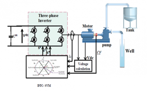
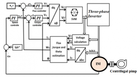
Figure 1 depicts the fundamental design of the control system [15]. It comprises of a VSI-powered induction motor in accordance with the suggested SVM-DTC approach and a centrifugal pump as the load. Table 1 lists the parameters of the employed induction motor.
Figure 1. The architecture of the system
Table 1. Induction motor used parameters
|
Element |
Rating |
|
Rs Rr Ls Lr M J Fr P |
6.75 $\Omega$ 6.21 $\Omega$ 0.5192 H 0.5192 H 0.4957 H 0.0140 0.002 2 |
2.1 Mathematical model of the Inverter water pumping system’s
The static converter's primary role is to convert continuous energy into single-phase or three-phase alternating energy. The DC/AC converter is positioned between the source of continuous power and the motor pump. In this paper, the ideal scenario of a three-phase inverter with two voltage levels, represented by flawless instant-switching switches, is considered. Considered a perfect voltage source, the inverter has low internal impedance.
The voltages of the output phases are represented by the following equations [16, 17]:
$\left[\begin{array}{l}V_a \\ V_b \\ V_c\end{array}\right]=\frac{V_p}{3}\left[\begin{array}{ccc}2 & -1 & -1 \\ -1 & 2 & -1 \\ -1 & -1 & 2\end{array}\right]\left[\begin{array}{l}S_1 \\ S_2 \\ S_3\end{array}\right]$ (1)
The control signals applied to the switches are $\left(S_1, S_2, S_3\right)$. Filtering or PWM systems (Pulse Width Modeling) that modulate the duration of the pulses to produce a sine wave output may be used to improve the inverters.
2.2 Mathematical model of the induction motor
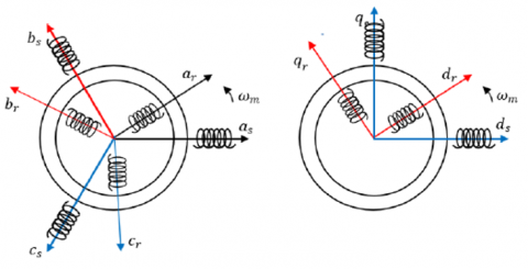
The model of the machine in the three-phase system is quite complicated; thus, we request its simplification as part of the Park's transformation [18]. Physically, it may be described by changing three windings of the machine into two, as seen in Figure 2.
The Park transformation transforms the stator windings as, bs, and cs and the rotor windings $a_r, b_r$, and $c_r$ into two stator windings $d_s$ and $q_s$ and two rotor windings $d_r$ and $q_r$, respectively. "d" indicates the direct axis, whereas "q" indicates the quadrature axis.
$\left[P\left(\theta_s\right)\right]=C \cdot\left[\begin{array}{ccc}\cos \theta_s & \cos \left(\theta_s\right) & \cos \left(\theta_s\right) \\ \sin \theta_s & \sin \left(\theta_s\right) & \sin \left(\theta_s\right) \\ 1 / \sqrt{2} & 1 / \sqrt{2} & 1 / \sqrt{2}\end{array}\right]$ (2)
Figure 2. Schematic representation of the Park transform
In designing the direct torque control, the state representation in the stator-linked frame is used. The notation for this reference frame is $(\alpha, \beta)$, which translates to the conditions $d \theta s / d t=0$ and $d \theta r / d t=\omega r$. Then, the following electrical equations are obtained [19]:
$\left\{\begin{array}{c}V_{\alpha s}=R_s i_{\alpha s} \frac{d \varphi_{\alpha s}}{d t} \\ V_{\beta s}=R_s i_{\alpha s} \frac{d \varphi_{\beta s}}{d t} \\ 0=R_r i_{\alpha r}+\frac{d \varphi_{\alpha r}}{d t}-\omega_r \varphi_{\beta r} \\ 0=R_r i_{\beta r}+\frac{d \varphi_{\beta r}}{d t}-\omega_r \varphi_{\alpha r}\end{array}\right.$ (3)
By substituting the expressions of the equation's currents, we can formulate the induction machine's equation of state in a coordinate system related to the stator [20]:
$\frac{d X}{d t}=A X+B U$ (4)
$X=\left[\begin{array}{c}\varphi_{\alpha s} \\ \varphi_{\beta s} \\ \varphi_{\alpha r} \\ \varphi_{\beta r}\end{array}\right] ; A=\left[\begin{array}{cccc}-\frac{R_s}{\sigma L_s} & 0 & \frac{M R_s}{\sigma L_s L_r} & 0 \\ 0 & -\frac{R_s}{\sigma L_s} & 0 & \frac{M R_s}{\sigma L_s L_r} \\ \frac{M R_r}{\sigma L_s L_r} & 0 & -\frac{R_r}{\sigma L_r} & -\omega_r \\ 0 & \frac{M R_r}{\sigma L_s L_r} & \omega_r & -\frac{R_r}{\sigma L_r}\end{array}\right]$ (5)
$B=\left[\begin{array}{ll}1 & 0 \\ 0 & 1 \\ 0 & 0 \\ 0 & 0\end{array}\right]$ and $U=\left[\begin{array}{c}V_{\alpha s} \\ V_{\beta s}\end{array}\right]$ (6)
In a frame of reference connected to the stator, electromagnetic torque is described as a function of stator fluxes and currents [21]:
$T_e=p\left(\varphi_{\alpha s} i_{s \beta}-\varphi_{\beta s} i_{\alpha s}\right)$ (7)
The underlying connection of dynamics enables the writing of:
$T_e-T_l=J(d \Omega / d t)+f \Omega$ (8)
where, $T_e$ represents the electromagnetic torque generated by the motor, $T_l$ represents the resistive torque, J represents the moment of inertia of all spinning elements, and f represents the coefficient of friction. This connection is a differential equation whose independent variable is the rotor's angular velocity.
2.3 Load equations
According to their working mechanism, water pumps may be categorized as either volumetric or centrifugal. In addition to these two classes, which will be detailed in more detail later, there are two further kinds of pumps that may be separated based on their physical placement in respect to the water being pumped: the suction pump and the delivery pump. In boreholes, centrifugal pumps are the most prevalent form of pump. A casing containing a high-speed spinning impeller is known as a stage. Centrifugal force propels the water radially out of the casing through the impeller. When extra pressure is required beyond what a single stage can provide, additional stages are added. Before a centrifugal pump can overcome the static lift necessary to push water into the storage tank, it must operate at a particular speed [22]. A centrifugal pump is a mechanical device that converts mechanical energy into fluid pressure using centrifugal force. It is very efficient and can pump vast quantities of water [23]. The centrifugal pump load torque $T_l$ may be calculated as follows [24]:
$T_l=K_p \omega_r^2$ (9)
where, $K_p$ is the constant of proportionality, which is defined as follows:
$K_p=P_{n p} / \omega_{n p}^3$ (10)
The head of the pump and the available mechanical power at the revolving impeller define the water flow and pressure of the pump. Affinity laws, which need just the pump's ratings and real input parameters, rotor speed and torque [25], may facilitate the estimate of the pump's output characteristics.
$\left\{\begin{array}{l}H^{\prime}=\left(\omega_r / \omega_{n p}\right)^2 H \\ Q^{\prime}=\left(\omega_r / \omega_{n p}\right) Q \\ P^{\prime}=\left(\omega_r / \omega_{n p}\right)^2 P\end{array}\right.$ (11)
where, H, Q, and P are the rated parameters of the pump at the rated speed, while $\omega_{n p}, H^{\prime}, Q^{\prime}$, and $P^{\prime}$ are the rated parameters of the pump at the different speed $\omega_r$. The following table (Table 2) represents the pump's output characteristics used in our research.
Table 2. Centrifugal pump used parameters
|
Element |
Rating |
|
The nominal speed The nominal flow rates The nominal head pump The nominal power hydraulic |
100 rad /s 10 m3/h 19.1 m 520 W |
3.1 Conventional direct torque control
3.1.1 DTC principle
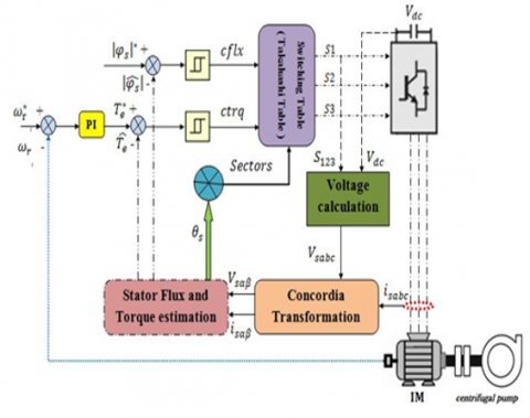
By using hysteresis controllers, DTC regulates the stator flux and electromagnetic torque. The 2L-VSI switching states may be chosen from a control table using the output of these controllers. For DTC, it is assumed that the rotor speed is high in order to ignore the voltage drop induced by stator resistance in the stator voltage calculation. This approximation demonstrates that the voltage vector delivered to the inverter may alter stator flow. It achieves decoupled control of the stator flux and electromagnetic torque in the stationary frame $(\alpha, \beta)$ and allows induction machines to respond to electromagnetic torque with precision and speed. It utilizes a switching table to pick the proper voltage vector. The switching states are closely related to the machine's stator flux and torque fluctuation. Therefore, the selection is accomplished by limiting the magnitudes of the flux and torque to two hysteresis bands. These controllers provide independent regulation of these two quantities. The flux and torque errors as well as the outputs of hysteresis controllers determine the proper voltage vector for each commutation period [12]. The main scheme of DTC is presented in Figure 3.
Figure 3. Block diagram of DTC of induction motor feeding a centrifugal pump
3.1.2 Torque and flux estimation
It is important to note that all calculations for determining the stator flux s and electromagnetic torque $T_e$ are performed in the reference $(\alpha, \beta)$. The flux components are denoted as $(\alpha, \beta)$ components of stator current and stator voltage vs the following [26]:
$\hat{\varphi}_{\alpha s}=\int_0^t\left(v_{\alpha s}-R_s i_{\alpha s}\right) d t$ (12)
$\hat{\varphi}_{\beta s}=\int_0^t\left(v_{\beta s}-R_s i_{\beta s}\right) d t$ (13)
The estimation of the electromagnetic torque and stator flux is provided by the following expressions [27]:
$\hat{\varphi}_s=\sqrt{\hat{\varphi}_{\alpha s}^2+\hat{\varphi}_{\beta s}^2}$ (14)
$\theta_s=\tan ^{-1}\left(\frac{\hat{\varphi}_{\beta s}}{\hat{\varphi}_{\alpha s}}\right)$ (15)
$T_e=p\left(\varphi_{\alpha s} i_{s \beta}-\varphi_{\beta s} i_{\alpha s}\right)$ (16)
The components of the voltage vector ($\mathrm{V \alpha s}$ and $\mathrm{V} \beta \mathrm{s}$) are calculated based on the switching states (Sa, Sb, Sc) provided by the switching table, so:
$\left\{\begin{array}{c}\overline{\mathrm{V}}_{\alpha \mathrm{s}}=\frac{1}{3} \mathrm{~V}_{\mathrm{dc}}\left(S_1-S_2-S_3\right) \\ \overline{\mathrm{V}}_{\beta \mathrm{s}}=\sqrt{\frac{1}{3}} \mathrm{~V}_{\mathrm{dc}}\left(S_2-S_3\right)\end{array}\right.$ (17)
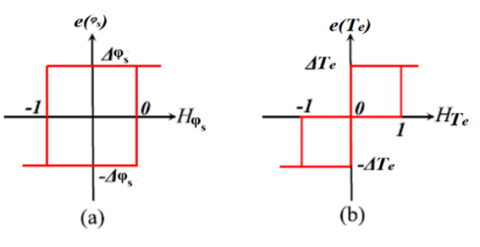
3.1.3 Hysteresis controllers
As shown in Figure 4a, a two-level hysteresis controller maintains the stator flux in a circular crown. Moreover, a three-level hysteresis controller regulates the electromagnetic torque of the motor in both rotational directions, providing either positive or negative torque. Figure 4b depicts a hysteresis torque controller with three levels [28].
Figure 4. Hysteresis controllers for a stator flux and b electromagnetic torque
3.1.4 Switching table
A three-level hysteresis comparator receives the difference between the estimated torque and the reference torque. In contrast, the difference between the calculated stator flux and the reference stator flux is sent into a two-level hysteresis regulator. Using the output states of the two hysteresis comparators and the stator flux location, the voltage vectors of the inverter may be chosen from a switching table (Table 3) [10].
Table 3. Switching table (TAKAHASHI table)
|
Sector |
|||||||
|
Flux |
Torque |
1 |
2 |
3 |
4 |
5 |
6 |
|
Increase |
Increase |
V2 |
V3 |
V4 |
V5 |
V6 |
V1 |
|
No change |
V0 |
V7 |
V0 |
V7 |
V0 |
V7 |
|
|
Decrease |
V6 |
V1 |
V2 |
V3 |
V4 |
V5 |
|
|
Decrease |
Increase |
V3 |
V4 |
V5 |
V6 |
V1 |
V2 |
|
No change |
V7 |
V0 |
V7 |
V0 |
V7 |
V0 |
|
|
Decrease |
V5 |
V6 |
V1 |
V2 |
V3 |
V4 |
|
3.1.5 Direct torque control-space vector modulation (DTC-SVM)
As mentioned previously, the conventional DTC algorithm uses the hysteresis comparators for the torque and flux as well as the sector position of the instantaneous flux to produce the correct switching states for the inverter. The primary shortcomings of the hysteresis comparator are its high torque and flux ripples, as well as its variable switching frequency. Diverse researchers agree to combine the benefits of Direct Torque Control and Field Oriented Control within the same framework to overcome these drawbacks, resulting in the DTC-SVM method. In contrast to the DTC, which uses instantaneous measurements and direct computations to determine the inverter's switching state, the DTC-SVM uses average values and the SVM algorithm to determine the inverter's switching state. As seen in Figure 5, the DTC-SVM estimates the reference voltage vector and modifies it using the SVM approach to generate inverter switches. In this design, the torque and flux of the induction motor are controlled. The method of control is performed by regulating the voltages generated by PI controllers. To generate switching pulses for the inverter, the SVM block is utilized. The proposed DTC-SVM system uses three PI controllers to handle speed, flux, and torque errors. The speed error, which is handled by the PI speed controller, determines the torque reference $\left(T_e^*\right)$. The PI flux controller and PI torque controller are responsible for making the command voltages $V_{d s}$ and $V_{q s}$, respectively [29].
Figure 5. DTC-SVM configuration
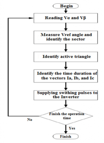
Figure 6. Flow-chart of DTC-SVM algorithm
Figure 6 depicts the DTC- SVM's flow chart. As shown in Figure, the main steps start from reading $V_\alpha$ and $V_\beta$ after calculated the voltage required driving the error in the torque and flux to zero, the following identify the sector, where exist the vector active such represents Figure 7 to generate the switching pulses. If the inverter can't provide the required voltage, the voltage vector that drives the torque and flux toward the demand value is chosen and kept for the rest of the cycle.
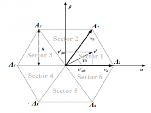
Figure 7. Space vector of a two-level inverter
In the instance of the two-level inverter, space vector switching attempts to match the sinusoidal reference voltage to the six active space vectors and two zero-voltage vectors generated by the inverter, as seen in Figure 8. To realize the reference voltage vector Vs to its neighboring vectors with the lowest possible switching frequency, the complete cycle Ts must be split into three parts Ta, Tb, and T0. Using the straightforward geometry of Figure 7 produces the following on-time or volt-second calculations [30, 31]:
$\bar{V}_s T_s=T_a \bar{V}_a+T_b \bar{V}_b$ (18)
where, va=(1, 0) and vb=(0.5, h).
$T_a+T_b+T_0=T_s$ (19)
Take the components of Vs along the quadrature axis to yield:
$v_{\alpha 0}^s T_s=t_a+0.5 t_b$ (20)
$v_{\beta 0}^s T_s=h t_b$ (21)
The on-time periods may be derived from the preceding equations as follows:
$T_a=T_s\left[v_{\alpha s}^s-\frac{v_{\beta 0}^s}{2 h}\right]$ (22)
$T_b=T_s\left[\frac{v_{\beta 0}^s}{h}\right]$ (23)
Rest of the time will consist of:
$T_0=T_s-T_a-T_b$ (24)
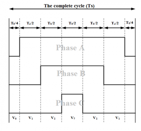
Figure 8 depicts the leg voltages resulting from the generation of reference vectors in sector 1. Each nonzero vector's temporal length is split into two equal pieces. The length of the zero vectors is uniformly divided from V0 to V7; hence, the switching sequence of the space vector during period modulation is V0, V1, V2, V7, V7, V2, V1, and V0. [33].
$\left|\bar{v}_s^*\right|=\frac{2}{3} V_{d c} \cos \left(\frac{\pi}{6}\right)=\frac{1}{\sqrt{3}} V_{d c}$ (25)
Figure 8. Leg voltages in sector 1
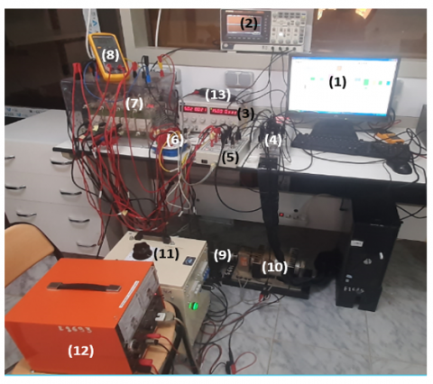
4.1 Experimental system setup
(1) A personal computer equipped with Controldesk control software.
(2) Numerical Oscilloscope.
(3) Power supply 5 V and 15 V.
(4) dSpace 1104 acquisition card.
(5) Current sensors.
6) Amplification board.
(7) Semikron power converter consisting of a rectifier, an IGBT inverter and adaptation interfaces (5V - 15V); with nominal characteristics: 1000 V, 30 A.
(8) Digital Multimeter.
(9) 1.1kW squirrel cage motor.
(10) Magnetic powder brake and its control unit (12).
(11) Three phases autotransformer (0-450 V).
(13) Voltage sensor.
In order to evaluate the efficacy of the suggested strategies, experimental activities were conducted utilizing Figure 9 as a benchmark. For the purpose of validating the performance and efficacy of the proposed control approaches, a test bench for applying the techniques to a water-pumping system has been designed. The experimental testing station is shown in Fig. It consists of a dSpace 1104 card, computer-connected control desk software, a three-phase power supply (50 Hz), an incremental encoder, a power electronics Semikron module (consisting of a rectifier and an IGBT inverter), a powder brake, and a 1.1 kW induction motor. However, it should be mentioned that the control loop used current sensors. The present sensorless vector control was developed on a DS1104 board where measurements, control variables, and ControlDesk software may be coupled. The encoder signal of the motor is picked up by one of the board's incremental encoder interfaces, while one Analogue/Digital Converter (ADC) is needed to evaluate the DC-voltage recorded by the dc-link voltage sensor. On the basis of the measured values, the controller board executes the control algorithm and determines the corresponding inverter control signals, which are generated on the DSP subsystem of the board via the Digital Input/Output (Digital I/O) board, to specify the converter's output voltage and frequency. Note that the load torque (pump torque) was utilized in the control loop through the dSpace 1104 board to set/extend the value of the powder brake. The complete parameters associated with the induction motor and water-pump are given in Appendix.
Figure 9. Configuration diagram of experimental setup
4.2 Comparison and discussion experimental results
(a) By DTC
(b) By DTC-SVM
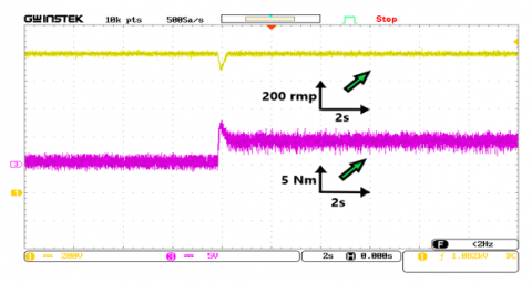
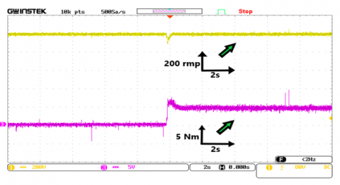
Figure 10. Torque-Speed by DTC, and by DTC-SVM
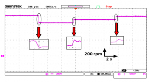
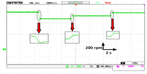
The corresponding real-time results are shown below. Figures 10a and 10b depict the based speed control of the induction motor (the reference speed is set to 1000 rpm) and the electromagnetic torque when a load torque (pump torque) of 5 N.m is applied using the traditional DTC and DTC-SVM approaches, respectively. By using DTC-SVM, the electromagnetic torque exhibits fewer ripples than traditional control. Even at the rated load, the reaction of the control system to the speed reversal test is seen to be quite excellent.
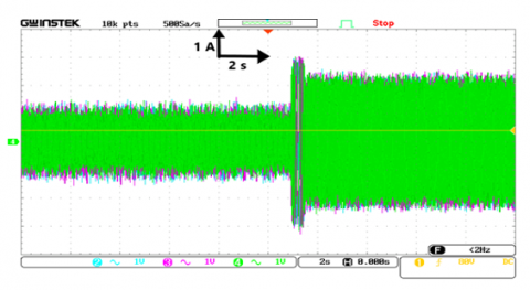
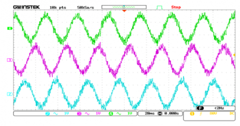
Figure 11. Three phase currents by DTC
Figure 12. Three-phase currents without load by DTC
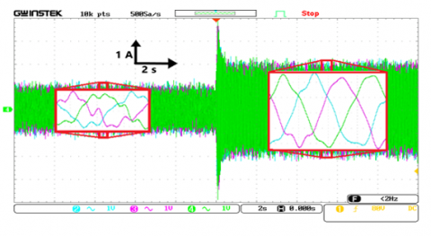
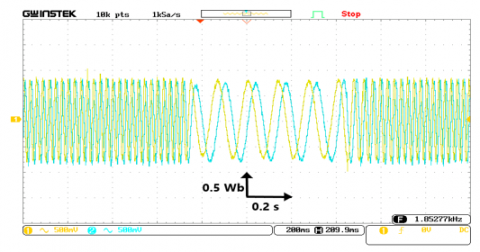
Figure 13. Alpha-beta currents by DTC
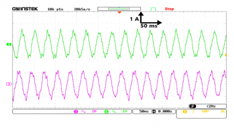
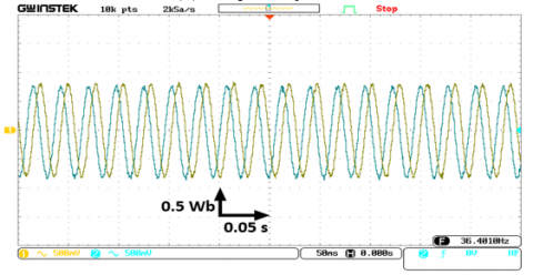
Figure 14. Three-phase currents without-under pump load by DTC-SVM
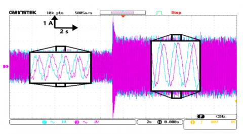
Figure 15. Alpha-beta currents by DTC-SVM
Currents without-under pump load by DTC, Three-phase Currents without load by DTC, Alpha-beta currents estimated by DTC, Three-phase currents without-under pump load by DTC-SVM, and Alpha-beta Currents without-under pump load by DTC-SVM are shown in Figures 11, 12, 13, 14, and 15, respectively. The rotor and stator current components for both approaches are the same. They are responsive to the torque fluctuations generated by the load. Their form is sinusoidal. As with traditional DTC, the steady state current response of the DTC SVM exhibits little ripple in stator current and a nearly sinusoidal wave shape. The ripple of the stator current is quite strong, displaying the phase current and its harmonic spectrum. Because of hysteresis controllers, the quality of DTC-SVM stator current waveforms is clearly better than that of traditional DTC.
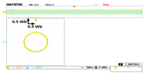
(a) Trajectory flux
(b) Alpha-beta flux
Figure 16. The stator flux by DTC
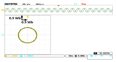
(a) Trajectory flux
(b) Alpha-beta flux
Figure 17. The stator flux by DTC-SVM
Figures 16a, 16b, 17a, and 17b show, respectively, the stator flux trajectory as measured by DTC, the Alpha-beta Flux under-without pump as measured by DTC, the stator flux trajectory as measured by DTC-SVM, and the Alpha-beta Flux under pump as measured by DTC-SVM. The steady-state behavior of both the traditional techniques and the new ways is shown by these data. 0.8 Wb is the instruction for the stator's flux. On the basis of these findings, it is possible to see that the approach that is presented, which is based on the SVM methodology, gives fewer flux ripples.
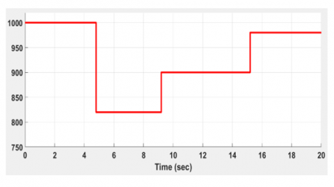
Figure 18. Speed reference imposed
(a) By DTC
(b) By DTC-SVM
Figure 19. Rotor-speed measured
Figures 18, 19a, and 19b respectively represent the motor reference speed, the measured rotational speed, as determined by DTC and DTC-SVM approaches, and the motor reference speed. Even when operating at the rated load, the control system had a very excellent reaction in terms of how it dealt with the speed variation test. This is something that can be seen. However, it is important to keep in mind that traditional DTC is inferior to DTC-SVM when measuring dynamic's performance at low speeds. It is also possible to note that the pumping system has exceptional tracking performance with a nominal pump speed of equal to 1000 revolutions per minute.
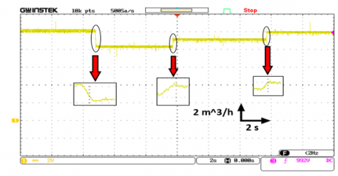
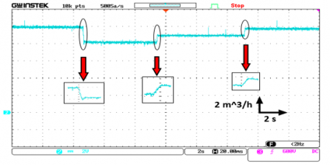
The flow rate that was measured in the pump by DTC and DTC-SVM may be seen in Figures 20a and 20b, respectively. The pump has been imposed with a flow rate that is nominally 10 $m^3 / \mathrm{h}$. as shown by the fact that the tracking performance remains stable despite significant rotor speed variations.
(a) By DTC
(b) By DTC-SVM
Figure 20. Flow rate measured
(a) By DTC
(b) By DTC-SVM
Figure 21. Head pump
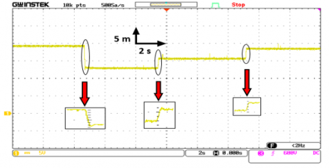
Our pumping system has been enforced with a nominal head pump of 19.1 meters. Figures 21a and 21b, respectively, demonstrate the behavior of the head pump in response to variations in the speed of the rotor when DTC and DTC-SVM were used to analyze the data. This was the fast track of the system, and it forced the rotor to move at a very high speed.
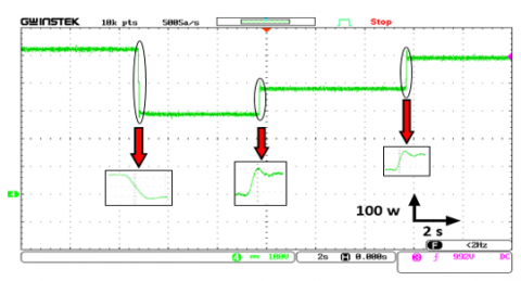
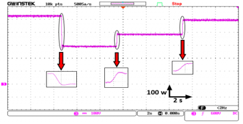
The hydraulic power also influenced the fast at any rotor speed, which is depicted in Figures 22a and 22b by DTC and DTC-SVM, respectively. Everyone knows that 520 W is the standard for hydraulic power in our water system, such we described in Table 2.
It is possible to see that any improvement in IM behaviors is a direct increase in the performance of the head pump, flow rate, and hydraulic power (the water-pumping system globally).
(a) By DTC
(b) By DTC-SVM
Figure 22. Hydraulic power
We are able to present this prototype with a change in speed as a pumping system that is based on renewable energies such as solar energy, so that the change in speed represents the continuous change in energy that is given by the solar panels. In other words, we are able to demonstrate that the change in speed represents the continuous change in energy that is given by the solar panels. Altering the voltage at which the system is supplied with power is one way to accomplish this goal. For example, if there is a change in the radiation, there will be a corresponding shift in the voltage that is given to the motor that feeds the pump. This will occur because of the change. In today's world, these technologies are being put to use in the fields of agriculture and irrigation in parts of the world that are geographically isolated. The system that was looked at shows how the yield of the central pump and its features affect how the engine works, as well as how the control mechanism helps the system work as well as it can in its current state.
In this paper, a study using a prototype of a direct torque control method that is based on space vector modulation has been provided for an induction motor that is driven by a two-level inverter. The performance of traditional DTC should be improved, and each improvement in IM behaviors should result in an increase directly in the performance of the head pump, flow rate, and hydraulic power (the water-pumping system globally). The purpose of this study was to address the experimental validation of DTC-SVM control for a pumping system by using the dSPACE DS1104 platform. It has been shown that both the dynamic model of IM as well as the fundamental concept of DTC methods have developed in detail the control approach known as DTC, which is based on space vector modulation. Here is a list of the most important things that were found when a prototype of the pumping system was used to test the system controls:
• Using space vector modulation, also known as SVM, is an effective way to improve DTC. Flux and torque ripples are reduced. As a result, there are fewer issues that might arise with IM, such as aging, mechanical vibrations, heating, etc. The pump will have problems as a result.
• Compared to traditional DTC, the suggested method reduces the amount of harmonic distortion in the rotor and stator currents by 51%, resulting in optimal optimization.
• The benefits of traditional DTC, such as its quick response, torque dynamics, and ruggedness, are kept.
Finally, we commend that this improved pump performance technology is suitable for the use of the pump powered by synchronous engines, and will be part of our future work and other engines if possible.
|
IM |
induction motor |
|
$\mathrm{V}_{\mathrm{ds}}$ |
The stator voltage in d coordinate system |
|
$\mathrm{V}_{\mathrm{qs}}$ |
The stator voltage in q coordinate system |
|
$\mathrm{V}_{\mathrm{s} \alpha}$ |
The stator voltage in the stationary frame $\alpha$ |
|
$\mathrm{V}_{\mathrm{s} \beta}$ |
The stator voltage in the stationary frame $\beta$ |
|
$\mathrm{R}_{\mathrm{s}}$ |
stator resistance of IM |
|
$\mathrm{R}_{\mathrm{r}}$ |
rotor resistance of IM |
|
Greek symbols |
|
|
$\omega_{\mathrm{m}}$ |
the rotor electrical frequency in rad/s |
|
$\varphi^*$ |
flux reference |
[1] Gupta, D.K., Kulkarni, R.D., Srivastava, G.D. (2022). Comparative analysis of DTC and FOC techniques on PHT Pump-motor simulating coast-down speed-time characteristic for nuclear power plant. In 2022 3rd International Conference for Emerging Technology (INCET), 1-7. 10.1109/INCET54531.2022.9824914
[2] Saoudi, A., Krim, S., Mimouni, M.F. (2021). Enhanced intelligent closed loop direct torque and flux control of induction motor for standalone photovoltaic water pumping system. Energies, 14(24): 8245. https://doi.org/10.3390/en14248245
[3] Massaq, Z., Abounada, A., Benkirane, O., Ramzi, M. (2021). Modern control of a standalone solar pumping system based on asynchronous motor. In 2021 9th International Renewable and Sustainable Energy Conference (IRSEC), 1-6. https://doi.org/10.1109/IRSEC53969.2021.9741126
[4] Mehazzem, F., Reama, A., Charles, P., Soubdhan, T. (2021). Integral backstepping improvement versus classical and multiscalar backstepping controllers for water IM‐pump fed by backstepping MPPT PV source based on solar measurements in a tropical insular region. IET Renewable Power Generation, 15(12): 2629-2644. https://doi.org/10.1049/rpg2.12217
[5] Rai, R., Shukla, S., Singh, B. (2020). Sensorless field oriented SMCC based integral sliding mode for solar PV based induction motor drive for water pumping. IEEE Transactions on Industry Applications, 56(5), 5056-5064. https://doi.org/10.1109/TIA.2020.2997901
[6] Abd El Sattar, M., Ahmed, K., AboZied, A., Diab, A.A. Z. (2021). Adaptive MPPT of water photovoltaic pumping system based on vector controlled induction motor drives. Journal of Advanced Engineering Trends, 41(2): 261-274. https://doi.org/10.21608/JAET.2021.47871.1065
[7] Rekioua, D., Mohammedi, A. (2020). Direct torque control for autonomous photovoltaic system with MPPT control. Turkish Journal of Electromechanics and Energy, 5(2): 48-55. https://sloi.org/urn:sl:tjoee52159
[8] Errouha, M., Motahhir, S., Combe, Q. (2022). Twelve sectors DTC struategy of IM for PV water pumping system. Materials Today: Proceedings, 51: 2081-2090. https://doi.org/10.1016/j.matpr.2021.12.214
[9] Vanaja, D.S., Stonier, A.A., Mani, G., Murugesan, S. (2022). Investigation and validation of solar photovoltaic-fed modular multilevel inverter for marine water-pumping applications. Electrical Engineering, 104(3): 1163-1178. https://doi.org/10.1007/s00202-021-01370-x
[10] Sahu, A., Mohanty, K.B., Mishra, R.N. (2021). Design of MPC-PSO based torque regulator for DTC-SVM induction motor drive. In 2021 1st International Conference on Power Electronics and Energy (ICPEE), 1-6. https://doi.org/10.1109/ICPEE50452.2021.9358559
[11] Massoum, S., Meroufel, A., Massoum, A., Patrice, W. (2021). DTC based on SVM for induction motor sensorless drive with fuzzy sliding mode speed controller. International Journal of Electrical & Computer Engineering (2088-8708), 11(1): 171-181. https://doi.org/10.11591/ijece.v11i1.pp171-181
[12] El Mahfoud, M., Bossoufi, B., El Ouanjli, N., Said, M., Taoussi, M. (2021). Improved direct torque control of doubly fed induction motor using space vector modulation. International Journal of Intelligent Engineering and Systems, 14(3): 177-188. http://www.inass.org/2021/2021063016.pdf, accessed on Sept. 28, 2022.
[13] Yussif, N., Sabry, O.H., Abdel-Khalik, A.S., Ahmed, S., Mohamed, A.M. (2020). Enhanced quadratic V/f-based induction motor control of solar water pumping system. Energies, 14(1): 104-104. https://doi.org/10.3390/en14010104
[14] Alkarrami, F., Iqbal, T., Pope, K., Rideout, G. (2020). Dynamic modelling of submersible pump based solar water-pumping system with three-phase induction motor using MATLAB. Journal of Power and Energy Engineering, 8(2): 20-20. https://doi.org/10.4236/jpee.2020.82002
[15] Rkik, I., El Khayat, M., Ed-Dahhak, A., Guerbaoui, M., Lachhab, A. (2022). An enhanced control strategy based imaginary swapping instant for induction motor drives. International Journal of Electrical and Computer Engineering, 12(2): 1102-1102. https://doi.org/10.11591/ijece.v12i2.pp1102-1112
[16] Chouiekh, M., Karmouni, H., Lilane, A., Benkirane, K., Saifaoui, D., Abid, M. (2022). Control of a photovoltaic pumping system using the ABC Algorithm in EL Jadida Climate. Technology and Economics of Smart Grids and Sustainable Energy, 7(1): 1-16. https://doi.org/10.1007/s40866-022-00141-2
[17] Madark, M., Ba-Razzouk, A., Abdelmounim, E., El Malah, M. (2021). Adaptive backstepping control of induction motor powered by photovoltaic generator. International Journal of Electrical and Computer Engineering, 11(4): 2842-2842. https://doi.org/10.11591/ijece.v11i4.pp2842-2855
[18] El Haissouf, M., El Haroussi, M., Ba-Razzouk, A. (2022). DSP in the loop implementation of an enhanced direct torque control for induction motor drive. In 2022 2nd International Conference on Innovative Research in Applied Science, Engineering and Technology (IRASET), 1-6. https://doi.org/10.1109/IRASET52964.2022.9738073
[19] Mahfoud, S., Derouich, A., El Ouanjli, N.A.J.I.B., El Mahfoud, M.O.H.A.M.M.E.D. (2022). Enhancement of the Direct Torque Control by using Artificial Neuron Network for a Doubly Fed Induction Motor. Intelligent Systems with Applications, 13: 200060-200060. https://doi.org/10.1016/j.iswa.2022.200060
[20] Mohammed, N., Abdelkrim, B., Tadjeddine Ali, D., Sofiane, B.M. (2022). Optimization of proportional integral controller’s gain for speed control in direct torque control strategy using genetic algorithm. Turkish Journal of Computer and Mathematics Education (TURCOMAT), 13(2): 970-977.
[21] El Ouanjli, N., Mahfoud, S., Derouich, A., El Daoudi, S., El Mahfoud, M. (2022). Speed Sensorless Fuzzy Direct Torque Control of Induction Motor Based MRAS Method. In International Conference on Digital Technologies and Applications, pp. 779-790. https://doi.org/10.1007/978-3-031-02447-4_80
[22] Dellad, A., Kebabi, T., Dekane, A., Huseyno, S.A. (2022). Control for a solar photovoltaic water pumping system. Journal of Engineering Research and Applied Science, 11(1): 2015-2018. http://journaleras.com/index.php/jeras/article/view/280.
[23] Medhane, R., Dhamal, S., Thakre, M. (2021). Efficient solar PV array system using modified algorithm for water pumping system. In 2021 International Conference on Artificial Intelligence and Smart Systems (ICAIS), pp. 1663-1669. https://doi.org/10.1109/ICAIS50930.2021.9395773
[24] Ammar, A., Hamraoui, K., Belguellaoui, M., Kheldoun, A. (2022). Performance enhancement of photovoltaic water pumping system based on BLDC Motor under partial shading condition. Engineering Proceedings, 14(1): 22-22. https://doi.org/10.3390/engproc2022014022
[25] Gevorkov, L., Domínguez-García, J.L., Rassõlkin, A., Vaimann, T. (2022). Comparative simulation study of pump system efficiency driven by induction and synchronous reluctance motors. Energies, 15(11): 4068-4068. https://doi.org/10.3390/en15114068
[26] Errouha, M., Combe, Q., Motahhir, S., Askar, S.S., Abouhawwash, M. (2022). Design and processor in the loop implementation of an improved control for IM driven solar PV fed water pumping system. Scientific Reports, 12(1): 1-16. https://doi.org/10.1038/s41598-022-08252-7
[27] Errouha, M., Derouich, A., El Ouanjli, N., Motahhir, S. (2020). High-performance standalone photovoltaic water pumping system using induction motor. International Journal of Photoenergy, 3872529-3872529. https://doi.org/10.1155/2020/3872529
[28] Esparza Sola, T., Chiu, H.J., Liu, Y.C., Rahman, A.N. (2022). Extending DC bus utilization for induction motors with stator flux oriented direct torque control. Energies, 15(1): 374-374. https://doi.org/10.3390/en15010374
[29] Potturi, S., Mandi, R.P. (2020). Latest advances in DTC control of induction motors. International Journal of Recent Technology and Engineering (IJRTE), 8(6S): 120-123. https://doi.org/10.35940/ijrte.F1008.0386S20
[30] Chandra Sekhar, O., Lakhimsetty, S. (2020). Direct torque control scheme for a five-level multipoint clamped inverter fed induction motor drive using fractional-order PI controller. International Transactions on Electrical Energy Systems, 30(9): e12474-e12474. https://doi.org/10.1002/2050-7038.12474
[31] Mohammed, A.J., Hassan, R.F. (2021). Comparison of conventional and modified direct torque control of three-phase induction motor using three-level flying capacitor inverter. International Journal of Electrical and Electronic Engineering & Telecommunications, 10(6): 431-438. https://doi.org/10.18178/ijeetc.10.6.431-438