Wajdi Elhamzi![]()
© 2024 The author. This article is published by IIETA and is licensed under the CC BY 4.0 license (http://creativecommons.org/licenses/by/4.0/).
OPEN ACCESS
In telemedicine, the safeguarding of medical images is important, necessitating systems that uphold patient privacy, ensure image integrity, and verify authenticity. Addressing the challenge of processing time disparities in existing algorithms, this study introduces a novel field-programmable gate array (FPGA)-based crypto-watermarking system for medical image applications. The system integrates a least significant bit (LSB) watermarking technique with the Lightweight Encryption Device (LED) cryptography algorithm. The LSB technique, known for its minimal impact on image quality, is utilized to embed a concealed message, subsequently encrypted by the LED algorithm for enhanced security. Traditional software implementations of such algorithms have been hampered by significant processing delays, with times ranging up to 34 seconds for smaller images and extending to 30 minutes for larger ones. The predominant factor in these delays, the encryption/decryption process, occupies 98% of the total processing time. To address this, the LED algorithm has been accelerated using Vitis High-Level Synthesis (HLS) for hardware implementation, effectively reducing time to market. The proposed architecture, subjected to rigorous examination, testing, and evaluation, demonstrates superior performance in throughput and processing speed compared to previous works. An extensive range of digital images was employed to assess the coprocessor's efficacy. The results reveal an average Peak Signal-to-Noise Ratio (PSNR) of 86.98 dB, indicating superior imperceptibility without attacks when compared to earlier studies. Furthermore, under various attack scenarios, the system maintains high imperceptibility, with an average PSNR of 53.68 dB, surpassing previous methods in robustness. Comparative tests confirm that the proposed FPGA-based crypto watermarking outstrips Real-Time Logic (RTL) implementations, achieving a PSNR above 82 dB. This indicates a marked improvement in imperceptibility relative to prior research. Additionally, the system boasts a throughput of 449.35 Mbps and a speed enhancement of 77% over traditional software implementations, underscoring its effectiveness in the secure processing of medical images.
medical imaging, least significant bit (LSB) watermarking, LED lightweight cryptography, parallel computing, high-level synthesis (HLS), field-programmable gate array (FPGA)
In the last decade, the Internet of Things (IoT) field has grown enormously. Most domestic gadgets now have sensors, are linked to the internet, and are well integrated into our daily habits. For example, GPS tracking allows you to find a service near where you are or locate a location by showing you the last route to follow. There are also thermostats and lighting systems that can be operated remotely from an application. In short, the Internet is developing more and more of a multitude of everyday objects. Some automobiles can now warn you of danger and recommend remedies for the situation.
From a health perspective, the internet can track your movements and heart rate with smartwatches, as well as take your body temperature or blood sugar index, a significant feature for people with diabetes. IoT solutions for healthcare plans will make healthcare centers smarter and enable them to be more successful at what they do. The IoT has the opportunity to reshape the interaction and connection between users, technology, and equipment in healthcare environments, making it easier to promote better care, reduce costs, and improve outcomes. As well as linked medical devices, such as sonography, computed tomography (CT) scans, magnetic resonance imaging (MRI), and nuclear medicine imaging. These devices create massive amounts of data that interact with other IT infrastructures within the network, providing processing such as analysis and visualization.
Moreover, the hacking act of the hacker known as MedJack allowed attackers to inject malware into medical devices, which then spread through the healthcare network infrastructure.
Medical images are vulnerable to attacks like unauthorized access, tampering, or interception, posing a significant threat to patient privacy and medical diagnosis integrity, hence the need for robust security measures in eHealth networks. Attacks on secured images are defined differently than attacks on any transmitted data in general. The objective of such attacks is not only to decipher information but rather to corrupt data and distort encrypted media. These medical image attacks can be categorized into geometric attacks [1], like image scaling, rotation, and clipping; image processing attacks, like filtering and compression; and cryptographic attacks, and signal processing attacks like histogram equalization [2], contrast adjustment, gamma correction, and adaptive histogram.
Medical data stolen in these types of attacks has been used for tax evasion or identity theft practices, and it has even been used to track prescription drugs, allowing hackers to order medicines online for resale on the dark web. The medical images acquired in imaging centers and hospitals can be exchanged among several healthcare staff members to enhance patient care and medical information management. As presented in Figure 1, shared medical images are always done on insecure networks, creating several security risks and exposing medical images to threats such as data loss, manipulation, errors, and attacks. The digital version of medical images offers several benefits over their analog counterparts, including ease of storage and transmission.
To protect patient privacy, digital medical photographs must be maintained in a secure setting. It is also necessary to identify changes to the image. Watermarking in medical images achieves these goals.
Figure 1. General architecture of medical imaging communication system
The present manuscript is structured as follows: Section 2 provides contextual information about medical image safeguarding and cryptographic watermarking frameworks. Section 3 delineates the proposed approach for watermarking medical images and the algorithms used. Section 4 presents the software implementation of the proposed solution, along with the hardware acceleration technique that will be applied. Section 5 provides an elaborate exposition of the hardware design and a diverse range of experiments that employ optimization techniques. Section 6 presents the results and discussion of the hardware architecture for HLS and RTL. The conclusion is ultimately presented in Section 7.
The medical image may be disseminated through networks for various reasons, including consultation and review with a second medical expert, giving medical images to students and researchers, letting patients examine their records, and many more. Several devices, like smartphones, PCs, and tablets, among others, may all be used to access medical data that is shared through networks and servers. The primary concern is whether the information received is authentic, secure, and integrated. Following the issuance, the medical images may be inspected for examination, processed for research reasons, shared with others, and so on. The general architecture of the medical image transmission system is illustrated in Figure 1. The procedure of exchanging medical images via an unprotected connection may expose them to unexpected modifications. There is a possibility that they might be changed inadvertently besides the harmful attacks [3, 4].
The Internet of Medical Things (IoMT), which is a subset of the Internet of Things technologies, includes all the connected devices and apps used in medical and health information technology. The IoMT devices link patients, doctors, and medical devices over a secure network. Following the Deloitte [5] report for medical devices and transformation in health care, it was estimated that the IoMT market would be worth 41.2 billion and 158.1 billion, respectively, in 2017 and 2022. The IoMT’s linked medical equipment sector is predicted to grow from 14.9 billion in 2017 to 52.2 billion by 2022. Today, this estimate seems to be relatively low. Because of the COVID-19 pandemic, IoMT has grown by a factor of ten. Quarantine and lockdown orders have sped up the growth of telemedicine and telehealth. In this context, Hasan et al. [6] developed a safe image security approach using an efficient, lightweight cipher algorithm for the healthcare field. The suggested lightweight cryptographic system combines two permutation techniques to secure medical images. Regarding security and processing time, the proposed approach is examined, validated, and compared to regularly used encryption methods. The suggested algorithm’s performance was evaluated using a variety of test images.
Existing encryption systems have used the Advanced Encryption Standard (AES), Data Encryption Standard (DES), and Rivest-Shamir-Adleman (RSA) [7-9] algorithms to deal with low-level efficiency matters while considering small data sizes and high redundancy [10, 11]. As a result, these methods are challenging to manage and assure adequate security for healthcare images in the IoMT paradigm [12, 13].
Watermarking is the process of modifying data to incorporate information about it. According to the definition, it has two main aspects. The first step lets you insert a message or brand into the image without anyone noticing. In the second step, based on the watermark key, watermark algorithms can detect and/or extract the previously inserted mark. Watermarking methods are essentially divided into three categories [14]. The first approach is called “watermarking by region,” which uses the presence of zones of zero or minimal interactions in the image to provide relevant diagnostic information in Regions of Interest (ROI). They usually put the mark on the image’s black background. Second, the reversible or lossless method involves removing the watermark from the image while keeping the gray levels of the original image. These strategies also enable the updating of brand data. One drawback is that the recovered image is no longer safe when we remove the watermark. Finally, in this situation, the watermark is very subtle and can’t be erased, with a focus on how hard it is to see.
According to the available literature, recent research has shown the feasibility of implementing digital watermarking architectures using FPGA boards. The hardware and real-time implementation of digital watermarking systems are exciting topics. In recent years, several new works have been proposed and developed. The researchers focused on the different parts of the hardware design, such as how it had to work in real-time and use less power while still being able to do a lot of work. Zhang et al. [12] developed a fast image encryption system based on the CBC mode of the AES algorithm. This paper looks at AES-based image encryption to show that it is not suitable for image encryption. But digital images can be encrypted with the help of the AES used in CBC mode. The chaotic system generates the initial vector, and the look-up table approach creates AES in the tested method. Images can be encrypted using the same AES key. The sampled image cryptosystem is secure since AES is extremely secure. Moreover, simulation results suggest that the AES-based crypto-image approaches outperform those based on chaotic systems. Thus, the tested method can be utilized as a benchmark for emerging images. Image cryptosystems must be improved to keep up with base-based schemes on the same computer.
Khashan and AlShaikh [15] proposed a chaotic map for building a vast key space that can be used to identify various blocks. The critical image blocks are encrypted using a one-time pad technique. Several tests were run on different images to show the proposed architecture’s reliability and usefulness. Based on the results of the security and performance evaluations, the suggested approach may offer a high level of security with less computational complexity, making it suitable for real-time image encryption.
Das et al. [16, 17] developed a novel reversible image watermarking technique based on embedding bit rate control and contrast mapping. The suggested approach is validated using MATLAB and Xilinx tools. The results show that an FPGA Zynq-7000 board can be used to implement a low-resource, power-optimized solution that works in real-time. The suggested architecture can operate at a 100 MHz frequency and 46 Mbps throughput. In the same context, Arumugham et al. [18] have designed an integrated chaos-watermarking encryption system. Based on chaotic algorithms, IWT and SVD were used to add a watermark with a patient’s name to a DICOM image that had been encrypted. The Altera Startix FPGA platform implements a medical image encryption system. A trade-off between power consumption and security level perpetually exists. The proposed algorithm also beats the FPP, a problem with other methods for watermarking medical images.
Similarly, Hazra et al. [19] implemented a reversible watermarking algorithm using FPGA circuits. This technique is dedicated to medical image applications. The Xilinx System Generator tool ensures the proposed design will work in hardware. The results obtained are very encouraging and show very high performance. The maximum frequencies are around 445 and 201 MHz, and the power consumption is about 1.215 and 0.104 W for embedding and extraction blocks, respectively. Also, the hardware could be built into medical diagnostic tools like CT and MRI scanners and X-ray machines to make the images more secure.
Maity et al. [20] showed how to control the quality of grayscale images by hiding data in a way that can be undone. A user-defined secret key makes a watermark that depends on the content, which controls access to the scheme’s quality. The system exhibits high PSNR and MSSIM values, increased embedding capacity, and resilience to different signal processing processes. The hardware architecture takes up only 986 slices with a low power consumption of around 55 mW when operating at 130 MHz as its maximal frequency. In this context, Phadikar et al. [21] suggested an efficient hardware architecture for implementing a quality access control method based on the discrete cosine transform. Parallel processing makes the VLSI architecture implied, which is based on an FPGA circuit, better. Compared to similar approaches described in the literature, the technique reduces power use by 90%. It can run at a maximum speed of 131.16 MHz and process a 512×512 image at a throughput of 1.34 GB/s for both the encoder and the decoder.
Using phase congruency and singular value decomposition, Nayak et al. [22] developed an image watermarking method that can be changed to make it more effective as a multi-parameter optimal solution to hide metadata. The algorithm’s performance is evaluated in MATLAB using several criteria, such as the Normalized Cross-Correlation (NCC) index, PSNR, and structural similarity. A high-performance FPGA board was used to implement the proposed design.
Kaibou et al. [23] proposed a real-time FPGA implementation of a secure chaos-based digital crypto-watermarking system in the DWT domain using a codesign approach. The suggested crypto watermarking system’s performance has been assessed using various metrics and statistical/differential analyses in terms of watermarked image quality, robustness, and information security level. These results showed how well the methods worked and proved that the overall Hardware/Software (HW/SW) codesign method was suitable. The crypto watermarking system that was made can be used for images and videos, especially in the medical field.
To improve the crypto watermarking system, Borra and Thanki [24] suggest a non-blind, fragile DCT domain watermarking scheme based on CS-based cryptography that is proposed for invisibly hiding encrypted watermark images. The simulation results indicate that the proposed scheme has a maximum payload capacity of 1 bpp and a high imperceptibility of 92 dB.
An approach for image watermarking based on LSB and image gradients was introduced by Faheem et al. [25]. After dividing the original image into nonoverlapping blocks, the gradient was computed for each block. Ultimately, LSB was employed to incorporate watermarked bits. This method operated within the temporal domain, offering computing efficiency and superior perceptual quality. It demonstrated substantial resilience to image processing and geometrical attacks.
The present research [26] investigates the incorporation of the LSB technique with the quantum Haar wavelet transform. The proposed approach utilizes a quantum wavelet transform to include a binary image in the LSB of the quantum image. The quantum Haar wavelet process guarantees that the watermark is evenly distributed throughout the entire image, enhancing its resistance against attacks. To sum up, using both LSB and the quantum Haar wavelet transform together in watermarking for quantum images is a safe and reliable way to keep private quantum information safe.
It is well known that encryption and watermarking may be blended. Two categories may be made based on how they are combined. The first type is watermarking, followed by the encryption process (WFE). This method puts the watermark into the host image before the watermarked data is encrypted. On the receiving end, the encrypted data with the watermark is first decrypted, and then the data with the watermark is retrieved. The second type is encryption followed by the watermarking process (EFW), which involves inserting the encrypted watermark into the original encrypted data. It has the advantage of homomorphic encryption. The most frequent approach to watermark embedding is to include the watermark in the cover object’s LSB pixel. Despite its simplicity, LSB substitution has several downsides. Because that can survive changes like cropping, adding unwanted noise, or lossy compression, a more advanced attack that sets the LSB bits of each pixel to one will completely destroy the watermark without damaging the cover object. Once a hacker understands the technique, he may readily modify the encoded watermark. For this reason, the encryption process is still fundamental to strengthening security and avoiding hackers.
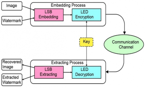
Several algorithms, like the well-known AES, DES, and RSA, have been made and suggested for encrypting images. But using these algorithms with the Internet of Medical Objects is not a good idea for hardware systems because it could go against the real-time rule and use a lot of power. So, a crypto-watermarking process that works must use the least amount of hardware resources possible. In this work, we developed a lightweight cryptography algorithm to get around problems with power use, security level, and processing time. The WFE approach is the main design of the proposed system. To protect data, it uses a lightweight cryptography algorithm called LED [27-30] after using the LSB watermarking technique to hide a secret message, as illustrated in Figure 2.
Figure 2. Architecture of the proposed crypto-watermarking system
3.1 Watermark embedding/extraction process
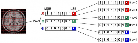
This process consists of two steps. First, using the watermark image, the LSB technique is applied to the medical image. The image comprises three components (R, G, B).
Each pixel in the image is composed of 3 unsigned 8-bit values (red, green, and blue), with a range between 0 and 255 represented by 8-bit values (b7b6b5b4b3b2b1b0). b7 is the most significant bit (MSB), and b0 is the LSB. For example, if we assume that the pixel candidate is equal to 254 (11111110), changing the MSB state from 1 to 0 becomes 126 (01111110), causing a drastic change. On the other hand, if we change the LSB from 0 to 1, we obtain 255 (11111111), like nothing’s changed. This LSB technique hides the message or image into the candidate image.
Figure 3 presents the embedding process based on the LSB watermarking scheme. The transformation process is applied to the input image.
Figure 3. The LSB embedding process
The inserted message can contain several pieces of information about the patient and his associated information, such as the folder number, the attending doctor, the date, etc. Indeed, a logo could be hidden in the original image, proving that the shared medical image is authentic.
3.2 Watermark encryption/decryption process
If the watermark is already embedded, the second step encrypts the watermarked image based on the LED algorithm 1 [22]. The LED cipher uses the fewest chips compared to other cryptosystems of similar strength. As a block cipher, the LED belongs to the S-PN category. Two variations exist, one for each possible key size. Compared to LED128, whose key length is 128 bits, LED64’s key length is just 64 bits. The LED64 has 32 rounds, while the LED128 has 48. In this analysis, the LED64 was used to encrypt and decrypt information. Remember that from now on, you should be using LED64 instead of LED. The four fundamental operations that constitute the LED algorithm are known as AddConstants, S-Box, ShiftRows, and MixColumns, as illustrated in Figure 4.
AddConstants: In this function, bitwise XOR operations are used to add more round constants to the state. The round constants of a linear feedback shift register (LFSR) are given as 6-bit values in the RC [5:0] format.
S-box: The LED algorithm employs the same S-box table as the PRESENT algorithm [31]. This table contains 16 nibbles (4-bit) of elements from 0x0 to 0xF as inputs and their corresponding hexadecimal values as outputs. The substitution box for LED is given in Table 1.
Table 1. Substitution box of LED cipher
|
X |
0 |
1 |
2 |
3 |
4 |
5 |
6 |
7 |
|
S (X) |
C |
5 |
6 |
B |
9 |
0 |
A |
D |
|
X |
8 |
9 |
A |
B |
C |
D |
E |
F |
|
S (X) |
3 |
E |
F |
8 |
4 |
7 |
1 |
2 |
ShiftRows: For i= 0; 1; 2; 3; row i of the array state is rotated i cell positions to the left.
MixColumns: Each array state column is identified as a column vector and is replaced by the vector multiplied by the matrix M given by Eq. (1).
$M D S=\left(\begin{array}{llll}0 & 1 & 0 & 0 \\ 0 & 0 & 1 & 0 \\ 0 & 0 & 0 & 1 \\ 4 & 1 & 2 & 2\end{array}\right)^4=\left(\begin{array}{llll}4 & 1 & 2 & 2 \\ 8 & 6 & 5 & 6 \\ B & E & A & 9 \\ 2 & 2 & F & B\end{array}\right)$ (1)
Here is a description of LED encryption algorithm 1, as the crypto module uses it in the form of pseudo-code.
The plaintext and the constant matrix will be XOR’d together as part of the work that the AddConstants function is expected to do. An 8-byte representation of the key size was used to generate the matrix, beginning with Ks7 and ending with Ks0.
To generate the first column of the matrix, an XOR operation was performed on the key bytes while they were in their respective places. The second column’s six-round constant bits (RC5 to RC0) started with zero and underwent a one-bit left shift for each round, with RC0 being the outcome of a Xor between RC5, RC4, and one. The last bit, RC0, resulted from an XOR between RC5 and RC4. To begin, we will provide the constant matrix, which is represented in Figure 4.
|
Algorithm 1. LED Encryption procedure with 64-bit and r = 32. |
|||||
|
1 |
Require: A 64-bit plaintext P, 64-bit key K. |
||||
|
2 |
Output: A 64-bit ciphertext C. |
||||
|
3 |
S ← P |
||||
|
4 |
SK ← GenerateSubkey (K) |
||||
|
5 |
S ← AddRoundKey (S, SK) |
||||
|
6 |
For j = 1 to (r/4) do |
||||
|
7 |
|
For i = 1 to 4 do |
|||
|
8 |
|
S ← AddConstants (S, (i*4+j)) |
|||
|
9 |
|
S ← S-Box (S) |
|||
|
10 |
|
S ← ShiftRows (S) |
|||
|
11 |
|
|
For v =1 to 4 do |
||
|
12 |
|
|
|
S ← MixColumns (S) |
|
|
13 |
|
|
End for |
||
|
12 |
|
End for |
|||
|
13 |
|
S ← AddRoundKey (S, SK) |
|||
|
14 |
End for |
||||
|
15 |
C ← S |
||||
|
16 |
Return C |
||||
Figure 4. The LED algorithm
The same function, AddRoundKey, is used with the decryption procedure. However, S-Box, ShiftRows, and MixColumns are reversed to InvSubBytes, InvShiftRows, and InvMixColumns.
4.1 Performance metrics
In order to evaluate the efficiency of an algorithm adopted for watermarking, performance measures are implemented. Different metrics can be applied to evaluate an algorithm's performance, including its robustness to attacks, the quality of the watermarked image (referred to as imperceptibility), its capability to process the watermark, the time required for embedding and extraction operations, and more.
The proposed scheme's performance is assessed using metrics like PSNR, structural similarity (SSIM) index, and Normalized Correlation (NC) to evaluate the robustness of watermarked images and to find the correlation between two vectors or images.
the similarity between original and watermarked images, and the accuracy of the embedded watermark. These metrics help researchers determine the strengths and weaknesses of different watermarking algorithms, enabling informed decisions for specific applications.
4.1.1 PSNR
PSNR is a term frequently employed in the domains of image and video processing. It is the ratio between the original and watermarked images and is utilized in the watermarking field to find the similarity between the two. The PSNR presented by Eq. (2) is a metric utilized to assess the imperceptibility attributes of watermarking techniques.
$\operatorname{PSNR}(C, W)=\frac{\sum_{x=0}^M \sum_{y=0}^N C(x, y) W(x, y)}{\sum_{x=0}^M \sum_{y=0}^N[C(x, y)]^2}$ (2)
4.1.2 SSIM index
The SSIM between the embedded image W and the original image C is computed using this metric. A SSIM value in proximity to 1 indicates a higher degree of similarity between the two images, suggesting that their structures are identical. The imperceptibility characteristics of the watermarking scheme are substantiated with the aid of SSIM. The calculation is performed using Eq. (3).
$\operatorname{SSIM}(C, W)=\frac{\sum_{x=0}^M \sum_{y=0}^N C(x, y) W(x, y)}{\sum_{x=0}^M \sum_{y=0}^N[C(x, y)]^2}$ (3)
4.1.3 NC
The NC measures the similarity between the extracted and inserted watermarks by calculating the correlation coefficient. The NC value varies between 0 and 1. A higher correlation factor indicates a more robust watermarking system, as it signifies a stronger resemblance between the original and extracted watermarks. While a smaller value shows the dissimilarity between two images. Eq. (4) defines the NC calculation.
$N C\left(W, W^{\prime}\right)=\frac{\sum_{x=0}^M \sum_{y=0}^N\left[W(x, y) W^{\prime}(x, y)\right]}{\sqrt{\sum_{x=0}^M \sum_{y=0}^N W(x, y)} \cdot \sqrt{\sum_{x=0}^M \sum_{y=0}^N W^{\prime}(x, y)}}$ (4)
4.2 Software implementation
We have implemented the LED64 algorithm. The measurements were performed on an Intel (R) Core (TM) i7 CPU Q 720 clocked at 1.60 GHz. As a first step in our research, we used the Python programming language to make a rough architecture for the crypto-watermarking module. Two components define the top level of this design: LSB-Watermarking and LED64 algorithms. As described in Subsection 3.1, the LSB process consists of replacing the LSB in each pixel with the bit of message to be hidden. The LED algorithm encrypts and decrypts the entire image that has been watermarked and will be sent over the network. With encryption, the hacker can’t see the original medical image or any other hidden information.
We used different types and sizes to test the crypto-watermarking system.
The grayscale medical images from Kaggle [32-34] are used for testing the crypto watermarking scheme to determine the effectiveness and robustness of the scheme against various image processing techniques and attacks.
A set of X-rays [32] sized 768×768 and 2496×2048, MRI [33], and CT [34] sized 512×512 and 296×296 respectively, as shown in Figure 5, the input is the original image. We got the watermarked image, which is too close to the original after we put the watermark into it. After that, we ensure the protection of the whole image based on the LED cipher.
The generated image is too evident to doubt that it is encrypted, so be ready to send it via any communication tool or protocol with no risk of being susceptible to attacks.
The person who gets the image can decrypt it immediately and use the embedded watermark to check if it is authentic. The results show that the reconstructed images have very high quality and a slight degradation of information that is not remarkable to the naked eye and cannot harm the details of the valuable information. During these tests, the processing time becomes more interesting with high resolutions. For that, we think of analyzing the functions used to extract the block, which causes the slowing down of the system in the following experiment.
Figure 5. (a) Original image (b) Watermarked image (c) Encrypted image (d) Decrypted image
Table 2. Software processing time for watermarking functions
|
Image |
Size |
Embedding (s) |
Encryption (s) |
Total (s) |
Decryption (s) |
Extraction (s) |
Total (s) |
|
X-ray |
296×296 |
0.09 |
15.37 |
15.46 |
18.37 |
0.23 |
18.6 |
|
MRI |
512×512 |
0.26 |
45.76 |
46.02 |
55.62 |
0.65 |
56.27 |
|
CT |
768×568 |
0.4 |
76.67 |
77.07 |
90.71 |
1.1 |
91.81 |
|
X-ray |
2496×2048 |
4.4 |
889.46 |
893.86 |
1061.79 |
19.81 |
1081.6 |
As can be seen from Table 2, the embedding process is faster compared to the encryption process. Processing time increases or decreases proportionally to the image size. These results clearly indicate that the encryption and decryption processes are the most time-consuming operations for both forward and inverse crypto-watermarking systems. The encryption operation consumes 98% of the processing time.
Also, when image size increases, the crypto-watermarking system happens more slowly, which is a design flaw since it must operate in real time. We are considering how to speed up the LED encryption algorithm with a hardware accelerator to solve this problem. The solution suggested in this paper is to keep implementing the LSB-based embedding process into software and translate the block cipher into an FPGA-based hardware solution. So, using the Xilinx FPGA, we can follow two flow designs: RTL code written manually or high-level language based on the HLS tool.
This could make the FPGA design process less complicated and reduce the time spent on engineering development, which means reducing the time to market.
4.3 Hardware implementation
4.3.1 High level synthesis tool
At the beginning of the digital era, the design of digital circuits went through a behavior description of the system’s architecture in the form of logic gates. As the circuits get more complicated, describing them with logic gates gets more challenging and expensive. For more than 20 years, hardware description languages have made people more productive by making it easier to describe digital circuits. This means that, compared to the traditional method of drawing the circuit layout by hand, the designers might have to give up some performance (area, power consumption, and speed). But it is expected that the increase in productivity will more than make up for these problems. Embedded systems are getting increasingly complicated, which means they need to be described at a higher level of detail. This makes creating HDL code more expensive as the design process goes on. So, behavioral synthesis (HLS) comes along, which lets HDL code be made from a description in C, C++, or System C. Because digital systems are getting increasingly complicated, there is a lot of research in HLS.
The process, which is still in its early stages, entails doing automatic hardware synthesis (through a description in a very low-level language known as RTL, which is commonly used for Verilog and/or VHDL) through the translation of a higher-level language such as Java, C, or C++, which is then annotated. Several microelectronics companies, including those that excel at producing FPGA and ASIC circuits, perform HLS. Xilinx introduced the Vitis HLS tools [35], Intel presented the Intel HLS compiler [36], and Synopsys developed Symphony HLS [37].
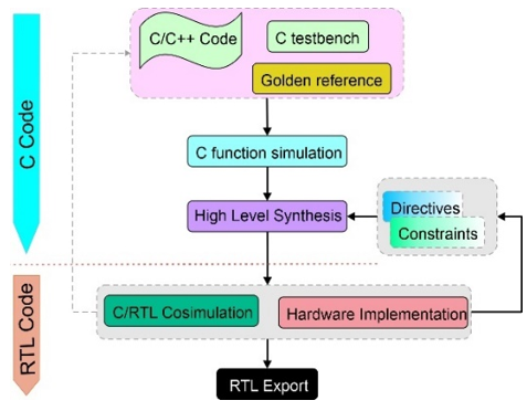
Figure 6. Vitis HLS flow
To speed up the process of making prototypes and make them competitive, we have adopted Xilinx Vitis HLS tools. Figure 6 shows that Vitis HLS can make an RTL design from a function written in a high-level programming language like C, C++, or System C. This is because it works faster and is more flexible than other C-to-FPGA tools of the same type. The design flow followed to get an RTL-HLS IP is illustrated in Figure 6.
The first step starts by developing an HLL code design, a testbench, and a golden reference, representing the estimated outputs for a defined output vector. The second step consists of the functional simulation of the main HLL using the testbench.
4.3.2 LED HLS-IP
For this paper, we used the C/C++ programming language to implement the LED lightweight encryption method. We used Vitis HLS to make the algorithm and test its performance in the RTL design by co-simulating it. The design was then examined and adjusted to enhance throughput.
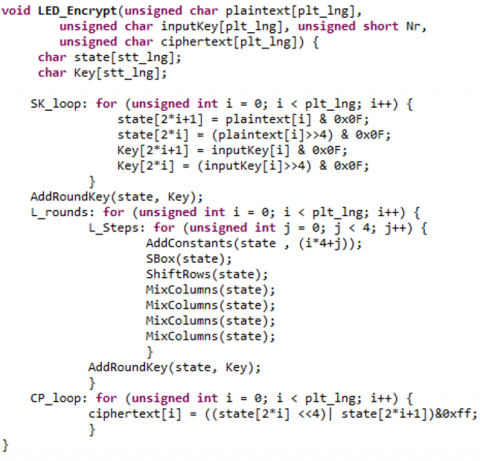
The LED-64 encryption algorithm comprises 32 rounds, as described in Figure 7, and each round is a set of functions, as described in Section 3.2. The HLS-C tool simulated the LED-64 principal function to check the outputs generated compared to the golden reference. Indeed, we use an image sized 512×512 to obtain the encrypted image. After that, with the decrypted image, as soon as the functional simulation step is successfully validated, we go to the synthesis step, which represents the most sensitive step of the design flow since several refinements of the C/C++ code are carried out. After studying the hardware’s performance, the necessary optimizations must be devised. The LED-64 top function was synthesized into an RTL block using the HLS tool, and each sub-function was synthesized into a sub-block that was instantiated into the top-level design.
Figure 7. Encryption LED HLS-IP description
Figure 7 illustrates the LED algorithm code in C/C++. As shown, the HLS model consists of several loop instructions. The first loop is the SK loop, which reads 8 bytes of plaintext and 8 bytes of input keys and separates each byte into two nibbles. We obtain 16 nibbles of the state and 16 nibbles of the key. Afterward, the function AddRoundKey is applied once, which applies the AR loop. The third loop block comprises two nested loops: L rounds and L steps. The L steps loop presents all steps involved during one round of AR loop, SB loop, SR loop, and MC loop. In fact, this inner loop is iterated four times. The L rounds loop describes the 32 rounds performed with LED64 and comprises the LL steps followed by a reminder of an AR loop. In the last loop, the CP loop, all the state nibbles are added to make a ciphertext byte. The LED encryption was simulated with a golden reference and a testbench file. The HLS model is synthesized using the Vitis HLs C synthesis tool to make the RTL description. This will then be exported as hardware intellectual property (IP) so it can be added to the Pynq Project. Once the synthesis step is completed, we proceed to the analysis of design implementation. To improve the performance of our design, we need to analyze and interpret it to find the flaws in how it is currently being used and think of ways to fix them. So, the Xilinx Vitis HLS tool has an option for implementation analysis that lets us check the scheduling of tasks, data routing, and any potential problems like data dependency violations.
This section will discuss how we used Vitis HLS to build and optimize the crypto-watermarking algorithms.
After finishing the LED block cipher synthesis process, we got a Pynq-Z1-based hardware implementation (xc7z020-clg400-1). The Vitis HLS tool makes and builds the HDL model based on the target platform. The synthesis results are detailed and organized according to the chosen performance criterion. As a result, we find performance estimates, utilization estimates, and interface results. We will explore three different implementations of the LED algorithm: 1) initial implementation; 2) unrolled-based optimization; and 3) pipelined-based optimization. During HLS optimization, the LED top function goes through synthesis into an RTL block. At the same time, each subfunction is transformed into a sub-block that is subsequently instantiated into the top-level design. Furthermore, the arguments of the top function are transformed into input/output (I/O) ports. The HLS tool facilitates the selection of the handshaking protocol to be integrated into the input/output (I/O) ports of the designated block(s). Input/output (I/O) ports can be realized through two methods: streaming data from or to a first-in, first-out (FIFO) buffer or reading and writing data to or from memory. The design may call for the implementation of various handshaking protocols.
5.1 Naive implementation
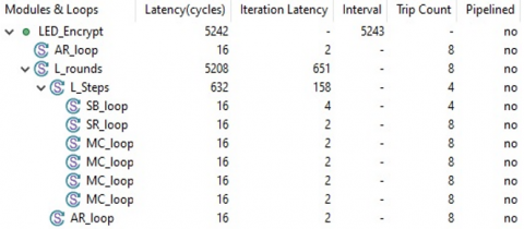
We start with an initial Naive Implementation (NI) according to the software solution without optimization. A primary way to use the LED algorithm has yet to be optimized. In this version, all loops are rolled, and no optimization is applied. As illustrated in Figure 8, already generated by the Xilinx Vitis HLS tool, the overall latency of the LED-decryption circuit is 8988 clock cycles. This considerable delay is because the code was written without any parallelism, pipeline, or duplication of functions. Without optimization, all loops require full processing time to execute their operations. The computation of loop latency involves the multiplication of the iteration latency by the trip count. In order to establish a loop, it is necessary to have one cycle for initiation and another for leaving the loop. This rationale accounts for the inclusion of two additional cycles for all loops. The L-steps loop is examined in the current research, which shows that the four functions are implemented in accordance with the recommended method as mentioned. The L steps are a round comprising the SB, SR, MC, and AR loops. The delay for each loop is calculated by multiplying the iteration latency by the trip count, as shown in Figure 8. We see that 270 clock cycles are needed to complete 1 iteration of L steps, giving 1080 clock cycles to complete 1 step, which equates to 4 rounds. One step needs a total of 1115 cycles to be completed since each loop requires two extra cycles for input and output during execution. The LED encryption HLS-IP exhibits a global execution latency of 8988 for processing a 64-bit block since it is a sequential implementation. Some optimization techniques may be performed to reduce the global latency. In the subsequent implementation, our focus lies on unrolling these functions, intending to mitigate latency.
Figure 8. Vitis HLS report of the naive implementation synthesis
5.2 Unrolled-based optimization
By default, loops are rolled. Each loop iteration corresponds to a “sequence” of states. This sequence will be repeated multiple times based on the loop trip count. The Unrolling Loops (UL) option is a compelling and exciting way to show more parallelism and get a shorter latency. It decreases loop overhead, increases scheduling parallelism, and enables array-to-scalar promotion and continual propagation. However, UL increases operation counts, which may negatively impact the area. The optimization directives were applied to the AddRoundkey, SubBytes, ShiftRows, and MixColumns functions in order to achieve encryption with high throughput and low latency. This technique prioritizes enhancing performance through the utilization of the unrolling loops option. According to its nomenclature, the UNROLL pragma expands a loop by duplicating its core in the Register Transfer Level (RTL) design. This directive enables the concurrent execution of multiple iterations of the loop. The unrolling process can be executed entirely or partially by modifying the duplication factor. In the following subsection, we detail the results of the two solutions, entirely and partially unrolled.
5.2.1 Partially unrolled-based optimization
The present study evaluates the initial implementation, deemed naive, by analyzing the implementation results utilizing the Xilinx Vitis scheduler. This analysis aims to determine which functions can be unrolled and to what extent. Multiple experiments were conducted, wherein the primary setup involved unrolling the SB loop by a factor of 4, while the SR, MC, and AR loops were unrolled by a factor of 2. The results obtained from the Partially Unrolled Implementation (PUI) are illustrated in Figure 9. Focusing on the nested loops with L rounds and L steps, we see that every sub-loop has a delay of 16 cycles, which facilitates the usage of the pipeline technique in the following subsection. The L-step latency is reduced to 632 clock cycles instead of 1080 in the initial implementation. Therefore, the global latency improved by 42%. The reduction factor obtained with partial unrolling depends on the loop structure and the degree of unrolling applied. Generally, increasing the degree of unrolling leads to a higher reduction in latency, which could be even more fascinating. In the next experiment, we will focus on increasing the factor of unroll to achieve higher parallelism and reduce the number of cycles required for execution, which will ultimately lead to faster processing times and improved performance. We will also explore the impact of different unrolling factors on power consumption and resource utilization. The best latency achieved with this optimization was 0.150 ms, which is acceptable compared to our target of 0.4 ms.
Figure 9. Vitis HLS report of the PUI-based optimization synthesis
5.2.2 Entirely unrolled-based optimization
We use a parallel architecture when applying Entirely Unrolled Implementation (EUI), which reduces the latency to 256 clock cycles, as shown in Figure 10. The presence of nested loops is the underlying cause of the latency or interval being experienced. The L-step inner loop exhibits a latency of 7 clock cycles per iteration, resulting in a cumulative total of 28 clock cycles for all iterations. The loop, denoted as L Rounds, exhibits a latency of 30 clock cycles for each iteration. These latencies should be considered when designing the pipeline stages for the processor, as they can significantly impact the system’s overall performance. Additionally, optimizing these loops may reduce the number of clock cycles required for their execution. The speedup compared to partial unrolling and the naive implementation is equal to 52% and 98%, respectively.
Figure 10. Vitis HLS report of the entirely unrolled-based implementation optimization synthesis
Using a parallel architecture is an effective way to optimize the system’s performance. However, it requires carefully considering hardware resources and trade-offs between speed and cost.
5.3 Pipelined-based optimization
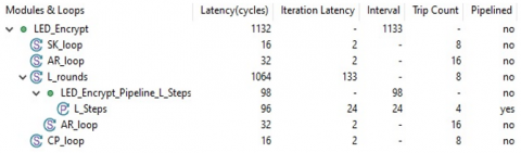
Indeed, one of the required optimization methods for HLS is Loop Pipelining (LP). Before the previous iteration is finished, the LP permits a new one to start processing. The top loop also uses a wholly pipelined loop architecture to reduce latency and hardware costs. This approach allows for more efficient use of resources and faster processing times, making it particularly useful in high-performance computing applications. Additionally, the pipelined architecture allows for better scalability, as more iterations can be added without significantly increasing hardware requirements. We attempt to pipeline the basic implementation (PNI) in this first experiment, as described in Figure 11, the Pipelined-Naive Implementation (PNI). The inner loop L steps with a minimum initiation interval (II) of 24 are subject to the pipeline approach. The new increased latency is 96 clock cycles, which is approximately 91% less latency compared to the 1080 cycles required by the primitive architecture.
Figure 11. Vitis HLS report of the PNI-based optimizations synthesis
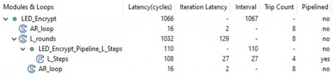
In the second experiment, we based the partial unrolling solution on the fact that all subloops (L rounds and L steps) have equal latencies of 16 clock cycles. By doing so, we were able to reduce the number of cycles required to execute the loop by 80%. This optimization can significantly improve the performance of the co-processor. Figure 12, which presents the Pipelined-Partially Unrolled Implementation (PPUI), shows a global latency of 1066. This improvement in global latency can be attributed to the pipeline’s ability to process multiple instructions simultaneously. However, it is essential to note that this reduction may vary depending on the specific task being performed.
Figure 12. Vitis HLS report of the PPUI-based optimization synthesis
In this section, we evaluate the performance of the suggested approach. The Python 3.8 in a computer Intel(R) Core (TM) i7 CPU Q 720 clocked at 1.60 GHz was used to perform tests on a grayscale standard image and a watermark sized 512×512 and 32×32, respectively.
According to a subjective visual comparison between the watermarked images and the original images in Table 3, the crypto watermarking technique has achieved high imperceptibility. proposed algorithm. As an objective imperceptibility criterion, we computed the PSNR for the cover and watermarked images. The PSNR values are 86.6, 88.9, 90.26, 87.18, and 82.18 for X-ray, MRI, CT, and X-ray high-definition images. These high PSNR values suggest that the images have minimal distortion and are of excellent quality across different categories. For SSIM, the proposed crypto watermarking method also performs well. The NC is equal to 1, which indicates that the extracted watermark is the same as the embedded.
Table 3. Performance results without attack for the proposed method
|
Image |
Size |
PSNR |
SSIM |
NC |
|
X-Ray |
296×296 |
86.6 |
0.9999653 |
1 |
|
MRI |
512×512 |
88.9 |
0.9999785 |
1 |
|
CT |
768×568 |
90.26 |
0.9999845 |
1 |
|
X-Rya |
2496×2048 |
82.18 |
0.9999261 |
1 |
Various voluntary and involuntary image processing attacks may later alter watermarked, decrypted medical images. Therefore, it is crucial to assess the robustness of our suggested approach in an under-attack environment. For these tests, we select the MRI 512×512 medical image against the following attacks: Salt and Pepper noise (SP) with variance 0.02, Gaussian Noise (GN), Median Filter (MF) 3×3, and cropping (CR).
Table 4. Performance results with different attacks for the MRI 512×512 image
|
Attack |
PSNR |
SSIM |
NC |
|
SP |
65.42 |
0.99976 |
0.9678 |
|
GN |
58.51 |
0.99853 |
0.9472 |
|
MF |
51.33 |
0.75931 |
0.8857 |
|
CR |
39.46 |
0.69702 |
0.8545 |
According to the results in Table 4, the suggested scheme has successfully reached a satisfactory outcome. A PSNR average of around 53.68 dB indicates the higher quality of the original and the watermarked image. For SSIM, the proposed crypto watermarking performs well with SP and GN attacks; however, it seems a little degraded for MF and CR attacks, which indicates a little degradation on the extracted watermark.
The robustness is assessed by comparing the original and extracted watermarks' similarity using the NC factor. These show good robustness against SP and GN attacks but are not good for MF and CR attacks. Despite this, the NC values obtained remain superior to 0.75.
Table 5. Comparison of proposed methods
|
Studies |
Ref. [24] |
Ref. [25] |
Ref. [26] |
Proposed |
|
Method |
DCT+DWT |
LSB-HWT |
HWT |
LSB |
|
Encryption |
CS based encryption |
-- |
- |
LED |
|
PSNR |
91.30 |
57.58 |
58 |
90.26 |
|
SSIM |
1 |
1 |
0.9990 |
0.9999 |
|
NC |
1 |
0.9993 |
- |
1 |
To confirm the effectiveness of the proposed crypto watermarking, the comparison of performance with other methods [24-26] is shown in Table 5. The results of this table prove that our scheme has better imperceptibility in comparison with [25, 26]. Furthermore, the performance of the proposed scheme is equivalent to literature [24]. In addition, our scheme also outperforms [25, 26] in terms of robustness against various attacks, as demonstrated in Table 5. This highlights the superiority of our crypto watermarking method not only in imperceptibility but also in its ability to withstand malicious attempts to remove or alter the watermark.
This part evaluates, discusses, and compares the implemented solution’s hardware utilization and performance criteria for the LED encryption/decryption algorithm. To examine the functionality of the RTL design, the Vitis HLS tool synthesized and co-simulated the algorithms. Then, the design was analyzed and optimized to achieve higher throughput. The throughput Tp in this paper is calculated as given in Eq. (5), and the efficiency is calculated by the throughput-to-area ratio as given in Eq. (6).
$T_p=\frac{ { Block } * F max }{ { Latency }}$ (5)
$E f f=\frac{T p}{ { Slices }}$ (6)
In this work, we implemented five HLS versions for the LED cipher as described in Section 5. Table 6 presents a detailed report for all design implementations. We note that the maximum frequency achieved with HLS approaches around 178.49 for the NI, PUI, and EUI architectures. When applying the pipeline technique, the maximal frequencies increase to 208.4 and 231.7 MHz with PNI and PPUI architectures, respectively. For RTL approaches, the maximal frequencies are around 83.8, 98.67, and 167.34 MHz [29-30], respectively.
So, when using the Vitis HLS tool, the frequency is doubled compared to the manual RTL design [28]. Nevertheless, the initial unsophisticated implementation exhibits significant latency, fivefold more remarkable than the RTL implementation. Optimization techniques, such as unrolling and pipelines, were applied to attain optimal latencies. The PPUI and EUI implementations yielded latencies of 1132 and 256 clock cycles, respectively. Regarding resource utilization, it is observed that the manual RTL version [30] and the pipeline-optimized versions exhibit superior performance. Meanwhile, the unrolled versions are characterized by higher logic consumption. This observation suggests that pipeline optimization can effectively improve resource utilization in HLS designs, while unrolling may not always be the best approach due to its higher logic consumption. Further exploration and experimentation could help determine the optimal design strategy for a given application. On the other hand, EUI, PNI, and PPUI HLS methods show better throughput efficiency when compared to RTL, NI, and PUI hardware implementations. These findings suggest that HLS approaches may be more suitable for high-performance computing applications that require fast and efficient processing. However, it is crucial to consider the trade-offs between hardware implementation methods and choose the one that best fits the application’s specific requirements.
The throughput and latency achieved by each solution determine the efficiency of the implementation, favoring the throughput-optimal solutions. Throughput refers to the amount of work that can be completed in a given period, while latency refers to the time it takes to complete a task. Therefore, the most efficient implementation is a solution that can achieve high throughput and low latency.
Table 6. FPGA round-based implementation results of LED block cipher with RTL and Vitis HLS approaches
|
Design Implementation |
Device |
Fmax (MHz) |
Latency (Clock Cycles) |
Resources Utilization |
Tp Mbps |
Eff Tp/Slices |
|||
|
BRAM |
FF |
LUT(s) |
|||||||
|
RTL |
[28] |
Spartan-3 XC3S50-5 |
98.67 |
32 |
- |
77 |
456 |
197.34 |
0.1 |
|
[29] |
Xilinx Spartan 6 |
83.8 |
32 |
- |
211 |
549 |
167.6 |
0.07 |
|
|
[30] |
Spartan-3 XC3S50 -5 |
167.34 |
32 |
- |
70 |
274 |
334.68 |
0.3 |
|
|
Vitis HLS (Our) |
NI |
Pynq Z1 |
177.49 |
280 |
3 |
853 |
720 |
40.56 |
0.015 |
|
PUI |
177.49 |
164 |
0 |
795 |
715 |
69.26 |
0.025 |
||
|
EUI |
177.49 |
8 |
0 |
683 |
701 |
1415 |
0.5 |
||
|
PNI |
208.4 |
35 |
1 |
494 |
658 |
381.07 |
0.15 |
||
|
PPUI |
231.7 |
33 |
1 |
547 |
669 |
449.35 |
0.16 |
||
Table 7. LED encryption/decryption processing time in second (S) based on Pynq Z1
|
Image |
Size |
SW (Pynq Z1) |
HW |
|||||||
|
RTL |
Vitis HLS (Our) |
|||||||||
|
[28] |
[29] |
[30] |
NI |
PUI |
EUI |
PNI |
PPUI |
|||
|
X-ray |
296×296 |
16.87 |
0.11 |
0.13 |
0.067 |
0.55 |
0.32 |
0.015 |
0.06 |
0.0002 |
|
MRI |
512×512 |
50.69 |
0.34 |
0.40 |
0.20 |
1.65 |
0.96 |
0.045 |
0.17 |
0.15 |
|
CT |
768×568 |
83.69 |
0.56 |
0.67 |
0.33 |
2.75 |
1.60 |
0.078 |
0.29 |
0.25 |
|
X-ray |
2496×2048 |
975.62 |
6.67 |
7.85 |
3.89 |
32.26 |
18.81 |
0.91 |
3.47 |
2.93 |
Table 8. Crypto-watermarking Processing time (s) based Pynq Z1
|
Image |
Size |
SW Pynq Z1 |
Total |
LSB (SW)+LED (HW) Pynq Z1 |
Total |
||
|
ENC/EMB |
DEC/EXT |
ENC/EMB |
DEC/EXT |
||||
|
X-ray |
296×296 |
15.46 |
18.6 |
34.06 |
0.15 |
0.29 |
0.44 |
|
MRI |
512×512 |
46.02 |
56.27 |
102.9 |
0.43 |
0.82 |
1.25 |
|
CT |
768×568 |
77.07 |
91.81 |
168.88 |
0.48 |
1.39 |
1.87 |
|
X-ray |
2496×2048 |
893.86 |
1081.6 |
1975.46 |
5.31 |
23.3 |
28.61 |
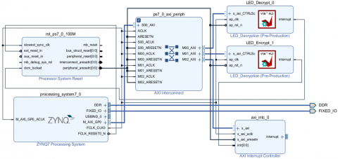
Figure 13. Vivado block design of crypto-watermarking system
The last phase of our work involves conducting processing time measurements and examining the hardware acceleration that was initially intended. This will help us evaluate the efficiency of the hardware acceleration and determine if it meets our performance goals. We can make the necessary adjustments to improve the overall system’s performance based on the results. The various implementations synthesized RTL designs were exported to Vivado, where we achieved the design implementation in preparation for further study. Figure 13 presents the block design of the watermarking system following the Xilinx Viviado tool.
We used the Xilinx Pynq Z1 board, the Xilinx Vivado Design Tool version 2022.2, and Jypiter to conduct the tests and validations. Table 7 summarizes the LED processing time according to all implementation software and hardware. It is evident that the utilization of hardware implementation is more efficient in comparison to software solutions.
The processing time of the crypto-watermarking system is presented in Table 8. The present study explores the utilization of a pure software implementation, namely based on the ARM processor, within an FPGA chip. Additionally, a hybrid implementation approach is investigated, combining the LSB software technique with a hardware solution including LEDs. The obtained results prove the superiority of hardware implementation over software implementation. Hardware implementation offers faster and more efficient processing than software optimization designed to carry out a particular task without additional programming or interpretation. Additionally, hardware implementation can reduce the risk of errors, improve system reliability, and ensure adherence to the real-time constraint. HLS methods have faster processing times and higher throughputs than RTL versions. This is why users choose to implement their designs at the HLS level.
This paper presents a novel hardware/software implementation of crypto-watermarking that utilizes LSB and LED methodologies. This study showcases the acceleration of the LED cipher on an FPGA by implementing unrolling and pipeline optimization techniques, which were used to expedite the entire system. HLS can potentially lead to better throughput in hardware designs because it allows for more efficient optimization and exploration of design alternatives.
The present study comprehensively analyzes the proposed architecture, highlighting its impressive imperceptibility, high-speed, and low-power performance features. The results of this study could have significant implications for developing more efficient and cost-effective LED cipher systems in various applications, such as secure medical communication, data encryption, and IoMT. Further research can be conducted to explore the potential of this architecture in real-world scenarios.
The authors extend their appreciation to the Deputyship for Research & Innovation, Ministry of Education in Saudi Arabia for funding this research work through the project number (IF2/PSAU/2022/01/21316).
[1] Licks, V., Jordan, R. (2005). Geometric attacks on image watermarking systems. IEEE Multimedia, 12(3): 68-78. https://doi.org/10.1109/MMUL.2005.46
[2] Garg, P., Kishore, R.R. (2020). Performance comparison of various watermarking techniques. Multimedia Tools and Applications, 79: 25921-25967. https://doi.org/10.1007/s11042-020-09262-1
[3] Zear, A., Singh, A.K., Kumar, P. (2018). A proposed secure multiple watermarking technique based on DWT, DCT and SVD for application in medicine. Multimedia Tools and Applications, 77: 4863-4882. https://doi.org/10.1007/s11042-016-3862-8
[4] Lee, H.Y. (2019). Adaptive reversible watermarking for authentication and privacy protection of medical records. Multimedia Tools and Applications, 78(14): 19663-19680. https://doi.org/10.1007/s11042-019-7322-0
[5] Haughey, J., Taylor, K., Dohrmann, M., Snyder, G. (2018). Medtech and the internet of medical things: How connected medical devices are transforming health care. Deloitte.
[6] Hasan, M.K., Islam, S., Sulaiman, R., et al. (2021). Lightweight encryption technique to enhance medical image security on internet of medical things applications. IEEE Access, 9: 47731-47742. https://doi.org/10.1109/ACCESS.2021.3061710
[7] Swann, R., Stine, J. (2023). Evaluation of a modular approach to AES hardware architecture and optimization. Journal of Signal Processing Systems, 95: 797-813. https://doi.org/10.1007/s11265-022-01832-w
[8] Prasanalakshmi, B., Murugan, K., Srinivasan, K., Shridevi, S., Shamsudheen, S., Hu, Y.C. (2022). Improved authentication and computation of medical data transmission in the secure IoT using hyperelliptic curve cryptography. The Journal of Supercomputing, 78(1): 361-378. https://doi.org/10.1007/s11227-021-03861-x
[9] Elhamzi, W., Jallouli, M., Bouteraa, Y. (2022). High efficiency crypto-watermarking system based on Clifford-multiwavelet for 3D meshes security. Computers, Materials & Continua, 73(2): 4329-4347. http://doi.org/10.32604/cmc.2022.030954
[10] Araghi, T.K., Abd Manaf, A. (2019). An enhanced hybrid image watermarking scheme for security of medical and non-medical images based on DWT and 2-D SVD. Future Generation Computer Systems, 101: 1223-1246. https://doi.org/10.1016/j.future.2019.07.064
[11] Ghadirli, H.M., Nodehi, A., Enayatifar, R. (2019). An overview of encryption algorithms in color images. Signal Processing, 164: 163-185. https://doi.org/10.1016/j.sigpro.2019.06.010
[12] Zhang, Y., Li, X., Hou, W. (2017). A fast image encryption scheme based on AES. In 2017 2nd International Conference on Image, Vision and Computing (ICIVC), Chengdu, China, pp. 624-628. https://doi.org/10.1109/ICIVC.2017.7984631
[13] Mitra, A., Rao, Y.S., Prasanna, S.R.M. (2008). A new image encryption approach using combinational permutation techniques. International Journal of Computer and Information Engineering, 2(2): 576-580.
[14] Coatrieux, G., Maître, H., Sankur, B., Rolland, Y., Collorec, R. (2000). Relevance of watermarking in medical imaging. In Proceedings 2000 IEEE EMBS International Conference on Information Technology Applications in Biomedicine. ITAB-ITIS 2000. Joint Meeting Third IEEE EMBS International Conference on Information Technol, Arlington, VA, USA, pp. 250-255. https://doi.org/10.1109/ITAB.2000.892396
[15] Khashan, O.A., AlShaikh, M. (2020). Edge-based lightweight selective encryption scheme for digital medical images. Multimedia Tools and Applications, 79(35-36): 26369-26388. https://doi.org/10.1007/s11042-020-09264-z
[16] Das, S., Sunaniya, A.K., Maity, R., Maity, N.P. (2020). Parallel hardware implementation of efficient embedding bit rate control based contrast mapping algorithm for reversible invisible watermarking. IEEE Access, 8: 69072-69095. https://doi.org/10.1109/ACCESS.2020.2986134
[17] Das, S., Singh, P., Koley, C. (2020). Hardware implementation of adaptive feedback based reversible image watermarking for image processing application. Microsystem Technologies, 26(10): 3271-3287. https://doi.org/10.1007/s00542-018-4024-x
[18] Arumugham, S., Rajagopalan, S., Rayappan, J.B.B., Amirtharajan, R. (2019). Tamper-resistant secure medical image carrier: an IWT–SVD–Chaos–FPGA combination. Arabian Journal for Science and Engineering, 44(11): 9561-9580. https://doi.org/10.1007/s13369-019-03883-x
[19] Hazra, S., Ghosh, S., De, S., Rahaman, H. (2018). FPGA implementation of semi-fragile reversible watermarking by histogram bin shifting in real time. Journal of Real-Time Image Processing, 14: 193-221. https://doi.org/10.1007/s11554-017-0672-9
[20] Maity, G.K., Jana, P., Mandal, H., Chiu, T.L. (2019). Power-aware VLSI design of reversible watermarking for access control. Microsystem Technologies, 28: 705-720. https://doi.org/10.1007/s00542-019-04342-1
[21] Phadikar, A., Mandal, H., Chiu, T.L. (2020). Parallel hardware implementation of data hiding scheme for quality access control of grayscale image based on FPGA. Multidimensional Systems and Signal Processing, 31: 73-101. https://doi.org/10.1007/s11045-019-00650-x
[22] Nayak, M.R., Bag, J., Sarkar, S., Sarkar, S.K. (2017). Hardware implementation of a novel water marking algorithm based on phase congruency and singular value decomposition technique. AEU-International Journal of Electronics and Communications: 71: 1-8. https://doi.org/10.1016/j.aeue.2016.10.025
[23] Kaibou, R., Azzaz, M.S., Benssalah, M., Teguig, D., Hamil, H., Merah, A., Akrour, M.T. (2021). Real-time FPGA implementation of a secure chaos-based digital crypto-watermarking system in the DWT domain using co-design approach. Journal of Real-Time Image Processing, 18(6): 2009-2025. https://doi.org/10.1007/s11554-021-01073-3
[24] Borra, S., Thanki, R. (2020). Crypto-watermarking scheme for tamper detection of medical images. Computer Methods in Biomechanics and Biomedical Engineering: Imaging & Visualization, 8(4): 345-355. https://doi.org/10.1080/21681163.2019.1595730
[25] Faheem, Z.B., Ali, M., Raza, M.A., Arslan, F., Ali, J., Masud, M., Shorfuzzaman, M. (2022). Image watermarking scheme using LSB and image gradient. Applied Sciences, 12(9): 4202. https://doi.org/10.3390/app12094202
[26] Yu, Y., Gao, J., Mu, X., Wang, S. (2023). Adaptive LSB quantum image watermarking algorithm based on Haar wavelet transforms. Quantum Information Processing, 22(5): 180. https://doi.org/10.1007/s11128-023-03926-1
[27] Guo, J., Peyrin, T., Poschmann, A., Robshaw, M. (2011). The LED block cipher. In 13th International Workshop, Nara, Japan, pp. 326-341. https://doi.org/10.1007/978-3-642-23951-9_22
[28] Marchand, C., Bossuet, L., Gaj, K. (2017). Area-oriented comparison of lightweight block ciphers implemented in hardware for the activation mechanism in the anti-counterfeiting schemes. International Journal of Circuit Theory and Applications, 45(2): 274-291. https://doi.org/10.1002/cta.2288
[29] Marchand, C., Bossuet, L., Gaj, K. (2017). Ultra-lightweight implementation in area of block ciphers. Foundations of Hardware IP Protection, pp. 177-203. https://doi.org/10.1007/978-3-319-50380-6_9
[30] Al-Shatari, M., Hussin, F.A., Abd Aziz, A., Witjaksono, G., Rohmad, M.S., Tran, X.T. (2019). An efficient implementation of LED block cipher on FPGA. In 2019 First International Conference of Intelligent Computing and Engineering, Hadhramout, Yemen, pp. 1-5. https://doi.org/10.1109/ICOICE48418.2019.9035193
[31] Chest X-Ray Images (Pneumonia) DataSet from Kaggle. https://www.kaggle.com/datasets/paultimothymooney/chest-xray-pneumonia, accessed on Apr. 17, 2022.
[32] Brain_Tumor_Detection_MRI DataSet from Kaggle. https://www.kaggle.com/abhranta/brain-tumor-detection-mri, accessed on Feb. 22, 2022.
[33] Breast Ultrasound Images Dataset (BUSI) DataSet from Kaggle. https://www.kaggle.com/datasets/sabahesaraki/breast-ultrasound-images-dataset, accessed on Feb. 22, 2022.
[34] Bogdanov, A., Knudsen, L.R., Leander, G., Paar, C., Poschmann, A., Robshaw, M.J.B., Seurub, Y., Vikkelsoe, C. (2007). PRESENT: An ultra-lightweight block cipher. In 9th International Workshop, Vienna, Austria, pp. 450-466. https://doi.org/10.1007/978-3-540-74735-2_31
[35] Vitis High-Level Synthesis User Guide. https://usermanual.wiki/m/eff365c5fddc5d1e84992bdad1c02d45d7b2ecfbeb9af6f50b5dd79dd2f973f7.
[36] Sussmann, M., Hill, T. (2017). Intel HLS compiler: Fast design, coding, and hardware. White Paper.
[37] Ralphs, T.K., Guzelsoy, M., Mahajan, A. (2015). SYMPHONY 5.6. 9 User’s Manual. SYMPHONY. https://www.coin-or.org/SYMPHONY/doc/SYMPHONY-5.6.9-Manual.pdf.