Turki M. Alanazi![]()
© 2023 IIETA. This article is published by IIETA and is licensed under the CC BY 4.0 license (http://creativecommons.org/licenses/by/4.0/).
OPEN ACCESS
This paper presents an accelerated implementation of the Vector Directional Filter (VDF) on a Field Programmable Gate Array (FPGA) for real-time denoising of color images. The VDF effectively suppresses noise while preserving edges and fine details, making it ideal for a range of applications such as satellite and multispectral biomedical imaging. However, the filter's high computational complexity poses challenges for real-time processing. Existing solutions either fail to meet real-time execution requirements or compromise image quality through hardware implementation approximations. To overcome these challenges, we first model the VDF using C/C++ programming, and subsequently design an efficient floating-point hardware architecture employing the High-Level Synthesis (HLS) flow. Optimal directives are selected using the Xilinx Vivado HLS tool. The VDF architecture is then integrated as a coprocessor with the Cortex-A53 hardcore processor in the XCZU9EG FPGA. To enhance data bandwidth between software and hardware components, three Direct Memory Access (DMAs) units are utilized to transfer three image lines in parallel. Furthermore, internal memory is implemented on the XCZU9EG FPGA, providing increased flexibility for managing the restored image. The VDF Software/Hardware (SW/HW) design's robustness and accuracy are validated through experimental studies on the ZCU102 board. Our design accelerates the filtering process by 21 times, maintaining visual quality and effectively removing noise from color images compared to the VDF SW design. Additionally, our solution outperforms existing approaches in terms of filtered image quality and processing time, showing a 24% improvement in the worst-case scenario.
nonlinear filter, vector directional filter, color image, noise reduction, SW/HW codesign, FPGA
Various applications, such as medical imaging and remote sensing, necessitate the processing of color images for accurate visual scene interpretation [1, 2]. Color images are created, edited, transmitted, and stored, often becoming corrupted by noise in the process. Noise degradation not only impairs the visual quality of images but also affects subsequent image processing tasks, such as edge detection and feature extraction [3, 4]. Consequently, numerous filters have been proposed for denoising color images while preserving image features and details [5-7]. Among these, nonlinear filters are particularly important due to their compatibility with the nonlinear human perception system and proven efficacy in eliminating noise without introducing significant distortion in color images [8, 9]. A prominent subclass of nonlinear vector filters is based on robust order-statistics, with the Vector Median Filter (VMF) [10] and the Vector Directional Filter (VDF) [11, 12] being the most well-known examples.
The VDF operates directionally on image vectors, removing vectors with atypical directions in the RGB space and achieving optimal chromaticity estimations. As a result, the VDF better preserves chromaticity compared to the VMF [13-15]. However, the VDF's directional processing requires complex mathematical operations, such as vector dot products, vector norms, and angle calculations. Additionally, the VDF operates in multidimensional space, demanding substantial computational resources and making real-time implementation challenging. Therefore, it is essential to reduce the VDF's computational complexity without compromising its noise removal capabilities.
Various strategies have been employed by researchers to minimize the complexity of nonlinear filters. For instance, in the study [16], a software implementation of the VDF on the Texas Instruments DSP TMS320C6711 using floating-point operations is proposed, achieving a 320×320 image filtering time of 1342 at 150 MHz. In the study [17], the VDF algorithm is approximated for implementation on an Intel Pentium® processor running at 2.66 GHz, reducing processing time but sacrificing filtered image quality. Another study [18] presents a fixed-point Software/Hardware (SW/HW) implementation of the VDF employing approximations for the nonlinear function. The SW component is executed by the NIOS II softcore processor, resulting in a faster filtering process but decreased reconstructed image quality. In the study [19], sequential and parallel hardware architectures are developed for the Adaptive Vector Median Filter (AVMF) using an approximated method, with a relative inaccuracy of 0.01% compared to ideal SW implementations. However, the VDF implementations in the studies [16, 17] fail to satisfy real-time processing requirements, while the design in the study [18] leads to diminished denoised image quality.
The density of Field Programmable Gate Arrays (FPGAs) has increased over time, enabling hardware implementation of complex applications across various fields, such as IoT systems [20], video processing [21, 22], and neural networks [23]. To reduce the design complexity of FPGAs, High-Level Synthesis (HLS) flow can be employed instead of Low-Level Synthesis (LLS) flow, allowing for efficient exploration of an algorithm's design space and increased designer productivity [24, 25]. In this work, the HLS flow is utilized to develop an optimized VDF design and implement it within a SW/HW codesign environment. The proposed architecture aims to balance hardware resources and processing time while maintaining visual quality and effectively removing noise from color images. To achieve this, the Xilinx Vivado design tool is used to develop and integrate the HLS VDF design as a coprocessor with the ARM processor. The SW/HW design is implemented on the Zynq XCZU9EG FPGA and evaluated on the ZCU102 board. The general objective of the SW/HW codesign environment is to leverage the flexibility of the software component and the performance of the hardware component through parallelism and pipeline techniques.
The remainder of this paper is organized as follows: Section 2 provides an overview of the VDF. Section 3 details the HLS flow used to generate the VDF hardware design. Section 4 discusses the implementation of the VDF within the SW/HW environment, while Section 5 presents the experimental findings. Finally, Section 6 concludes the paper.
The VDF works on the direction of the color vectors with the purpose of removing vectors with atypical directions. The output vectors ( $y(n)$ ) of the VDF are determined by Eq. (1) [11].
$y(n)=\operatorname{Argmin}\left(\propto_i\right)$ (1)
The function Argmin determines the value that minimizes the angle between all pixels in the filter window which are presented by $x_1, x_2, \ldots, x_N$ (N presents the filter window size). Indeed, the angular distance ( $\propto_i$ ) related with an input pixel $\chi_i$ from the filter window is calculated by Eq. (2) [11].
$\propto_i=\sum_{i=1}^N A_{i j}\left(x_i, x_j\right), i=1,2, \ldots, N$ (2)
where, $A\left(x_i, x_j\right)$ represents the angle between two input vectors $\chi_i=\left(R_i, G_i, B_i\right)$, $x_j=\left(R_j, G_j, B_j\right)$ as illustrated by Eq. (3) [11].
$A\left(x_i, x_j\right)=\arccos \left(\frac{x_i x_j^T}{\left\|x_i\right\| \cdot\left\|x_j\right\|}\right)$ (3)
Thus, the output of the VDF is the vector $x_{(1)}$ from the input vectors which related to the lowest weighted angular distance $\propto_{(1)} \in\left\{\propto_{(1)} \leq \propto_{(2)} \leq \cdots \leq \propto_{(N)}\right\}$. However, the vector $x_{(1)}$ is obtained by $x_{(1)} \leq x_{(2)} \leq \cdots \leq x_{(N)}$.
A number of HLS tools have recently been introduced, including the Xilinx Vivado HLS tool, which allows users of a software languages (e.g., C/C++, SystemC) to produce various hardware designs for any algorithm. Indeed, the Vivado HLS tool allows for the use of a variety of directives to produce an optimal design. For example, the RESOURCE directive is used to optimize the implementation of the array by using the memories or registers. On the other hand, the PIPELINE directive can be applied to the loop iterations to decrease the latency time and increase the throughput.
Figure 1 illustrates the HLS design of the VDF created through the Vivado HLS V18.1 from the C/C++ software code. Figure 2 presents the principles of the VDF design. Indeed, various directives (e.g., RESOURCE, PIPLINE, and PARTITION) are applied to the VDF code to produce different VDF hardware designs to be implemented on the Zynq XCZU9EG FPGA. Nevertheless, Table 1 and Figure 3 illustrate the FPGA resources, which are presented by the number of Flip-Flops (FFs), Look-up-table (LUTs), DSP, and memory blocks (BRAMs). On the other hand, Figure 3 presents the clock cycle number. By the way, our objective is to choose the best design that enables us to reduce the hardware resources and accelerate the processing time of the VDF algorithm.
Figure 1. HLS design of the VDF
As shown in Figure 1, the VDF design gets three RGB pixels from three image lines at the same time. Once the filter window (3×3 pixels) is constructed, the process of filtering the noisy RGB pixel is started by computing the angle Aij (xi, xj) between two pixels. After that, the angular distance αi associated with an input xi is calculated based on Eq. (2). The comparator is then used to calculate the RGB pixel related to the minimum weighted angular distance once the nine angular distances are available. In the end, the filtered pixel is stored in the internal RAM memory to restore the image. This process is repeated through the loop iteration until all pixels in the N×N noisy color image are filtered, as depicted in Figure 2.
Table 1. Design summary for the VDF architectures
|
|
LUTs |
FFs |
BRAM_18K |
DSP48E |
|
Design 1 |
16142 (5%) |
7512 (1%) |
122 (1%) |
35 (6%) |
|
Design 2 |
17928 (6%) |
9757 (1%) |
120 (1%) |
41 (6%) |
|
Design 3 |
364985 (133%) |
109746 (20%) |
184 (18%) |
338 (10%) |
|
Design 4 |
98403 (35%) |
34942 (6%) |
121 (13%) |
1001 (6%) |
Figure 2. Principle of the VDF design
Figure 3. Hardware resources of the VDF
In the beginning, the VDF algorithm is synthesized through Vivado HLS V18.1 without using any directives. The synthesis results of design 1 for the VDF show that this design needs 1% of FFs, 5% of LUTs, 1% of DSPs, and 6% of BRAMs, as depicted in Figure 3. Furthermore, as seen in Figure 4, 2133306378 clock cycles are required to restore a noisy image. As a result of these observations, it appears that the clock cycle number is unusually high. Thus, to reduce this number, the filter window is divided into 24-bit register blocks for parallel data access by using the PARTITION directive. In this case, design 2 is created, which allows a small decrease of 1% of clock cycles and an increase of 10% of the LUTs. It is apparent that the cycle number is usually high. But it is preferred to use the PARTITION directive to increase the performance of the PIPELINE directive by allowing simultaneous access to the data. Thus, design 3 is created by applying the PIPELINE directive to loop 3, which is presented in Figure 1. In fact, this loop needs more time than loops 1 and 2. Nevertheless, the synthesis results of design 3 show a dramatic reduction in the clock cycle number by 99% relative to design 2, as depicted in Figure 4. But this design exceeds the number of LUTs available on the FPGA, as reported in Figure 3. Indeed, by using the PIPELINE directive, the synthesis tool can pipeline the loop and execute multiple iterations in parallel, which improves the overall throughput and performance of the circuit. But, pipelining a loop requires additional hardware resources such as registers, adders, and multiplexers, which leads to increased overall resource utilization of the design. So, by using the PIPELINE directive, design 3 made extensive use of hardware resources, which resulted in exceeding the number of LUTs available in the FPGA. The RESOURCE directive, on the other hand, is a feature in HLS tools that is used to guide the HLS tool in making resource allocation decisions during the synthesis process and ensure generating an optimized design in terms of area cost. Therefore, design 4 is created by adding the RESOURCE directive to implement the 3×3 filter window using the memory block and also optimize the FPGA cost. From Figures 3 and 4, we can see that design 4 provides a gain of 68% of FFs, 73% of LUTs, 28% of DSPs, and 34% of BRAMs, but with a decrease of 93% of the clock cycles compared to design 3. Thus, it is clear that the use of the RESOURCE directive can ensure a significant improvement in hardware resource allocations. Further, design 4 gives a gain of 99% in clock cycles while increasing the amount of hardware resources by 72% of FFs, 82% of LUTs, and 88% of DSPs in comparison to design 2, as shown in Figures 3 and 4, respectively. Consequently, design 4 provides a compromise between the hardware resources and the processing time and presents the best design for the VDF.
Figure 4. Clock cycles of the VDF
The SW/HW implementation of the VDF is realized on the Zynq XCZU9EG FPGA. This FPGA implements the ARM Cortex-A53 as a hardcore processor in the Processing System (PS) part. This processor is a 64-bit Harvard RISC processor clocked at 1.2GHz, where the sizes of the L1 and L2 cache memories are 32KB and 1MB, respectively. The PS employs the industry-standard AXI (Advanced eXtensible Interface) interface to connect with the Programmable Logic (PL) part. By the way, two interfaces are provided by the standard AXI, which are the AXI4-Lite and the AXI4-Stream [26, 27].
The SW/HW design suggested for the VDF is shown in Figure 5. The VDF coprocessor and the DDR memory are connected utilizing three Direct Memory Access (DMA1, DMA2, and DMA3) through the AXI-Stream interface, as depicted in Figure 5.
Figure 5. SW/HW architecture for the VDF
Figure 6. 3×3 RGB filtering window
In fact, our objective is to increase the data throughput by transferring three image lines simultaneously to construct the 3×3 filter window (Figure 6). For that, DMA1 is set up in write and read modes. In contrast, DMAs 2 and 3 are only set up in read mode. Therefore, when the filter window is constructed through these three DMAs, the VDF coprocessor starts looking for the RGB pixel associated with the least weighted angular distance and saves it in the internal memory to restore the image. As seen in Figure 6, the next filter window is created by adding only three RGB pixels. Thus, each pixel filtered by the VDF will be stored in the internal memory to construct the whole image, which is then transferred to the PS part through the DMA1.
The SW/HW VDF design is implemented and assessed on the ZCU102 board [28]. The Vivado tool V18.1 establishes the FPGA resources of the proposed design on the Zynq XCZU9EG FPGA. According to Figure 7, our design uses 37227 (7%) FFs, 87210 (32%) LUTs, 338 (13%) DSP blocks, and 63 (7%) BRAMs.
Figure 7. SW/HW VDF design resources
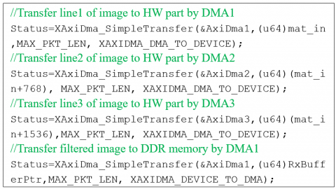
Figure 8 presents the evaluation flow of the SW/HW codesign system. In fact, according to this figure, the developed VDF C/C++ code is compiled in standalone mode by the Xilinx Software Development Tool Kit (SDK) by using the hardware specification imported from the Xilinx Vivado tool as a bitstream file (.bit). The generated software binary file (.elf) is uploaded with the bitstream file to the FPGA. The SD card is used to store the contaminated images with noise and collect the filtered images, which are provided by our SW/HW codesign system. However, the header file "ff. h" is added to the software code (C/C++) to create a file system on the SD card, as depicted in Figure 9. Figure 10 illustrates the instructions employed to read and write data from and to an SD card. Therefore, as shown in Figure 11, four lines of C/C++ code are added to our VDF code to control the read and write data between the VDF coprocessor and the DDR memory using three DMAs. In fact, the addresses of the 1st line, 2nd line, and 3rd line of the image are provided to the DMA1, DMA2, and DMA3, respectively, to transfer image pixels in parallel to the VDF coprocessor. Besides, when the filtered image is ready, the DMA1 commences to transfer the filtered pixels to the DDR memory.
The SW/HW VDF design's performance is measured with regard to the image quality and the processing time. For that, the SD card is used to store various test standard color images (e.g., Sailboat, Lena, Mandrill, Monalisa, and Peppers). These images have a resolution of 256×256 pixels and are corrupted by 3% "salt and pepper" impulsive noise and Gaussian noise with σ=5. These noises may appear during transmission, scanning, medical imaging, and other processes. Additionally, the ARM cortex-A53 processor's timer is employed to measure the processing time. In fact, the timer module in the Cortex-A53 includes four 64-bit timers, which can be used to measure time intervals through the header file "xtime_l.h". This file provides access to the 64-bit physical timer counter via the XTime_GetTime() function to read the current value of the XTime timer before and after calling function(). Then, the time is computed by subtracting the start time from the end time and dividing by the number of timer ticks per second. Besides, image quality is assessed using commonly used objective metrics [29, 30], such as the Peak Signal to Noise Ratio (PSNR) and the Normalized Color Difference (NCD).
Tables 2 and 3 show the processing time and image quality (NCD and PSNR metrics) of the SW and SW/HW designs of the VDF. As represented in Table 2, the VDF SW/HW design may accelerate the restoration of the image by 21 times compared to the SW design, allowing for a 95% decrease in processing time. As illustrated in Table 3, the improvement in processing time is obtained with no change in image quality between the SW and SW/HW designs in terms of PSNR and NCD for impulsive and Gaussian noises. Furthermore, it is justified by subjective measurement, as seen in Figure 12. In fact, there is no visible distinction between images restored by the SW and those restored by the SW/HW design. We may conclude from the experiment findings that the SW/HW design is more performant than the SW design, despite the fact that floating-point is employed for the hardware VDF implementation via the HLS flow, demonstrating the correctness of the proposed VDF SW/HW design.
Figure 8. Evaluation flow of the SW/HW codesign system
Figure 9. File management by the “ff. h” library
Figure 10. Instructions for read/write data from/to SD card
Figure 11. Control read/write data by the DMAs from the DDR memory
Table 4 compares the performance of the VDF design to that of the literature. We can observe from the table that our solution outperforms [16] and [17], which provide software implementations of the VDF on the DSP TMS320C6711@150MHz and the Intel Pentium@2.66GHz, respectively. Furthermore, our design outperforms [18] in processing time and image quality. In fact, [18] presents a fixed-point SW/HW architecture for the VDF, which employs the NIOS II processor to process the software part and the VHSIC (Very Speed Hardware Description Language) Hardware Description Language (VHDL) for HW implementation. Thus, our design allows a reduction of 24% in processing time relative to [18], despite the fact that it uses a floating-point implementation.
Table 2. Processing time measurement for the VDF designs
|
|
SW |
SW/HW |
|
Processing time (ms) |
1500 |
72 |
Table 3. Measurement of the NCD and PSNR for VDF designs
|
Images |
Impulsive noise |
Gaussian noise |
||||||
|
NCD |
PSNR (dB) |
NCD |
PSNR (dB) |
|||||
|
SW |
SW/HW |
SW |
SW/HW |
SW |
SW/HW |
SW |
SW/HW |
|
|
Sailboat |
0.10337 |
0.10337 |
25.46 |
25.46 |
0.11035 |
0.11035 |
25.97 |
25.97 |
|
Lena |
0.04135 |
0.04135 |
28.84 |
28.84 |
0.05443 |
0.05443 |
29.16 |
29.16 |
|
Mandrill |
0.08286 |
0.08286 |
21.12 |
21.12 |
0.09092 |
0.09092 |
21.06 |
21.06 |
|
Monalisa |
0.02998 |
0.02998 |
29.35 |
29.35 |
0.05901 |
0.05901 |
28.29 |
28.29 |
|
Peppers |
0.05358 |
0.05358 |
27.61 |
27.611 |
0.05775 |
0.05775 |
30.65 |
30.65 |
Table 4. Performance comparison of various VDF designs
|
Ref. |
Size of image |
Processing time (ms) |
Specifications |
Implementation |
|
[18] |
176×144 |
41 |
NIOS II/VDF@70MHz |
Fixed-point |
|
[16] |
320×320 |
1342 |
DSP TMS320C6711@150MHz |
Floating-point |
|
[17] |
512×512 |
306 |
Intel pentium@2.66GHz |
|
|
Proposed design |
176×144 |
31 |
A53@1.2GHz/VDF@100MHz |
|
|
256×256 |
72 |
|||
|
512×512 |
226 |
Figure 12. (1) Original images, (2) noise intensity (3%), restored images with (3) SW and (4) SW/HW designs
The SW/HW implementation of the VDF is proposed in this study. An optimal VDF HW architecture is developed via the HLS flow using Vivado HLS V18.1. By the way, numerous directives (PARTITION, RESOURCE, and PIPELINE) are integrated in the VDF C++ code. Then, in the SW/HW codesign environment, this architecture is incorporated as a coprocessor with the ARM Cortex-A53 hardcore processor. The AXI-stream is used by DMA to increase data bandwidth between the VDF coprocessor and the DDR memory. In the end, the performance study on the ZCU102 board shows that the SW/HW design reduces the processing time by 95% when compared to the SW design with the same filtered image quality and outperforms the solution proposed in the literature.
[1] Rashid, N., Berriri, K., Albekairi, M., Kaaniche, K., Ben Atitallah, A., Khan, M.A., El-Hamrawy, O.I. (2022). New real-time impulse noise removal method applied to chest x-ray images. Diagnostics, 12(11): 2738. https://doi.org/10.3390/diagnostics12112738
[2] Said, Y., Atri, M., Albahar, M.A., Ben Atitallah, A., Alsariera, Y.A. (2023). Scene recognition for visually-impaired people’s navigation assistance based on vision transformer with dual multiscale attention. Mathematics, 11(5): 1127. https://doi.org/10.3390/math11051127
[3] HosseinKhani, Z., Hajabdollahi, M., Karimi, N., Soroushmehr, R., Shirani, S., Najarian, K., Samavi, S. (2018). Adaptive real-time removal of impulse noise in medical images. Journal of Medical Systems, 42: 1-9. https://doi.org/10.1007/s10916-018-1074-7
[4] Gökcen, A., Kalyoncu, C. (2020). Real-time impulse noise removal. Journal of Real-Time Image Processing, 17: 459-469. https://doi.org/10.1007/s11554-018-0791-y
[5] Smolka, B. (2018). Robust sharpening vector median filter. In 2018 International Automatic Control Conference (CACS). IEEE, pp. 1-6. https://doi.org/10.1109/CACS.2018.8606777
[6] Roy, A., Singha, J., Manam, L., Laskar, R.H. (2017). Combination of adaptive vector median filter and weighted mean filter for removal of high‐density impulse noise from colour images. IET Image Processing, 11(6): 352-361. https://doi.org/10.1049/iet-ipr.2016.0320
[7] Roy, A., Manam, L., Laskar, R.H. (2018). Region adaptive fuzzy filter: An approach for removal of random-valued impulse noise. IEEE Transactions on Industrial Electronics, 65(9): 7268-7278. https://doi.org/10.1109/TIE.2018.2793225
[8] Ahamed, B.B., Yuvaraj, D., Priya, S.S. (2019). Image denoising with linear and non-linear filters. In 2019 International Conference on Computational Intelligence and Knowledge Economy (ICCIKE). IEEE, pp. 806-810. https://doi.org/10.1109/ICCIKE47802.2019.9004429
[9] Solovyeva, E. (2017). Cellular neural network as a non-linear filter of impulse noise. In 2017 20th Conference of Open Innovations Association (FRUCT). IEEE, pp. 420-426. https://doi.org/10.23919/FRUCT.2017.8071343
[10] Astola, J., Haavisto, P., Neuvo, Y. (1990). Vector median filters. Proceedings of the IEEE, 78(4): 678-689. https://doi.org/10.1109/5.54807
[11] Trahanias, P.E., Venetsanopoulos, A.N. (1993). Vector directional filters-a new class of multichannel image processing filters. IEEE Transactions on Image Processing, 2(4): 528-534. https://doi.org/10.1109/83.242362
[12] Lukac, R., Smolka, B., Plataniotis, K.N., Venetsanopoulos, A.N. (2004). Selection weighted vector directional filters. Computer Vision and Image Understanding, 94(1-3): 140-167. https://doi.org/10.1016/j.cviu.2003.10.013
[13] Celebi, M.E., Kingravi, H.A., Aslandogan, Y.A. (2007). Nonlinear vector filtering for impulsive noise removal from color images. Journal of Electronic Imaging, 16(3): 033008-033008. https://doi.org/10.1117/1.2772639
[14] Chanu, T.R., Singh, T.R., Singh, K.M. (2021). A survey on impulse noise removal from color image. Turkish Journal of Computer and Mathematics Education (TURCOMAT), 12(13): 4274-4295.
[15] Vishnu Tej, Y., James Stephen, M., Prasad Reddy, P.V.G.D., Choppala, P. (2022). A novel methodology for denoising impulse noise in satellite images through isolated vector median filter with k-means clustering. International Journal of Engineering Trends and Technology, 70(8): 272-283. https://doi.org/10.14445/22315381/IJETT-V70I8P229
[16] Domínguez, L.C., Ponomaryov, V.I. (2005). Nonlinear filters for colour imaging implemented by DSP. In 2005 2nd International Conference on Electrical and Electronics Engineering. IEEE, pp. 81-84. https://doi.org/10.1109/ICEEE.2005.1529578
[17] Celebi, M.E. (2009). Real-time implementation of order-statistics-based directional filters. IET Image Processing, 3(1): 1-9. https://doi.org/10.1049/iet-ipr:20080080
[18] Atitallah, A.B., Boudabous, A., Khriji, L., Masmoudi, N. (2013). Reconfigurable architecture of VDF filter for multidimensional data. International Journal of Circuit Theory and Applications, 41(10): 1047-1058. https://doi.org/10.1002/cta.1815
[19] Ben Atitallah, A., Abid, I., Boudabous, A., Loukil, H. (2021). A new hardware architecture of the adaptive vector median filter and validation in a hardware/software environment. International Journal of Circuit Theory and Applications, 49(8): 2329-2347. https://doi.org/10.1002/cta.3000
[20] Zhang, X., Ramachandran, A., Zhuge, C., He, D., Zuo, W., Cheng, Z., Rupnow, K., Chen, D. (2017). Machine learning on FPGAs to face the IoT revolution. In 2017 IEEE/ACM International Conference on Computer-Aided Design (ICCAD), pp. 894-901. https://doi.org/10.1109/ICCAD.2017.8203875
[21] Alanazi, T.M., Atitallah, A.B. (2022). Unified FPGA design for the HEVC dequantization and inverse transform modules. Computers, Materials & Continua, 71(3). https://doi.org/10.32604/cmc.2022.022988
[22] Kthiri, M., Le Gal, B., Kadionik, P., Atitallah, A.B. (2013). A very high throughput deblocking filter for H. 264/AVC. Journal of Signal Processing Systems, 73: 189-199. https://doi.org/10.1007/s11265-013-0744-4
[23] Chen, Y., He, J., Zhang, X., Hao, C., Chen, D. (2019). Cloud-DNN: An open framework for mapping DNN models to cloud FPGAs. In Proceedings of the 2019 ACM/SIGDA International Symposium on Field-Programmable Gate Arrays, pp. 73-82. https://doi.org/10.1145/3289602.3293915
[24] Ben Atitallah, A., Kammoun, M., Ali, K.M., Ben Atitallah, R. (2020). An FPGA comparative study of high‐level and low‐level combined designs for HEVC intra, inverse quantization, and IDCT/IDST 2D modules. International Journal of Circuit Theory and Applications, 48(8): 1274-1290. https://doi.org/10.1002/cta.2790
[25] Ye, H., Jun, H., Yang, J., Chen, D. (2023). High-level synthesis for domain specific computing. In Proceedings of the 2023 International Symposium on Physical Design, pp. 211-219. https://doi.org/10.1145/3569052.3580027
[26] Atitallah, A.B., Kammoun, M., Atitallah, R.B. (2020). An optimized FPGA design of inverse quantization and transform for HEVCdecoding blocks and validation in an SW/HW environment. Turkish Journal of Electrical Engineering and Computer Sciences, 28(3): 1656-1672. https://doi.org/10.3906/elk-1910-122
[27] Atitallah, M.A.B., Kachouri, R., Atitallah, A.B., Mnif, H. (2022). An efficient HW/SW design for text extraction from complex color image. CMC-Computers, Materials & Continua, 71(3): 5963-5977. https://doi.org/10.32604/cmc.2022.024345
[28] UltraScale, X.Z. (2019). Xilinx Zynq UltraScale+MPSoC ZCU102 evaluation kit. MPSoC ZCU102 Evaluation Kit.
[29] Ben Atitallah, A. (2022). A new adaptive filter to remove impulsive noise in color images. IEEJ Transactions on Electrical and Electronic Engineering, 17(7): 1048-1053. https://doi.org/10.1002/tee.23594
[30] Russo, F. (2014). Performance evaluation of noise reduction filters for color images through normalized color difference (NCD) decomposition. International Scholarly Research Notices, 2014. http://dx.doi.org/10.1155/2014/579658