OPEN ACCESS
This work investigates the advantages that can be gained through the proper integration between a thermal solar module and a small-scale gasification system. The gasification power plant here studied consists in a PP20 Power Pallet, a complete power plant capable of 20 kW of electrical power. Fresnel lens concentrated thermal solar panel system is used as heat source for the gasification power plant. Different scenarios are drafted looking at the different way the heat can be provided. One scenario investigates the use of solar heat to dry the gasifier fuel (wood chips). It is proven that dried fuel allows a reduced tar production in gasification systems as well as an increase in the gasification efficiency. A second scenario investigates the possibility of pre-heating the air used as gasification agent. Air pre-heating produces a higher temperature combustion zone, with higher chance to perform a better thermal cracking of the tarry compounds yielded by the pyrolysis zone. Results show that the solar unit is capable of air preheating up to 149 °C, nevertheless the efficiency increase that derives from this solution is little when compared with the use of heat for wood chips drying.
biomass, gasification, combined heat and power, solar thermal
Renewable sources utilization is mandatory for a sustainable growth of the planet comprehending an efficient CO2 content reduction in the atmosphere [1]. However, the energy produced by solar and wind technologies is affected by a great variability, thus creating issues on the electrical grid [2]. A stable, renewable and programmable energy production is required to meet end-user load profiles [2], technologies such as biomass power plants are suitable for it [3].
Among them, gasification is an efficient technology able to convert a solid fuel into a gaseous one [4-5]. Wood residues and agro-forestry by-products can be efficiently used as fuel for gasification (i.e. vine prunings [6], poplar wood chips [7-8], corn cobs [9], corn stover [10-11], wood residues from river maintenance [12], solid residues from vegetable oil production [13], solid residues from cotton crops [14], municipal green waste [15] etc.). Produced gas obtained can be used as fuel in internal combustion engines, turbines, heat generators, high temperature fuel cells etc. [5, 16-17].
Most of commercial gasification systems rely on auto-thermal processes, where the heat required to sustain three over four of the gasification phases (drying, pyrolysis, char reduction) is provided by the combustion phase [5]. For this reason, any solution addressed to the heat recovery, reactor insulation or external heat supply, can positively increase the gasification efficiency through a reduction of the energy required by the combustion zone [18].
Literature reports few studies regarding energy optimization in gasification. For example, Wu and Chein calculated an increase of the gasifier cold gas efficiency from 74 % to 81 % using pre-heated air at 500 °C as gasifying agent [19], preheated air can be generated using engine exhaust heat [20]. Wu and Chein studied also the influence of biomass moisture on gasifier performance, they calculated a decreases of cold gas efficiency from 84 % to 69 % passing from dry biomass to biomass with 40 % of moisture [19].
The insulation behavior on a lab scale up-draft gasifier was evaluated by James et al. [21]. An experimental study regarding air pre-heating to 350 °C in an Imbert type downdraft gasifier reports an increase of the cold gas efficiency of the gasifier from 51.5 % to 59.6 % [22]. In [23] an air jacket is used in internal air heating process increasing the efficiency of the gasifier and the heating value of the producer gas. Raman et al. used a heat exchanger to pre-heat the gasification air cooling down the outlet producer gas [24].
This paper simulates the integration between two renewable technologies: solar thermal power and small scale wood biomass gasification. Several studies report this integration where the solar energy is used to drive the gasification giving the external energy required to sustain the reaction [25]. In this paper solar energy is used for two purposes: gasification air pre-heating and biomass drying. The solar driven drying system is design in order to reduce the biomass moisture from 30 % to 15 % wet basis. The same solar system was used to simulate air-preheating to 149 °C. Producer gas heating value, gasifier efficiency and electrical power production were calculated in both cases considering steady state conditions. A comparison between these scenarios and the conventional one without solar integration was reported.
2.1 Gasifier model
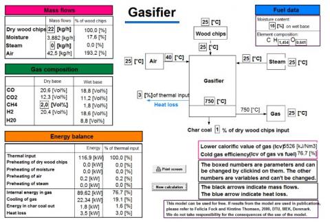
To simulate the efficiency of an Imbert downdraft gasifier, a software developed by the Denmark Technical University (DTU) in 2000 was used [26]. This simple software has a simple user-friendly interface which, starting from multiple INPUTS, is capable of simulating the operation of a downdraft gasifier, giving accurate results as outputs. Model inputs are:
Gasification maximum temperature, which is one of the main features that determines the Syngas composition, is set to 750 [4].
The overall efficiency, may be influenced by slightly modifying the input values. As a matter of fact, by reducing the moisture content of the woodchips, an increase of the quality of the syngas immediately follows [4]. Designing a rotary dryer for the biomass, coupled to a solar thermal panel is the main aim of this study.
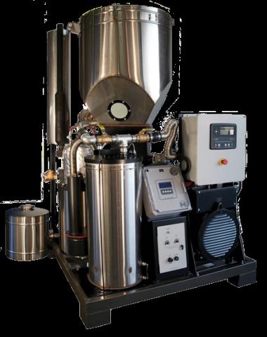
The gasifier simulated in this work is a 20 kWel gasifier-engine pilot plant. The model chosen is the PP20 Power Pallet (Figure 1), manufactured by the company ALL Power Labs [27]. The system is composed of a fuel hopper of about 0.33 m3 of volume, an auger biomass moving system from the hopper to the reactor, a single throat downdraft fixed bed gasifier provided with a filtration stage and an IC engine linked to a gen-head for electrical power production. Table 1 resumes the main features of the Power Pallet (depicted in Figure 1) [27].
Table 1. Main technical specifications of the PP20 [27]
|
Gasifier |
Imbert Downdraft |
|
Biomass |
Woodchips G30 |
|
Biomass flow |
24 kg/h |
|
Syngas flow |
60 m3/h |
|
IC Engine |
GM Vortec 3.0 l |
|
Electrical Generator |
Mecc Alte NPE32-E/4 12 |
Figure 1. PP20 power pallet gasifier [24]
The biomass fuel used in the simulation is fir wood chips; the HHV is evaluated by the formula suggested by Channiwala [28]:
$HH{{V}_{db}}=349.1{{C}_{db}}+1178.3{{H}_{db}}+100.5{{S}_{db}}+103.4{{O}_{db}}+15.1{{N}_{db}}+21.1AS{{H}_{db}}$ (1)
where C, H, N, S, O [%wt.] are the weight fractions of the respective elements, ASH [%wt.] is the ash content in the dry sample. Table 2 resumes the elemental composition of the biomass taken from Ref. [29].
Table 2. Elemental composition of Biomass [26]
|
Input |
Value (% dry-basis) |
|
ASH |
0.3 |
|
C |
50.4 |
|
H |
6.1 |
|
N |
0.1 |
|
S |
0.01 |
|
O |
43.1 |
In Table 3 the pre-fixed features of the Gasifier are listed. Moisture Content is 30 % only on the scenario without pre-treatment of the biomass fuel.
Table 3. Gasifier simulation input data
|
Input |
Value |
|
Dry wood Temperature [ Tp ] |
25°C |
|
Moisture Content [M.C.] |
30 % |
|
Dry Wood mass flow [$\dot{M}_S$] |
0.00667 kg/s |
|
Gas. Air Temperature [Ta] |
40°C |
|
Atmospheric Temperature |
25°C |
For a mass balance of the air flow necessary to gasify the incoming biomass, an Equivalent Ratio value of 0.25 is used [18]. This means that, in order to obtain syngas from 1 kg of biomass, around 1.625 kg of gasifying air is needed. Figure 2 illustrates a screenshot taken from the software, the little squares are the space for inputting the variables.
Figure 2. Screenshot of the software’s main interface [26]
2.2 Dryer and heat exchanger model
In order to improve the overall efficiency of the gasifier, a complementary system consisting of the following component was modeled:
Solar thermal heating modules “MCT” by Chromasun [30]
Rotary dryer vehiculating biomass directly into the hopper
Cross-flow Heat exchanger
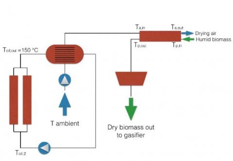
The plant layout is depicted in Figure 3.
Figure 3. Complementary system layout
The mean fluid circulating in the ‘solar’ circuit is a diathermic oil “THERMINOL 66” having a specific heat of 1.86 kJ/(kg ℃) [31]. A blower pumps air inside the cross-flow heat exchanger, this air will be conveyed to the dryer in a counter-flow configuration with the wood chips.
The main calculations to be solved are the ones for the heat exchanger and the dryer. As Figure 3 depicts, biomass and air are counter flowing, the mass flow of the total weight of the biomass (product) IN and OUT is calculated through the following equations:
${{\dot{M}}_{IN}}={{\dot{M}}_{s}}(1+A{{H}_{s,IN}})$ (2)
${{\dot{M}}_{OUT}}={{\dot{M}}_{s}}(1+A{{H}_{s,OUT}})$ (3)
The Absolute Humidity (AH) content for the biomass is evaluated in Equations 4 and 5:
$A{{H}_{s,OUT}}=\frac{{{{\dot{M}}}_{{{H}_{2}}O,OUT}}}{{{{\dot{M}}}_{S}}}$ (4)
$A{{H}_{s,IN}}=\frac{{{{\dot{M}}}_{{{H}_{2}}O,IN}}}{{{{\dot{M}}}_{S}}}$ (5)
where ${{\dot{M}}_{s}}$ is the mass flow of the dry weight of the biomass and ${{\dot{M}}_{{{H}_{2}}O}}$ is the mass flow of the water content inside the biomass. On the other hand, mass flows for the air:
${{\dot{F}}_{IN}}={{\dot{M}}_{A}}+{{\dot{M}}_{V,IN}}$ (6)
${{\dot{F}}_{OUT}}={{\dot{M}}_{A}}+{{\dot{M}}_{V,OUT}}$ (7)
Absolute Humidity for the vapor-air mixture as known (${{\dot{M}}_{a}}$ dry air net flow, ${{\dot{M}}_{v}}$ steam flow):
$A{{H}_{OUT}}=\frac{{{{\dot{M}}}_{v,OUT}}}{{{{\dot{M}}}_{a}}}$ (8)
$A{{H}_{IN}}=\frac{{{{\dot{M}}}_{v,IN}}}{{{{\dot{M}}}_{a}}}$ (9)
The mass balance for the H2O consists in a mass flow equation balancing the Moisture content leaving the biomass and entering the air flow:
${{\dot{M}}_{s}}\left( A{{H}_{s,IN}}-A{{H}_{s,OUT}} \right)={{\dot{M}}_{a}}\left( A{{H}_{OUT}}-A{{H}_{IN}} \right)$ (10)
In other words ${{\dot{M}}_{a}}$ is the mass flow strictly necessary to bring a ${{\dot{M}}_{s}}$ flow between the wanted values of Absolute Humidity of the biomass. It is important to point out that the $A{{H}_{OUT}}$ of the air flowing out of the dryer must be lower than it’s saturation value $(A{{H}_{SAT}})$ at the outgoing air temperature. The temperature trends inside the dryer can be evaluated by exploiting the similarity with a counter-current heat exchanger [32]:
$\dot{Q}=UA\Delta {{T}_{ml}}$ (11)
$\Delta {{T}_{ml}}=\frac{\Delta {{T}_{1}}-\Delta {{T}_{2}}}{1n{}^{\Delta {{T}_{1}}}/{}_{\Delta {{T}_{2}}}}$ (12)
Keeping the biomass at a constant temperature throughout the process will assure that the heat is being used only for the evaporation of the moisture content, and not to overheat (and most likely torrefying) the wood chips. Furthermore, it is recommended not to completely dry up the biomass for the same reason. The amount of heat necessary for the M.C. to evaporate, with R indicating the latent heat of evaporation is calculated with Equation 13:
$Q={{\dot{M}}_{s}}\left( A{{H}_{s,IN}}-A{{H}_{s,OUT}} \right)R$ (13)
The energy balance equation for the dryer involves enthalpy variations for the following: air flow (steam+dry air), M.C. flow and dry biomass flow. Equation 14 contains these 3 power loads and it equals exactly the amount of heat power that the dryer needs from the outside.
${{\dot{Q}}_{est}}={{\dot{M}}_{A}}({{J}_{OUT}}-{{J}_{IN}})+{{\dot{M}}_{s}}{{c}_{p,s}}\left| {{T}_{p,OUT}}-{{T}_{p,IN}} \right|+{{\dot{M}}_{s}}{{c}_{p,H2O}}(A{{H}_{s,OUT}}{{T}_{p,OUT}}-A{{H}_{s,IN}}{{T}_{p,IN}})$ (14)
${{J}_{OUT}}$ and ${{J}_{IN}}$ are the initial and final enthalpies of the air, ${{T}_{p,OUT}}$ and ${{T}_{p,IN}}$ final and inital temperature of the biomass, ${{c}_{p,H2O}}$ and ${{c}_{p,s}}$ [kJ/kg °C] specific heat capacities of water and biomass.
Considering the dryer an adiabatic system ${{\dot{Q}}_{est}}=$0, then Equation 10 and 14 can be linked used to compose a linear system:
$\left\{ \begin{align} & {{{\dot{M}}}_{s}}\left( A{{H}_{s,IN}}-A{{H}_{s,OUT}} \right)={{{\dot{M}}}_{A}}\left( A{{H}_{OUT}}-A{{H}_{IN}} \right) \\ & {{{\dot{M}}}_{A}}({{J}_{OUT}}-{{J}_{IN}})+{{{\dot{M}}}_{s}}{{c}_{p,s}}\left| {{T}_{p,OUT}}-{{T}_{p,IN}} \right|+{{{\dot{M}}}_{s}}{{c}_{p,H2O}}(A{{H}_{s,OUT}}{{T}_{p,OUT}}-A{{H}_{s,IN}}{{T}_{p,IN}})=0 \\ \end{align} \right.$ (15)
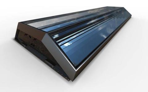
By defining the IN and OUT temperatures of the drying air, respectively Ta,IN=110 °C and Ta,OUT=40°C, ${{J}_{IN}}$ and ${{J}_{OUT}}$ [kJ/kg] are calculated, and by solving the system, the air mass flow ${{\dot{M}}_{A}}$ [kg/s] and absolute humidity of the air leaving the dryer AHOUT can be evaluated. The AHIN is calculated assuming a starting value of relative humidity for atmospheric air of 50 % at 25 °C. To generate the heat necessary to operate the dryer, the thermal fluid flows into the Micro Solar Thermal generators. The Chromasun MCT in Figure 4 is rated under the SRCC Standard 600 "Test Methods and Minimum Standards for Concentrating Collectors” [33].
Chromasun MCT is subsequently certified under OG-100 which is the principal rating for all solar collectors in the United States, it has achieved the highest temperature rating ever tested at a constant of 179 °C. With 20 reflecting Fresnel lenses inside a dimensionally limited panel (3.3 m x 1.2 m x 0.21 m), this module is extremely easy to carry and install within a Micro-solar generation plant.
The nominal technical characteristics of a single MCT panel are listed in Table 4. The output temperature that was used in the calculations is Toil,OUT=150 °C, in order to have a conservative result, taking in account that the panel is exposed to a variable radiation during operation hours.
Table 4. MCT technical data
|
Peak Th.OUT at DNI 1000 W/m2 |
2 kW |
|
Max Toil,OUT |
200 °C |
|
Weight |
100 kg |
|
Dimensions |
3.3m x 1.2m x 0.31m |
|
Fluid Flow $[{{\dot{M}}_{oil}}]$ |
0.113 kg/s |
The cross-flow heat exchanger can be designed if the power transferred between air and oil is known [32]:
$\dot{Q}={{\dot{M}}_{a}}{{c}_{p,a}}({{T}_{a,IN}}-{{T}_{atm}})$ (16)
$\dot{Q}={{\dot{M}}_{oil}}{{c}_{p,oil}}({{T}_{oil,2}}-{{T}_{oil,OUT}})$ (17)
$\Delta {{T}_{mlfi}}=F\Delta {{T}_{ml}}$ (18)
$\dot{Q}=UA\Delta {{T}_{mlfi}}$ (19)
where ${{c}_{p,a}}$ [kJ/kg °C] is the specific heat capacity of the air, ${{c}_{p,oil}}$ [kJ/kg °C] specific heat capacity of the oil [31], ${{T}_{oil,2}}$ temperature of the “cold” oil ricirculating inside the panels. Using Equation 16, the thermal power exchanged can be evaluated and, consequently, acknowledge how many 2 kW panels can efficiently dry a specific ${{\dot{M}}_{s}}$ [kg/s] biomass flow from 30 % M.C. down to 15 % M.C.
Equation 17 is used to calculate the temperature of the oil recirculating back into the solar panels ${{T}_{oil,2}}$ [°C].
To design the Heat Exchanger the F correcting factor [33] is applied to normalize the logarithmic delta (Equation 18), which is calculated using Equation 12. An exchange surface can be finally evaluated using Equation 19 setting global thermal exchange unit U=30 [32]
Figure 4. MCT Solar Panel [30]
The efficiency increase of the Gasifier depends on the specific data input; as a matter of fact, 2 different scenarios were analyzed:
In Case B, the dryer is not contemplated. The system is therefore much simpler. Furthermore, another distinction between the 2 is the different “use” of the hot air mass flow. In case A, the dryer fixes the ${{\dot{M}}_{A}}$ that is needed to dry the biomass, in case B, on the other hand, the gasification air is heated up directly and it’s mass flow depends on a mass balance of the gasifier [4]. The power load necessary to heat the ${{\dot{M}}_{a}}$ [kg/s] flowing in the dryer to a temperature of Ta,IN=110 °C, which is calculated with Equation 15 to be necessary to dry a biomass flow ${{\dot{M}}_{s}}$=0.00667 kg/s, is 3.95 kW .The net surface in the Heat Exchanger needed to carry out the transfer from the solar fluid to the drying air is calculated using Equation 19. Table 5 shows the results.
Table 5. Case A
|
|
Value |
|
${{\dot{M}}_{a}}$ |
0.0562 kg/s |
|
$\dot{Q}$ |
3.95 kW |
|
AHOUT |
0.0365 kgv/kga |
|
AHsat@40℃ |
0.0488 kgv/kga |
|
A |
0.00212 m2 |
It is important to point out that absolute humidity of the drying air exiting the dryer is lower than the saturation value at 40 °C, this prevents the steam in the humid air to condensate back again in the biomass in the last section of the rotating drum. The results in terms of power load needed, and the capacity of 2 kW for each MCT panel, make it necessary to install 2 units for a correct operation of the system. The increase of the producer gas LHV and gasifier CGE, compared to a not pre-treated biomass, is reported in table 6.
Table 6. Case A efficiency results
|
|
LHV [kJ/N m3] |
CGE[%] |
|
Case A |
5526 |
76.7 |
|
No pre-treatment |
4718 |
70.4 |
For Case B, the air mass flow heated to 149 °C (this is the maximum temperature because the operating value for the Solar fluid as communicated by manufacturer is 150 °C) is regulated by mass balance of the stoichiometric gasification air (1 kg of biomass fuel is gasified by 1.625 kg of air) [4], This value is reported in Table 7 together with the power load needed by the heat exchanger (no dryer used in case B).
Table 7. Case B
|
|
Value |
|
${{\dot{M}}_{a}}$ |
0.0110 kg/s |
|
$\dot{Q}$ |
1.37 kW |
|
A |
0.00186 m2 |
Case B lays a much simpler scenario; only 1 MCT unit is needed to generate the heat necessary to raise the air temperature to the desired (and maximum) value. The heat exchanging surface is not considerably lower, so the heat exchanger used is the same as in case A. On the other hand, efficiency of the syngas is dramatically lower compared to case A. Table 8 shows the comparison of the results.
Table 8. Case comparison efficiency results
|
|
LHV [kJ/Nm3] |
CGE[%] |
|
Case A |
5526 |
76.7 |
|
Case B |
4871 |
71.9 |
|
No pre-treatment |
4718 |
70.4 |
The producer gas, after being filtrated, flows into the IC engine of the PP20 unit. The overall productivity increase in terms of electrical power output as shown in Table 9. In the calculations, engine efficiency is set to 0.25 and generator efficiency is set to 0.85 as suggested by the manufacturer [27].
Table 9. Case A efficiency results
|
|
M.C. 30% |
Case A |
Case B |
|
LHV biomass [MJ/kg] |
18.079 |
18.079 |
18.079 |
|
Biomass mass flow [kg/s] |
0.0067 |
0.0067 |
0.0067 |
|
CGE [%] |
70.4 |
76.7 |
71.9 |
|
Producer gas chemical power [kW] |
78.3 |
90.3 |
84.1 |
|
IC engine mechanical power [kW] |
19.6 |
22.6 |
21 |
|
Generator net Electrical power [kW] |
16.6 |
19.2 |
17.85 |
Power output increase of the Power Pallet is mainly linked to a decrease of the humidity content of the biofuel. The heat necessary to pre-treat the incoming humid biomass, is balanced, in the gasifying process, with a sensible increase in efficiency of the reactor.
This result opens a wide scenario of possible layouts of a Micro power generation from biomass, with a low increase of installation complexity (and cost). On the other hand, the choice not to dry the biomass, simplifies the layout even more, but has poor results in terms of efficiency increase. Furthermore, the heat exchange surface needed to heat the gasifying air is not distant enough from the first case to justify a sensible reduction in the dimensions of the Heat Exchanger. A micro solar like the MCT, limits the operating temperature of it’s mean fluid, and, consequently, the maximum temperature that can be reached by the gasifying air.
[1] European Commission (2019). Reflection paper: Toward a Sustainable Europe by 2030. 30 January 2019. Available: https://ec.europa.eu/commission/files/reflection-paper-towards-sustainable-europe_en
[2] Liserre M, Sauter T, Hung, J. (2010). Future energy systems: Integrating renewable energy sources into the smart power grid through industrial electronics. IEEE Industrial Electronics Magazine 4(1): 18-37. https://doi.org/10.1109/MIE.2010.935861
[3] IEA, IEA Bioenergy Annual Report 2018 April 2019. Available: https://www.ieabioenergy.com/publications/iea-bioenergy-annual-report-2018/
[4] Basu P, Biomass Gasification and Pyrolysis – Practical design and theory – Third Edition. Oxford, UK: Elsevier, 2018.
[5] Malaguti V, Lodi C, Sassatelli M, Pedrazzi S, Allesina G, Tartarini P. (2017). Dynamic behavior investigation of a micro biomass CHP system for residential use. International Journal of Heat and Technology 35(S1): 172-178. https://doi.org/10.18280/ijht.35Sp0124
[6] Allesina G, Pedrazzi S, Puglia M, Morselli N, Allegretti F, Tartarini P. (2018). Gasification and wine industry: Report on the use vine pruning as fuel in small-scale gasifiers. in European Biomass Conference and Exhibition Proceedings 26thEUBCE 722-725. https://doi.org/10.5071/26thEUBCE2018-2CV.2.19
[7] Allesina G, Pedrazzi S, Tartarini P. (2013). Modeling and investigation of the channeling phenomenon in downdraft stratified gasifers. Bioresource Technology 146: 704-712. https://doi.org/10.1016/j.biortech.2013.07.132
[8] Pedrazzi S, Allesina G, Tartarini P. (2012). Aige conference: A kinetic model for a stratified downdraft gasifier. International Journal of Heat and Technology 30(1): 41-44. https://doi.org/10.18280/ijht.300106
[9] Allesina G, Pedrazzi S, Sgarbi F, Pompeo E, Roberti C, Cristiano V, Tartarini P. (2015). Approaching sustainable development through energy management, the case of Fongo Tongo, Cameroon. International Journal of Energy and Environmental Engineering 6(2): 121-127. https://doi.org/10.1007/s40095-014-0156-7
[10] Allesina G, Pedrazzi S, Montermini L, Giorgini L, Bortolani G, Tartarini P. (2014). Porous filtering media comparison through wet and dry sampling of fixed bed gasification. Journal of Physics: Conference Series 547(1): 012003. https://doi.org/10.1088/1742-6596/547/1/012003
[11] Allesina G, Pedrazzi S, Guidetti L, Tartarini P. (2015). Modeling of coupling gasification and anaerobic digestion processes for maize bioenergy conversion. Biomass and Bioenergy 81: 444-451. https://doi.org/10.1016/j.biombioe.2015.07.010
[12] Pedrazzi S, Allesina G, Morselli N, Puglia M, Barbieri L, Lancellotti I, Ceotto E, Giorgini L, Malcevschi A, Pederzini C, Tartarini P. (2017). The energetic recover of biomass from river maintenance: The REBAF project. In European Biomass Conference and Exhibition Proceedings, 25thEUBCE, pp. 52-57. https://doi.org/10.5071/26thEUBCE2018-2CV.2.7
[13] Allesina G, Pedrazzi S, Tebianian S, Tartarini P. (2014). Biodiesel and electrical power production through vegetable oil extraction and byproducts gasification: Modeling of the system. Bioresource Technology 170: 278-285. https://doi.org/10.1016/j.biortech.2014.08.012
[14] Allesina G, Pedrazzi S, Allegretti F, Morselli N, Puglia M, Santunione G, Tartarini P. (2018). Gasification of cotton crop residues for combined power and biochar production in Mozambique. Applied Thermal Engineering 139: 387-394. https://doi.org/10.1016/j.applthermaleng.2018.04.115
[15] Pedrazzi S, Santunione G, Minarelli A, Allesina G. (2019). Energy and biochar co-production from municipal green waste gasification: A model applied to a landfill in the north of Italy. Energy Conversion and Management 187: 274-282. https://doi.org/10.1016/j.enconman.2019.03.049
[16] Pedrazzi S, Allesina G, Tartarini P. (2016). Effects of upgrading systems on energy conversion efficiency of a gasifier - fuel cell - gas turbine power plant. Energy Conversion and Management 126: 686-696. https://doi.org/10.1016/j.enconman.2016.08.0489
[17] Rinaldini CA, Allesina G, Pedrazzi S, Mattarelli E, Savioli T, Morselli N, Puglia M, Tartarini P. (2017). Experimental investigation on a Common Rail Diesel engine partially fuelled by syngas. Energy Conversion and Management 138: 526-537. https://doi.org/10.1016/j.enconman.2017.02.034
[18] Reed TB, DAS A. (1994). Handbook of biomass gasifier engine systems – 2th ed. Golden, CO: Biomass Energy Foundation Press.
[19] Wu KT, Chein RY. (2015). Modeling of biomass gasification with preheated air at high temperatures. Energy Procedia 75: 214-19. https://doi.org/10.1016/j.egypro.2015.07.307
[20] Zhang P, Ma T, Li WD, Ma GY, Wang QW. (2018). Design and optimization of a novel high temperature heat exchanger for waste heat cascade recovery from exhaust flue gases. Energy 160: 3-18. https://doi.org/10.1016/j.energy.2018.06.216
[21] James AM, Yuan W, Boyette MD, Wang D. (2018). Airflow and insulation effects on simultaneous syngas and biochar production in a top-lit updraft biomass gasifier. Renewable Energy 117: 116-124. https://doi.org/10.1016/j.renene.2017.10.034
[22] Guangul FM, Shaharin A, Sulaiman SA, Ramli A. (2012). Gasifier selection, design and gasification of oil palm fronds with preheated and unheated gasifying air. Bioresource Technology 126: 224-232. https://doi.org/10.1016/j.biortech.2012.09.018
[23] Olgun H, Ozdogan S, Yinesor G. (2011). Results with a bench scale downdraft biomass gasifier for agricultural and forestry residues. Biomass- Bioenergy 35(1): 572-80. https://doi.org/10.1016/j.biombioe.2010.10.028
[24] Raman P, Ram NK, Gupta R. (2013). A dual fired downdraft gasifier system to produce cleaner gas for power generation: design, development and performance analysis. Energy 54: 302-314. https://doi.org/10.1016/j.energy.2013.03.019
[25] Loutzenhiser PG, Muroyama AP. (2017). A review of the state-of-the-art in solar-driven gasification processes with carbonaceous materials. Solar Energy 156: 93-100. https://doi.org/ 10.1016/j.solener.2017.05.008
[26] Fock F, Thomsen KPB, Houbak N, Henriksen UB. (2000). Modelling a biomass gasification system by means of EES. In Proceedings of SIMS Conference Lyngby, pp. 179-186.
[27] All Power Labs Inc. PP20 datasheet. April 2019. Available: http://www.allpowerlabs.com/products/20kw-power-pallets
[28] Channiwala S, Parikh P. (2002). A unified correlation for estimating HHV of solid, liquid and gaseous fuels. Fuel 81(8): 1051-1063. https://doi.org/10.1016/S0016-2361(01)00131-4
[29] Galeno G. (2007). Modellizzazione di un micro cogeneratore basato sulla tecnologia MCFC accoppiata ad un gassificatore di Biomassa. Ph.D. dissertation, Dept. Industrial Eng., Univ. ff Cassino, IT, 2007.
[30] Chromasun Inc. (2019). Chromasun MCT solar panel datasheet. April 2019. Available: http://chromasun.com/images/content/resources/MCT_Thermal_Product_Spec_201106.pdf
[31] Eastman Inc. (2019). Therminol 66 heat transfer fluid data sheet. April 2019. Available: https://www.therminol.com/sites/therminol/files/documents/TF-08_Therminol_66.pdf
[32] Cengel YA, Turner R, Cimbala J. (2016). Fundamentals of Thermal-Fluid Sciences - 5th edition. New York, US: McGraw-Hill Education.
[33] Chromasun Inc. (2019). MCT Solar panel certification SRCC. April 2019. Available: http://chromasun.com/images/content/resources/SRCC_Certification.jpg