Emad Toma Karash*![]() | Muna Y. Slewa
| Muna Y. Slewa![]() | Bushra Habeeb AL-Maula
| Bushra Habeeb AL-Maula![]()
© 2023 IIETA. This article is published by IIETA and is licensed under the CC BY 4.0 license (http://creativecommons.org/licenses/by/4.0/).
OPEN ACCESS
Dental restorations that successfully bind to dental tissue and cosmetically mimic the tooth are in higher demand. Dental professionals can reconstruct posterior teeth using inlays/onlays, which combine functional and anatomical factors with aesthetic considerations. Inlays/onlays are made of porcelain and resin with no metallic basis. In this research, cases of deformation and the distribution of different stresses and strains for a tooth second upper molar crown were studied by designing four two dimensional mathematical models, the first for a tooth made of natural materials, and for the other three mathematical models of teeth with fillings from different materials (Zirconia, Titanium, Ceramic), and impact force was applied in three places, the first in the middle the filling and the second in the contact area between the filling and the tooth, and the third force shed between the first force and the second force. The results showed that the least deformation was in the model containing the zircon filler, while the highest deformation was in the model containing the ceramic filler. As well as from the important results, it was found that the model containing the ceramic filler is in a suitable fit with the model of the natural tooth in terms of the distribution of stresses, strains and deformation.
titanium, ceramic, composite material, zirconia, dental, fillings, stress, enamel, strain
Is there anything more beautiful than a bright white smile? Is there anything that makes you more charming and attractive than healthy, clean teeth? All people dream of having a smile like the smile of movie stars, but there are many problems that must be solved first to reach that dream. The most important and widespread of these problems is the problem of tooth decay, which, if not treated early, may develop and form voids and collapses, what is the solution to fill these gaps and restore full teeth? They are dental fillings. Cosmetic fillings are one of the most common cosmetic procedures used in dentistry, whether for therapeutic or cosmetic purposes. Dental fillings not only help restore teeth and restore their attractive shape, but also play a role in fighting bacteria, as the filling clogs the places where colonies of bacteria that cause decay and erosion used to live. The materials used in cosmetic dental fillings include a number of possibilities such as gold, porcelain, composite, and amalgam (an alloy of mercury, silver, copper, tin, and zinc). Composite fillings are the most beautiful type of fillings at all, in order to match their color with the color of your original teeth, making a subtle invisible. Dental composites chemically interact with the teeth, increasing the level of support and strengthening the tooth structure. This type is not used only when tooth decay. Cob set fillings are used to repair decayed teeth and fill voids or in front tooth fillings. This type of coating does not require large particles of tooth enamel like amalgam fillings, which increases safety. This study's objective was to assess how the sintering temperature affected the mechanical characteristics of PICN dental zirconia and to compare those mechanical characteristics to those of other PICNs. In comparison to conventional dental ceramic materials, PICN dental materials' mechanical properties, such as bending strength, elastic modulus, fracture toughness, and stiffness, were more akin to those of natural teeth and were influenced by density and sintering temperature. SEM showed that the porous ceramic network became coherent and that the incision length in the PICN dental material was reduced [1-5]. Restoration systems that use these materials are based on dental adhesive [6-8]. An alternate approach to the dental restoration issue is to simulate the procedure mathematically using finite element analysis [9, 10]. Different Various studies were performed to investigate the failure behavior of individual repair materials and the stress distribution pattern using finite element analysis (FEA) [11-17].
According to the finite element models, resin restorations experience higher levels of stress than porcelain restorations when subjected to coupled thermomechanical loading. Therefore, when selecting the material for aesthetically repairing posterior teeth, clinical practitioners should bear this aspect in mind [18]. Different Various studies were performed to investigate the failure behavior of individual repair materials and the stress distribution pattern using finite element analysis (FEA) [19-28].
In this research, five mathematical models of ceramic dental fillings with different densities will be designed to find out the amount of deflection and stresses and distribute them on these fillings using a program SNSYS 15.0. The reason for choosing this topic is to find new materials to be used in fillings instead of traditional materials, in addition to creating materials that have high resistance and are compatible with the human body.
After that, the article is continued in the other paragraphs: Materials and Model Analysis, Results and Discussion, Conclusions and future work, Acknowledgment, and References.
This study came to several key conclusions, one of which is that varied fillings allowed for the identification of deformation cases and the distribution of stresses and strains across the dental crown. In addition, the tooth containing the ceramic filler and when a vertical force was applied in the area of contact of the tooth with the filling were the two places in the models with fillings that experienced the maximum deformation.
In order to investigate the stresses, strains, and deformations of the various fillings that occur when a large load is imposed on them, four two-dimensional models of fillings for the second coronary tooth were created using the finite element method and the ANSYS 15.0 program. The materials that make up the first model are Enamel, the second model is made of Zircon, the third model is made of Titanium, and the fourth model is made of Ceramics. Comparisons will be made between the four models' outcomes.
Figure 1 shows the dimensions of these models and the places of vertical forces imposed on the composite fillings on the tooth. According to the formula for calculating flexural strength (ISO 6872) [2].
Four two-dimensional mathematical models were designed consisting of a crown upper second molar tooth with a filling, the first mathematical model is a natural tooth made of natural materials, in the second mathematical model the filling was made of zircon, and in the third mathematical model the filling was made of titanium, and in the fourth mathematical model the filling was made of ceramic. In each model, an impact vertical force was applied in three different places on each filling, the first force was applied (F1) in the middle of the filling, and the second force (F2) was applied between the middle and end of the filling, while the third force (F3) was applied at the point of contact of the filler with the crown upper second molar tooth. The mechanical characteristics of the materials chosen for the construction of the three two-dimensional mathematical models are shown in Table 1. A force of magnitude (300 N) was applied perpendicular to the composite filling on the crown upper second molar tooth.
Figure 1. The three mathematical models used in the test
Table 1. Modulus of elasticity and poisson's ratio of materials used in creating mathematical models for dental crowns and fillings [3, 4, 5, 18, 19, 20]
|
No. |
Material |
Modulus of Elacity E, GPa |
Poisson's Ratio |
|
1 |
Bone |
13.7 |
0.3 |
|
2 |
Gold Alloy |
96.6 |
0.3 |
|
3 |
Titanium |
110 |
0.35 |
|
4 |
Dentin |
18.6 |
0.31 |
|
5 |
Ceramic |
96 |
0.29 |
|
6 |
Composite Resin |
8.3 |
0.28 |
|
7 |
Enamel |
84 |
0.33 |
|
8 |
Zirconia |
210 |
0.34 |
After completing the four models, which consisted of three different materials (natural tooth, Zirconia, Titanium, Ceramic), the forces in each model were applied in three different places on the fillings. After that, the necessary tests were carried out for the four models using the ANSYS 15.0 program to study the deformation and stress and strain states in all the models and compare them. All models were designed to two-dimensional and the thickness was considered one unit in all models.
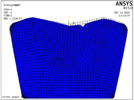
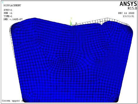
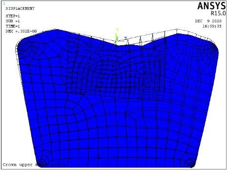
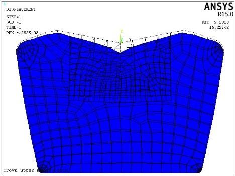
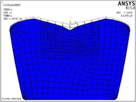
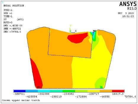
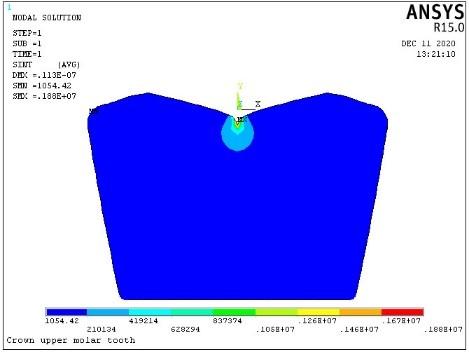
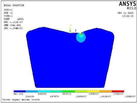
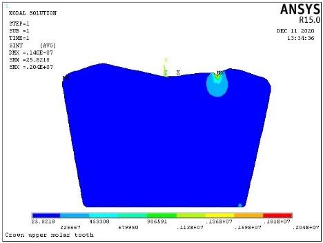
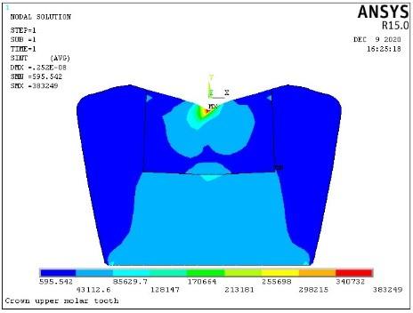
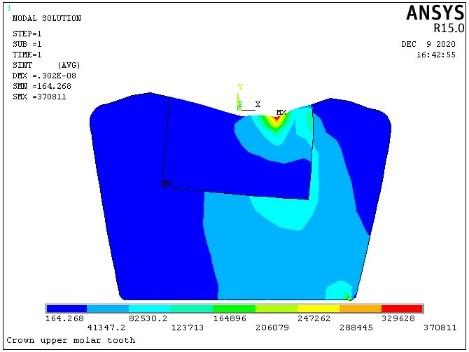
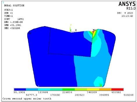
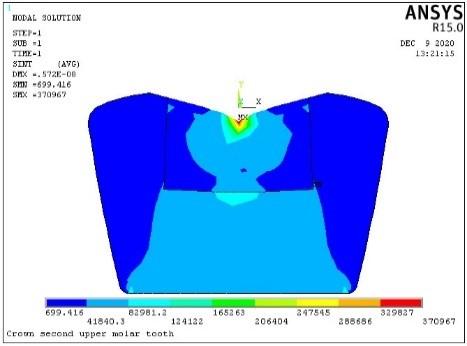
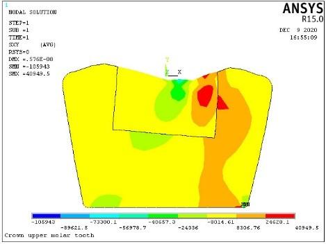
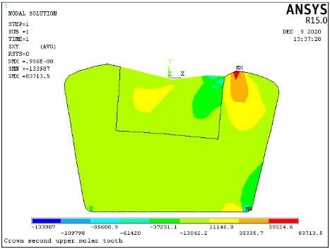
Figures 2, 3, 4, 5 and Table 2 show the results of the deformation tests in mathematical models.
From the Figures 2, 3, 4, 5 and Table 2, we note that the maximum deformation in teeth that have fillings was in the fourth model, the component in its composition is a ceramic filler and at the force exerted on the contact area between the enamel filler and the tooth crown second molar (F3) and its value (9.56 µmm), while the minimum deformation was in the second model, which is present in its zirconium filling composition and at the exerting force in the middle of the filling (F1) and its value (2.62 µmm).
A.
B.
C.
Figure 2. Results of test first model (Enamel) by using ANSYS -15.0 program, Deformation when applying: A. First force, B. Second force, C. Third force
A.
B.
C.
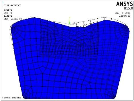
Figure 3. Results of test second model (Zircon) by using ANSYS -15.0 program, Deformation when applying: A. First force, B. Second force, C. Third force
A.
B.
C.
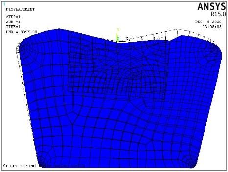
Figure 4. Results of test third model (Titanium) by using ANSYS -15.0 program, Deformation when applying: A. First force, B. Second force, C. Third force
A.
B.
C.
Figure 5. Results of test fourth model (Ceramic) by using ANSYS -15.0 program, Deformation when applying: A. First force, B. Second force, C. Third force
Table 2. The results of the deformation in the fourth models and the force applied on each model, by using ANSYS -15.0 program
|
NO. |
Model |
Material Filling |
Deformation |
||
|
First Force, F1 µmm |
Second Force, F2 µmm |
Third Force, F3 µmm |
|||
|
1 |
M1 |
Enamel |
11.3 |
12.1 |
14.0 |
|
2 |
M2 |
Zirconia |
2.62 |
3.02 |
4.33 |
|
3 |
M3 |
Titanium |
4.97 |
5.76 |
8.39 |
|
4 |
M4 |
Ceramic |
5.72 |
6.66 |
9.56 |
A.
B.
C.
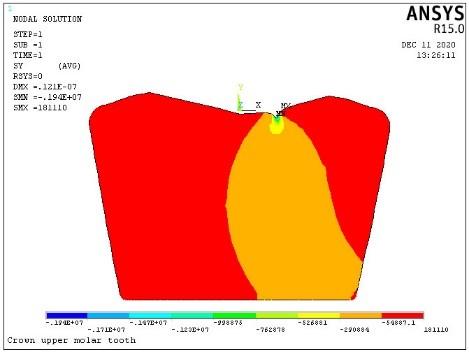
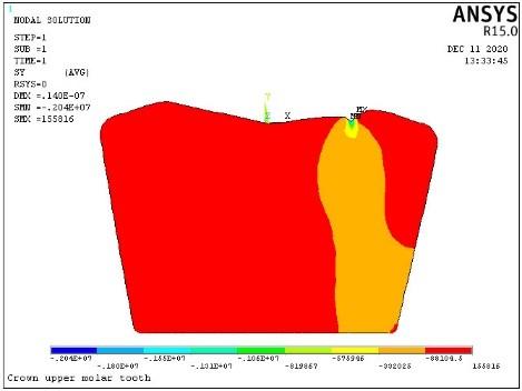
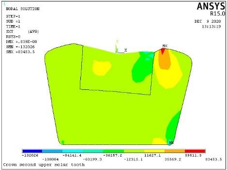
Figure 6. Results of test first model (Enamel) by using ANSYS -15.0 program, normal stress (δy) when applying, A. First force, B. Second force, C. Third force
A.
B.
C.
Figure 7. Results of test second model (Zircon) by using ANSYS -15.0 program, normal stress (δy) when applying, A. First force, B. Second force, C. Third force
A.
B.
C.
Figure 8. Results of test third model (Titanium) by using ANSYS -15.0 program, normal stress (δy) when applying, A. First force, B. Second force, C. Third force
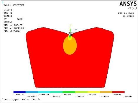
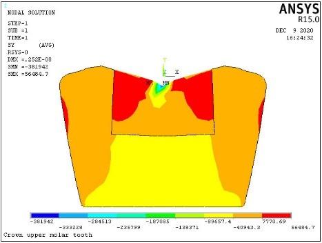
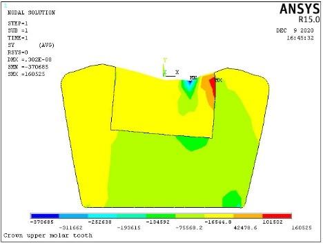
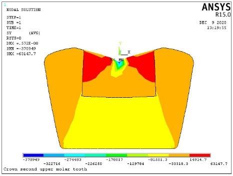
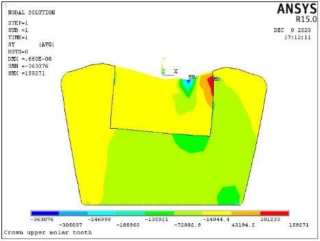
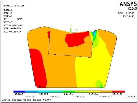
Figures 6, 7, 8, 9 and Table 3 show the results of the normal stress (δy) tests in mathematical models.
From the Figures 6, 7, 8, 9 and Table 3, we note that the maximum normal stress (δy) was in the third model, the component in its composition is a titanium filler and at the force applied on between the middle and end of the filling (F2) and its value (160.8 KPa), while the minimum normal stress (δy) was in the first model, which is present in its ceramic filling composition and at the exerting force in the middle of the filling (F2) and its value (-363.1 KPa).
A.
B.
C.
Figure 9. Results of test fourth model (Ceramic) by using ANSYS -15.0 program, normal stress (δy) when applying, A. First force, B. Second force, C. Third force
Table 3. It shows the results of the normal (δy) in the three models and the force applied on each model, by using ANSYS -15.0 program
|
NO. |
Model |
Material Filling |
Normal Stress (δy) |
|||||
|
First Force, F1 KPa |
Second Force, F2 KPa |
Third Force, F3 KPa |
||||||
|
Minimum Stress (SMN) |
Maximum Stress (SMX) |
SMN |
SMX |
SMN |
SMX |
|||
|
1 |
M1 |
Enamel |
-1880 |
120.4 |
-1940 |
181.1 |
-2040 |
155.8 |
|
2 |
M2 |
Zirconia |
-381.9 |
56.5 |
-370.7 |
160.5 |
-488.7 |
75.8 |
|
3 |
M3 |
Titanium |
-380.7 |
66.4 |
-372.9 |
160.8 |
-507.9 |
71.1 |
|
4 |
M4 |
Ceramic |
-370.9 |
63.1 |
-363.1 |
159.3 |
-496.5 |
71.3 |
A.
B.
C.
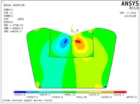
Figure 10. Results of test first model (Enamel) by using ANSYS -15.0 program, Stress intensity (δi) when applying: A. First force, B. Second force, C. Third force
A.
B.
C.
Figure 11. Results of test second model (Zircona) by using ANSYS -15.0 program, Stress intensity (δi) when applying: A. First force, B. Second force, C. Third force
Figures 10, 11, 12, 13 and Table 4 show the test results for the stress intensity distribution of the models.
From the Figures 10, 11, 12, 13 and Table 4, we note that the maximum stress intensity (δi) was in the third model, the component in its composition is a titanium filler and at the force (F3) and its value (510.27 KPa), while the minimum stress intensity (δi) was in the second model, which is present in its zirconium filling composition and at the exerting force (F3) and its value (0.06 KPa).
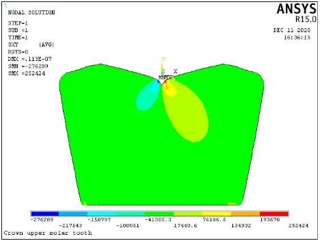
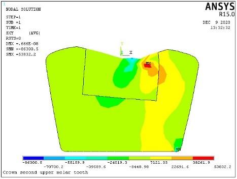
Figures 14, 15, 16, 17 and Table 5 show the test results for the shear stress (τxy) distribution of the models.
A.
B.
C.
Figure 12. Results of test third model (Titanium) by using ANSYS -15.0 program, Stress intensity (δi) when applying: A. First force, B. Second force, C. Third force
A.
B.
C.
Figure 13. Results of test fourth model (Ceramic) by using ANSYS -15.0 program, Stress intensity (δi) when applying: A. First force, B. Second force, C. Third force
Table 4. It shows the results of the Stress intensity (δi) in the fourth models and the force applied on each model, by using ANSYS -15.0 program
|
NO. |
Model |
Material Filling |
Stress Intensity (δi) |
|||||
|
First Force, F1 KPa |
Second Force, F2 KPa |
Third Force, F3 KPa |
||||||
|
Maximum Stress (SMN) |
Minimum Stress (SMX) |
SMN |
SMX |
SMN |
SMX |
|||
|
1 |
M1 |
Enamel |
1.05 |
1880 |
0.34 |
1940 |
0.03 |
2040 |
|
2 |
M2 |
Zirconia |
0.60 |
383.25 |
0.16 |
370.81 |
0.06 |
491.385 |
|
3 |
M3 |
Titanium |
0.61 |
380.71 |
0.16 |
372.41 |
0.09 |
510.27 |
|
4 |
M4 |
Ceramic |
0.70 |
370.97 |
0.17 |
387.64 |
0.78 |
498.87 |
A.
B.
C.
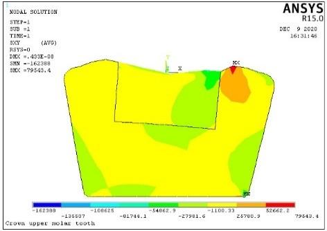
Figure 14. Results of test first model (Enamel) by using ANSYS -15.0 program, shear stress (τxy) when applying: A. First force, B. Second force, C. Third force
A.
B.
C.
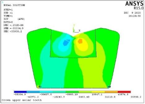
Figure 15. Results of test second model (Zircona) by using ANSYS -15.0 program, shear stress (τxy) when applying: A. First force, B. Second force, C. Third force
A.
B.
C.
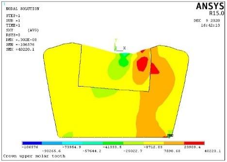
Figure 16. Results of test third model (Titanium) by using ANSYS -15.0 program, shear stress (τxy) when applying: A. First force, B. Second force, C. Third force
A.
B.
C.
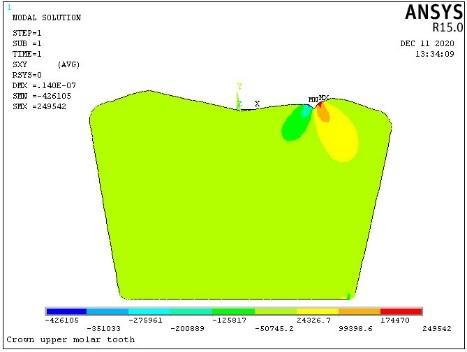
Figure 17. Results of test fourth model (Ceramic) by using ANSYS -15.0 program, shear stress (τxy) when applying,:A. First force, B. Second force, C. Third force
Table 5. It shows the results of the shear stress (τxy) in the fourth models and the force applied on each model, by using ANSYS -15.0 program
|
NO. |
Model |
Material Filling |
shear Stress (τxy) |
|||||
|
First Force, F1 KPa |
Second Force, F2 KPa |
Third Force, F3 KPa |
||||||
|
Maximum Stress (SMN) |
Minimum Stress (SMX) |
SMN |
SMX |
SMN |
SMX |
|||
|
1 |
M1 |
Enamel |
-276.29 |
252.42 |
-438.32 |
239.76 |
-426.11 |
249.54 |
|
2 |
M2 |
Zirconia |
-55.33 |
55.94 |
-106.58 |
40.22 |
-160.39 |
79.54 |
|
3 |
M3 |
Titanium |
-42.43 |
40.01 |
-105.94 |
40.95 |
-132.03 |
83.5 |
|
4 |
M4 |
Ceramic |
-43.26 |
40.58 |
-86.30 |
53.83 |
-133.99 |
83.71 |
From the Figures 14, 15, 16, 17 and Table 5, we note that the maximum shear stress (τxy) was in the third model, the component in its composition is a ceramic filler and at the force (F3) and its value (83.71 KPa), while the minimum shear stress (τxy) was in the first model, which is present in its titanium filling composition and at the exerting force (F1) and its value (- 42.43 KPa).
One of the most important conclusions of this study is that cases of deformation and the distribution of stresses and strains in all parts of the tooth crown were identified with different fillings. The results showed that the least deformation was in the tooth that contains a zircon filler, and its value was (2.62 μmm) when a force was applied in the middle of the filling fixed on the tooth crown (F1), and if it was compared to the deformation of a normal tooth, its resistance to deformation was much higher (99.82%). The highest deformation in the models with fillings was in the tooth containing the ceramic filler and when a vertical force was applied in the area of contact of the tooth with the filling (F2), and when compared to the resistance to deformation of a normal tooth, its resistance is slightly better (31.62%). Another conclusion is that the state of different stresses and strains of the mathematical model of the tooth that contains zircon filling is much better than the cases of different stresses and strains in a normal tooth, and this may be bad for preserving the tooth when the tooth is exposed to a high vertical force in the area of contact of the tooth with the filling, because that It may lead to the breakage of the tooth in the contact area with the zircon filling (i.e. the lack of a fit in terms of the endurance value because there is a large difference between the resistance of zircon and the resistance of the natural tooth), but the results showed that the tooth that contains the ceramic filling is in a suitable fit with the natural tooth in terms of bearing different stresses and strains, hence we can say ceramic fillings are better than zircon or titanium in terms of deformation and resistance to various stresses and strains.
The other conclusion is that the lowest stress intensity (δi) in the mathematical model of normal tooth is very little compared to the models that contain different fillings, while the highest tress intensity (δi) in the mathematical models containing fillings (Zirconia, Titanium, Ceramic) is less than (75%) the highest tress intensity (δi) in normal teeth.
Future proposals for this subject should concentrate on the practical side, the use of these materials, the creation of models from these materials, and the comparison of practical and theoretical outcomes, as this is how high-quality materials with high strength and resistance to loads are produced.
The Ministry of Higher Education and Scientific Research of the Republic of Iraq funded the Engineering Science Research Program through the Northern Technical University/Technical Institute of Mosul and the Hamdaniya University plan in medical physics and dentistry (No. 1333- 2020).
[1] Li, W.Y., Sun, J. (2018). Effects of ceramic density and sintering temperature on the mechanical properties of a novel polymer-infiltrated ceramic-network zirconia dental restorative (filling) material. Medical Science Monitor, 24: 3068-3076. https://doi.org/10.12659/MSM.907097
[2] ISO I. 6872: Dentistry-ceramic materials. Switzerland: International Organization for Standardization (IOS). 2008.
[3] Chun, K.J., Lee, J.Y. (2014). Comparative study of mechanical properties of dental restorative materials and dental hard tissues in compressive loads. Journal of Dental Biomechanics, 5: 1-6. https://doi.org/10.1177/1758736014555246
[4] Muslov, S.A. (2018). Anisotropy of poisson's ratio of dentin and enamel. Materials Science and Engineering, 441: 1-9. https://doi.org/10.1088/1757-899X/441/1/012032
[5] Davies, R.A., Ardalan, S., Mu, W.H., Tian, K., Farsaikiya, F., Darvell, B.W., Chass, G.A. (2010). Geometric, electronic and elastic properties of dental silver amalgam g-(Ag3Sn), g1-(Ag2Hg3), g2-(Sn8Hg) phases, comparison of experiment and theory. Intermetallics, 18: 756-760. https://doi.org/10.1016/j.intermet.2009.12.004
[6] Prados-Privado, M., Martínez-Martínez, C., Gehrke, S.A., Prados-Frutos, J.C. (2020). Influence of bone definition and finite element parameters in bone and dental implants stress: A literature review. Biology, 9(8): 224. https://doi.org/10.3390/biology9080224
[7] Spreafico, R.C., Krejci, I., Dietschi, D. (2005). Clinical performance and marginal adaptation of class II direct and semidirect composite restorations over 3.5 years in vivo. Journal of Dentistry, 33(6): 499-507. https://doi.org/10.1016/j.jdent.2004.11.009
[8] Toparli, M., Gökay, N., Aksoy, T. (2000). An investigation of temperature and stress distribution on a restored maxillary second premolar tooth using a three-dimensional finite element method. Journal of Oral Rehabilitation, 27(12): 1077-1081. https://doi.org/10.1111/j.1365-2842.2000.00633.x
[9] Toparli, M., Aykul, H., Sasaki, S. (2003). Temperature and thermal stress analysis of a crowned maxillary second premolar tooth using three-dimensional finite element method. Journal of Oral Rehabilitation, 30(1): 99-105. https://doi.org/10.1046/j.1365-2842.2003.00971.x
[10] Cornacchia, T.P.M., Las Casas, E.B., Cimini, C.A., Peixoto, R.G. (2010). 3D finite element analysis on esthetic indirect dental restorations under thermal and mechanical loading. Medical & Biological Engineering & Computing, 48: 1107-1113. https://doi.org/10.1007/s11517-010-0661-7
[11] Padgelwar, A.G. (2016). Stress analysis of human tooth using Ansys. International Journal of Engineering Science and Computing, 6(4): 4379-4384.
[12] Imanishi, A., Nakamura, T., Ohyama, T., Nakamura, T. (2003). 3-D finite element analysis of all-ceramic posterior crowns. Journal of Oral Rehabilitation, 30(8): 818-822. https://doi.org/10.1046/j.1365-2842.2003.01123.x
[13] Proos, K.A., Swain, M.V., Ironside, J., Steven, G.P. (2002). Finite element analysis studies of an all-ceramic crown on a first premolar. International Journal of Prosthodontics, 15(4): 404-412.
[14] Proos, K.A., Swain, M.V., Ironside, J., Steven, G.P. (2002). Finite element analysis studies of a metal-ceramic crown on a first premolar tooth. International Journal of Prosthodontics, 15(6): 521-527.
[15] Nakamura T, Imanishi A, Kashima H, Ohyama T, Ishigaki S. (2001). Stress analysis of metal-free polymer crowns using the three-dimensional finite element method. International Journal of Prosthodontics, 14(5): 401-405.
[16] D'souza, K.M., Aras, M.A. (2017). Three-dimensional finite element analysis of the stress distribution pattern in a mandibular first molar tooth restored with five different restorative materials. Journal of Indian Prosthodontic Society, 17(1): 53-60. https://doi.org/10.4103/0972-4052.197938
[17] Kumar, P., Rao, R.N. (2015). Three-dimensional finite element analysis of stress distribution in a tooth restored with metal and fiber posts of varying diameters: An in-vitro study. Journal of Conservative Dentistry, 18(2): 100-104. https://doi.org/10.4103/0972-0707.153061
[18] Li, L.L., Wang, Z.Y., Bai, Z.C., Mao, Y., Gao, B., Xin, H.T., Zhou, B., Zhang, Y., Liu, B. (2006). Three-dimensional finite element analysis of weakened roots restored with different cements in combination with titanium alloy posts. Chinese Medical Journal, 119(4): pp. 305-311.
[19] Heo, K.H., Lim, Y.J., Kim, M.J., Kwon, H.B. (2018). Three-dimensional finite element analysis of the splinted implant prosthesis in a reconstructed mandible. The Journal of Advanced Prosthodontics, 10(2): 138-146. https://doi.org/10.4047/jap.2018.10.2.138
[20] Yang, H., Park, C., Shin, J.H., Yun, K.D., Lim, H.P., Park, S.W., Chung, H. (2018). Stress distribution in premolars restored with inlays or onlays: 3D finite element analysis. Journal Advanced Prosthodontics, 10(3): 184-190. https://doi.org/10.4047/jap.2018.10.3.184
[21] Karash, E.T., Alsttar Sediqer, T.A., Elias Kassim, M.T. (2021). A comparison between a solid block made of concrete and others made of different composite materials. Revue des Composites et des Matériaux Avancés, 31(6): 341-347. https://doi.org/10.18280/RCMA.310605
[22] Najim, M., Sultan, J., Karash, E. (2020). Comparison of the resistance of soild shell of composite materials with other soild metal Materials. In: IMDC-SDSP 2020, pp. 28-30. https://doi.org/10.4108/eai.28-6-2020.2298518
[23] Karash, E.T. (2011). Modelling of unilateral contact of metal and fiberglass shells. In Applied Mechanics and Materials, 87: 206-208. https://doi.org/10.4028/www.scientific.net/AMM.87.20
[24] Karash, E.T. (2017). The study contacts bending stress two-layer plates from fiberglass with interfacial defects of structure. Agricultural Research & Technology, 12(1): 1-4. https://doi.org/10.19080/ARTOAJ.2017.12.555834
[25] Karash, E.T. (2016). Experimental and theoretical results of the internal hydro static pres-sure of multilateral pipes. Materials Science MSAIJ, an Indian Journal, 14(8): 316-325.
[26] Vershchaka, S.M., Karash, E.T. (2012). Modeling of multi-layer composite material pipes under internal pressure. International Journal of Structronics & Mechatronics, 1-12.
[27] Najem, M.K., Karash, E.T., Sultan, J.N. (2022). The amount of excess weight from the design of an armored vehicle body by using composite materials instead of steel. Revue des Composites et des Matériaux Avancés-Journal of Composite and Advanced Materials, 32(1): 1-10. https://doi.org/10.18280/rcma.320101
[28] Karash, E.T., Sultan, J.N., Najem, M.K. (2022). The difference in the wall thickness of the helicopter structure are made of composite materials with another made of steel. Mathematical Modelling of Engineering Problems, 9(2): 313-324. https://doi.org/10.18280/mmep.090204