OPEN ACCESS
This paper is the second part of a comprehensive 3D CFD work on compound parabolic collectors (CPC) to identify the operation details of nanoparticles in the middle fluid inside the main pipe (solar collector). In the first part, the effect of time on the heat transfer and efficiency of the solar collector was reported. As the result of the first section of this study, the maximum heat transfer and efficiency can be achieved at 12 O'clock. The second part deals with how the system works with different types and volume fractions (0, 2, 4, 6, 8 and 10%) of nano particles. So, two different nano particles are considered as TiO2 and Al2O3. The results show that Al2O3 is recommended compared to TiO2, because Al2O3 can provide the better Nusselt number compared to TiO2. Furthermore, there is a same optimum volume fraction for both nanoparticles equal to 8%.
compound parabolic collectors (CPC), volume fraction, nano particles type, solar efficiency
Today the importance of solar energy usage is proven. The modern industrial communities are moving towards the use of clean and cheap energies like solar energy. The widespread use of old energy sources (like fossil energy) has led to severe climate changes in some parts of the planet and this matter is obvious that this process will make the planet uninhabitable. This matter shows the importance of developments and researches on the solar devices. The first part of this study focused on using of Al2O3 as the nano particle in the solar system. The kind of nanoparticles can be so effective and important in thermal efficiency of solar systems, so, a comparison between Al2O3 and TiO2 is performed to clarify the effect of nanoparticle type. This comparison is managed in different volume fractions between 0 to 10%. In the following, some important works on solar devices equipped with nanotechnologies are summarized. Muraleedharan et al. [1] analyzed the optical and thermal characteristics of Al2O3-Therminol®55 nano heat transfer fluid (nHTF 0.25 to 0.3%) in a solar collector. They reported that 0.1% is the best volume fraction for Al2O3 which elevates the heat transfer characteristics of nano fluid in solar system around 11.7%. Zheng et al. [2] combined two different solar collectors (compound parabolic concentrator and flat solar collectors) and introduced it as a new kind of solar collector with higher efficiency. Bellos et al. [3] inserted an evacuated tube on a compound parabolic collector to improve the thermal performance of this system. They optimized the reflector geometry and the effect of solar angle is analyzed. Su et al. [4] presented a numerical domain for a compound parabolic collector using a ray tracing model. Sainath and Gulhane [5] evaluated and optimized the receiver position and the CPC performance using minimization of the optical loses.
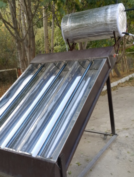
The simulated model is a 3D model created based on a real solar collector (Figure 1).
Figure 1. Real case of compound parabolic collector (CPC) which is modeled in the simulations
The real model contains three solar collectors with three parabolic reflectors. The inlet water enters the system via the middle pipe and is warming in three different cycles (for each collector). One collector is chosen to be modeled as the main numerical domain with defined diameters (explained in part Ӏ). The mesh shapes and their organization are very important to reach the reliable and correct results from a numerical model, so, a model with more structured domain can present the better results. The created model in this study follows the mentioned pattern and utilizes the organized meshing method (As explained in part Ӏ).
The governing equations for the three-dimensional and laminar flow are written as:
Continuity equation
$\frac{\partial u}{\partial x}+\frac{\partial v}{\partial y}+\frac{\partial w}{\partial z}=0$ (1)
Momentum equation
$\rho_{n f}\left(u \frac{\partial u}{\partial x}+v \frac{\partial u}{\partial y}+w \frac{\partial u}{\partial z}\right)=-\frac{\partial p}{\partial x}+\mu_{n f}\left(\frac{\partial^{2} u}{\partial x^{2}}+\frac{\partial^{2} u}{\partial y^{2}}+\frac{\partial^{2} u}{\partial z^{2}}\right)$ (2)
$\rho_{n f}\left(u \frac{\partial v}{\partial x}+v \frac{\partial v}{\partial y}+w \frac{\partial v}{\partial z}\right)$$=-\frac{\partial p}{\partial y}+\mu_{n f}\left(\frac{\partial^{2} v}{\partial x^{2}}+\frac{\partial^{2} v}{\partial y^{2}}+\frac{\partial^{2} v}{\partial z^{2}}\right)$$+\rho_{n f} \beta_{n f}\left(T-\mathrm{T}_{r e f}\right)$ (3)
$\rho_{n f}\left(u \frac{\partial w}{\partial x}+v \frac{\partial w}{\partial y}+w \frac{\partial w}{\partial z}\right)=-\frac{\partial p}{\partial z}+\mu_{n f}\left(\frac{\partial^{2} w}{\partial x^{2}}+\frac{\partial^{2} w}{\partial y^{2}}+\frac{\partial^{2} w}{\partial z^{2}}\right)$ (4)
Energy equation
$\left(\rho c_{p}\right)_{n f}\left(u \frac{\partial T}{\partial x}+v \frac{\partial T}{\partial y}+w \frac{\partial T}{\partial z}\right)=K_{n f}\left(\frac{\partial^{2} T}{\partial x^{2}}+\frac{\partial^{2} T}{\partial y^{2}}+\frac{\partial^{2} T}{\partial z^{2}}\right)$ (5)
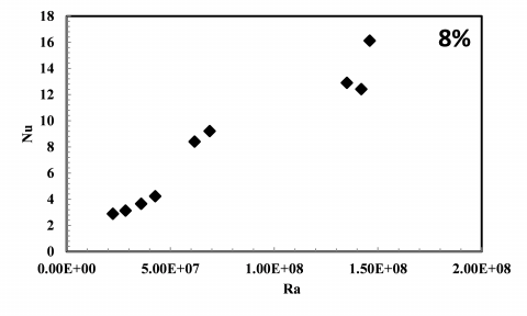
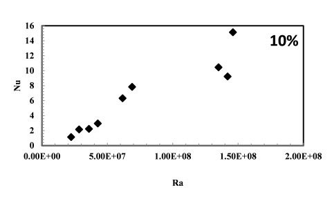
Figure 2 shows the Nusselt number changes relative to Rayleigh number variations for the water pipes inside the collector. As seen in Fig. 2, when the Ra number increases, the Nusselt number will be improved for all volume fractions (2, 4and 10%). The improvements of free motions around the pipes have very important roles in this elevation in heat transfer processes.
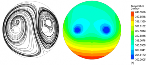
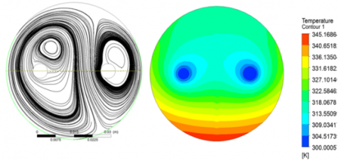
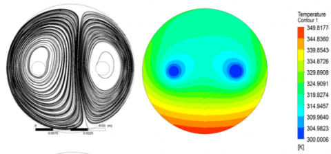
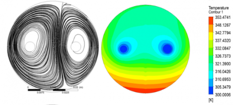
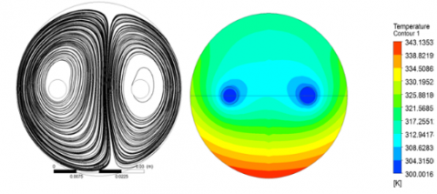
The exact geometry of the solar collector is explained and plotted in Part Ӏ, so, according to the mentioned geometry, the related angles for the upper wall (the direct receiver) and the bottom wall (the indirect wall) are equal to 120 and 240 degrees, respectively. It can be observable that the reflected ray (which is inserted on the bottom wall) is bigger than the direct radiation flux on the upper wall. The main factor of heat transfer process in the main domain of the mentioned CPC is the free motion of the water or the nano fluid layers around the middle pipes inside the collector. So, the main point in this study is improvement of the vortexes around the cold and hot water using nano particles. Different volume fractions are examined including 0 (pure water), 2, 4, 6, 8, 10 % for both Al2O3 and TiO2. Figure 3 and 4 show the temperature separation profiles for both Al2O3 and TiO2 including different volume fractions.
As said before, Figure 3 and 4 indicate the difference between heat transfer process regarding TiO2 and Al2O3. As seen in these contours and streamlines, the vortexes in the case of Al2O3 are more developed compared to the solar system operating with TiO2. So, this is expectable that the heating efficiency of the CPC solar system operating with Al2O3 is higher than the CPC with TiO2 nano particle. Another interesting thing observed from the contours is the higher temperature of the bottom wall of the collector compared to other regions. This matter confirms that the parabolic plates can collect the solar rays and increase the thermal effects on the collectors, extremely. The contours have been prepared at Ra=1.46×10⁸.
(a)
(b)
(c)
Figure 2. Nusselt number changes as a function of Ra number for different volume fractions
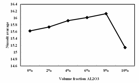
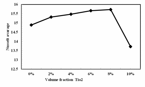
When the nano particle's fraction increases, the vertical component of velocity increases, and the horizontal item decreases, so, the free convection effect improves. This effect is observable in the fraction range of 0 to 8%. After that, the free convection effect decreases and the heating effectiveness drops. In fact, the random motion of the particles (nano particles) or the Brownian motion increases the heat transfer between the walls and the middle fluid. Fig. 5 shows the temperature differences including the temperature difference between the head and bottom of the inlet line $\Delta T_{1}=T_{A^{\prime}}-T_{A}$, the temperature difference between the head and bottom of the outlet line $\Delta T_{2}=T_{B^{\prime}}-T_{B}$
and the total temperature difference (between head of inlet line and bottom of the outlet line) $\Delta T_{t}=T_{B}-T_{A}$ as a function of the nano particle's volume fraction. The temperature differences (for all cases) improve during the fraction axis upto 8%. When the volume fraction increases to the larger values (more than 8%) the temperature differences decrease. So, it can be concluded that the volume fraction of 8% is the best option for both nanoparticles.
|
Volume fraction (%) |
Streamlines |
Temperature contour |
|
0 |
||
|
2 |
||
|
4 |
||
|
6 |
||
|
8 |
||
|
10 |
||
Figure 3. Temperature contours and streamlines ofr different volume fractions of TiO2
(a)
(b)
Figure 4. Variation of Nusselt number as a function of volume fraction
The present investigation is the second part of a comprehensive 3D CFD work on compound parabolic collectors (CPC) to identify the operation details of nanoparticles in the middle fluid inside the main pipe (solar collector). As the result of the first section of this study, the maximum heat transfer and efficiency can be achieved at 12 O'clock. The second part deals with how the system works with different types and volume fractions (0, 2, 4, 6, 8 and 10) of nano particles. So, two different nano particles are considered as TiO2 and Al2O3. As the results, when the Ra number increases, the Nusselt number will be improved for all volume fractions (2, 4 and 10%). The improvements of free motions around the pipes have very important roles in this elevation (in heat transfer processes). According to the results, the vortexes in the case of Al2O3 are more developed compared to the solar system operating with TiO2. So, this is expectable that the heating efficiency of the CPC solar system operating with Al2O3 is higher than the CPC with TiO2 nano particle. Another interesting thing observed from the contours is the higher temperature of the bottom wall of the collector. This matter confirms that the parabolic plates can collect the solar rays and increase the thermal effects on the collectors, extremely.
Ec Eckert number, $\mu_{f} \alpha_{f} k /\left[\left(\rho c_{p}\right)_{f} q^{\prime \prime} L^{3}\right]$
$C_{p}$ specific heat at constant pressure
Gr Grashof number
$N U_{l o}$ local Nusselt number
$N U_{a v e}$ average Nusselt number
Pr Prandtl number, $\vartheta_{f} / \alpha_{f}$
T fluid temperature
u,v,w velocity component in the x-direction and y-direction and z-direction
X,Y,Z dimensionless space coordinates
U,V,W c
K thermal conductivity
Ra Rayleigh Number $\left(=g \beta_{f} q^{\prime \prime} L^{4} / k \alpha_{f} \vartheta_{f}\right)$
Greek symbols
$\alpha$ thermal diffusivity
$\vartheta$ kinematic viscosity
$\emptyset$ volume fraction
$\mu$ dynamic viscosity
$\theta$ dimensionless temperature
$\rho$ fluid density
$\beta$ thermal expansion coefficient
Subscripts
c cold
h hot
nf nanofluid
f base fluid
n nanoparticle
in inlet
out outlet
[1] Muraleedharan M, Singh H, Suresh S, Udayakumar M. (2016). Directly absorbing Therminol-Al2O3 nano heat transfer fluid for linear solar concentrating collectors. Solar Energy 137: 134–142.
[2] Zheng W, Yang L, Zhang H, You S, Zhu C. (2016). Numerical and experimental investigation on a new type of compound parabolic concentrator solar collector. Energy Conversion and Management 129:11–22.
[3] Bellos E, Korres D, Tzivanidis C, Antonopoulos KA. (2016). Design, simulation and optimization of a compound parabolic collector. Sustainable Energy Technologies and Assessments 16: 53–63.
[4] Su ZY, Gu SY, Vafai K. (2017). Modeling and simulation of ray tracing for compound parabolic thermal solar collector. International Communications in Heat and Mass Transfer 87: 169-174.
[5] Waghmare SA, Gulhane NP. (2017). Optical evaluation of compound parabolic collector with low acceptance angle. Optik - International Journal for Light and Electron Optics 149: 359-371.