Shahram Fallah Faal | Alireza Sahab* | Behnam Alizadeh
© 2023 IIETA. This article is published by IIETA and is licensed under the CC BY 4.0 license (http://creativecommons.org/licenses/by/4.0/).
OPEN ACCESS
With increasing the penetration rate of microgrids in power networks, their control becomes more and more important, and microgrid frequency control in islanded mode is one of the most important recent approaches which are studied. With the aim of fast microgrid frequency adjustment, this study presents a novel robust approach using fuzzy and reset techniques. Therefore, this paper firstly describes the model of an islanded microgrid consisting of various elements such as renewable resources, variable loads, storage resources and distributed energy resources, and then designs and presents a robust hybrid control technique based on switching. The planned control method consists of three parts, which are: 1- Fuzzy control technique, 2- Fuzzy reset control technique, and 3- Switching between the two techniques. Due to the robust feature of the reset technique, which in addition to quickly reducing the frequency error, it is able to overcome the limitations of linear controllers, and also due to the intelligence of the innovative fuzzy technique, the planned technique is able to quickly remove frequency errors and restore the islanded microgrid frequency in the fastest possible time and with the least ups and downs and fluctuations. As the results of simulation and comparison in MATLAB environment show, the planned technique has a high and undeniable ability to overcome the uncertainty of the model and disturbances on the system even of the most severe type.
microgrid, islanded microgrid, frequency control, robust method, fuzzy method, reset method, hybrid method, hybrid control, uncertainty, disturbance, frequency error
As a very positive and constructive structure, the microgrid plays a very important role in redesigning and optimizing the production and consumption of electric power today. The numerous advantages of microgrids have caused increasing attention to this concept and structure, and this process has caused a re-arrangement in the production structure and of course the distribution of electric power [1]. The ability to aggregate and integrate renewable resources with microgridbased networks has reduced greenhouse gas production and thus condensed pollution [2]. The capability to produce energy on-site with the consumer has led to the reduction of transmission losses and the elimination of sufferers caused by centralized production, the skill to manage production and consumption in the microgrid structure has reduced investment costs to provide suitable power for new plants, and of course, decreasing power prices and reducing peak power requirements, the skill to work independently or connected to the main macrogrid network, increasing reliability and the ability to deal with cyber-attacks are among the main advantages of microgrid networks [3]. For this purpose, the microgrid networks are the place of many studies in this field.
Among the various features of the microgrid structure, the use of renewable resources and distributed generation resources is a special potential for the development of this concept [4]. Because it provides more secure energy penetration in remote areas and it provides the possibility of integration by reducing costs and increasing energy efficiency [5]. These unique features and specifications further explain the need to face and overcome the problems facing the concept of microgrid structure, the most important of which are in the fields of stability, two-way power flows, modeling and control [6]. Designing and presenting appropriate methods in facing these challenges forms the study path of many researchers and for this reason, the design of the appropriate control method for the microgrid frequency regulation has been considered in this study despite the low inertia, the presence of uncertainty, and disturbances in both load and generation.
Frequency characteristic along with voltage specification are the most important parameters of an electric power system and in this study, frequency control of the microgrid network in the islanded mode is targeted. Frequency control is necessary and vital for the correct operation of the power network. Any frequency deviation outside the permitted limits leads to inconsistency between production parts and downstream equipment, which in the first place causes damage to these components and ultimately causes instability and collapse of the network. Many control studies have been done to adjust the frequency of different microgrids, especially in the islanded mode, among which the following can be mentioned: The proportional integral (PI) control method in [7-9], Ziegler-Nichols based method for adjusting proportional integral derivative (PID) controller parameters in [10], H∞ controller to minimize fluctuations in [11], internal model controller in [12] swarm-based techniques [13], genetic algorithms [14] and biography optimization techniques [15] have been used to control the frequency of microgrid.
Despite the fact that low inertia in microgrid networks due to the presence of elements with slow dynamics slows down frequency deviations, but this low inertia acts as a negative factor for microgrid frequency control when deviations occur and is an undesirable element for frequency regulation. Disturbances in generation as well as consumption are among the undesirable components for frequency control [16]. Changes and disturbances in the net and total generation of DER in the microgrid network cause deviations in the frequency of the microgrid, and when these changes are combined with load disturbances caused by consumer behavior, the most intense shocks occur in the frequency of the microgrid where a proper and timely response from the controller is necessary in these moments [17]. The existence of uncertainty, which is obvious in the modeling of the dynamics of the various elements existing in the microgrid network, causes the frequency controller design problem to burst more and more. In addition to the mentioned issues, the response resulting from the controller's actions must show a suitable quality from the perspective of transient and permanent characteristics. This study presents a new control approach for microgrid frequency regulation considering all the mentioned considerations.
As mentioned, despite the various control methods implemented for microgrid systems, the development and completion of new control approaches is necessary and essential. Some of the presented methods are unable to handle the nonlinear effects of microgrid system dynamics due to the linear nature of the controllers [18-19]. Some of them do not have tolerance and robustness against possible adversities such as model uncertainty and disturbances and also, some others cannot be implemented and operationalized due to their complex nature. Therefore, it is necessary to develop and design new innovative approaches. With this point of view and taking into account the unique capabilities and characteristics of the reset and fuzzy techniques [20-21], this paper presents a new technique for microgrid frequency control and regulation and of course, evaluates the robustness of the controller under the most extreme possible scenarios caused by uncertainty and disturbance. Fuzzy technique as an intelligent method is closely related to human logic and thinking and can be added to existing power systems in a quick and low-cost way, and in addition, it is one of the most important tools in dealing with uncertain and complex systems [22]. Due to the use of two integrators in a unique non-linear structure, the reset technique is able to quickly remove the tracking error and perform regulation in addition to overcoming the limitations of linear controllers and in addition, transient response improvement is one of the unique features of the control method. Another innovation of this study, in addition to using these two methods, is the combination of the mentioned two approaches and switching between control techniques. The fuzzy method by determining suitable rules derived from experience is one of the control solutions designed in this study, and the other planned technique is based on the reset technique, of course, its gains are determined by designing and using fuzzy rules. Switching between the two mentioned approaches under certain conditions is another innovation of this study for optimal frequency control, and in fact, the designed switching enables the use of the best option among fuzzy and optimized fuzzy reset controllers.
Accordingly, this article is organized as follows: in the second part, the microgrid model is presented. The third part describes each of the control methods and how they are placed in the proposed comprehensive control technique. The fourth section describes the results of the implementation and application of the controller to the islanded microgrid in different scenarios, and finally, the obtained results have been evaluated and analyzed in the fifth part, and of course, the direction of future studies has also been drawn.
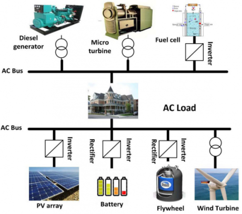
In this study, the microgrid is considered in island mode and AC type, and various elements such as ac loads, distributed generation including fuel cell, micro turbine, wind turbine, solar cell and energy storage devices such as FES and BES systems are located in this structure. A simple structure of the studied microgrid is shown in Figure 1, in which the distributed sources are connected to the AC bus by the electronic-power tool, and the conversion of DC voltage to AC in sources such as PV and FC arrays is done through this tool. For the BES system, a converter is installed to convert AC to DC in charging mode and DC to AC in discharging mode. The total power generation from DEG, MT, WTG, PV, FC sources and FES and BES exchange power should be able to meet the power demand.
Due to the effect of environmental conditions on the power produced by RES such as PV and WTG, these sources are not used for frequency regulation, and to achieve the secondary control goal, microturine and fuel cell have been used for this purpose. In the secondary frequency control loop, fluctuations in load output power, WTG and PV are compensated by decreasing/increasing output power from MT and FC. Of course, it should be noted that the delay in fuel cell dynamics for power generation is included in this study. In Table 1, the dynamic model with the lowest order is given for each of the elements presented in the microgrid.
Table 1. dynamic model with the lowest order for each of the elements
|
Microgrid Element |
Dynamic Model |
|
Wind Turbine |
|
|
Battery Energy Storage System (BESS) |
|
|
Diesel Engine Generator |
|
|
Solar Power |
|
|
Fuel Cell |
In the following, simplified dynamic models are presented for DGs/storage units. Some distributed sources may have high-order dynamic frequency response models, but according to [19], low-order dynamic models are sufficient to investigate the issue of frequency control. Figure 2 shows a dynamic frequency response model of MG, and the corresponding system parameters for a typical MG are taken from reference [4].
Figure 1. Simplified structure of the studied microgrid
Figure 2. MG frequency response model
This section describes the structure of the proposed controller in detail. In order to meet the control requirements and maintain the microgrid frequency value at the desired value, designing a robust and effective controller is essential. Due to the special capabilities of the reset and fuzzy approaches, these two methodologies have been used effectively for designing the robust intelligent controller. In general, the designed controller structure consists of three basic parts, which will be described below. These three parts include; 1- separate fuzzy control technique, 2- reset robust control technique, tunable by fuzzy scheme, 3- and switching and selector between the controllers. By placing these three sub-controllers in a certain structure, they form the layout of the proposed hybrid controller structure. Now we will describe each of these parts.
3.1 Fuzzy intelligent control (Fuzzy logic)
Fuzzy logic is one of the best control techniques due to its simplicity of design and implementation, high efficiency and robustness against system dynamic changes. Fuzzy logic controller synthesis does not require detailed system information. Figure 3 shows the three main parts in the Fuzzy Logic Controller (FLC). The fuzzification interface maps a crisp input to a fuzzy value using fuzzy sets. The rule set and inference system creates a result for each appropriate rule, then combines the results of the rules. The defuzzification section make over the combined result into a specific control value. For fuzzification and defuzzification interfaces, this control method considers five membership functions that are adjusted according to the error value and accuracy required by the closed-loop system.
Figure 3. Layout of fuzzy controller
In Figure 3 , the variables $e ; \Delta e ; E$ and $\Delta E$ show the error rate, error derivative, normalized error and normalized error derivative, respectively. Parameters $\kappa_1, \kappa_2$ and $a$ are input and output scaling factors and have important effect on the dynamic behavior of the system and can be selected based on experience, by trial and error in simulations, or using advanced meta-heuristic approaches [3]. In Table 2, the fuzzy linguistic variables $\mathrm{NB}, \mathrm{N}, \mathrm{Z}, \mathrm{P}$ and $\mathrm{PB}$ signify large negative, negative, zero, positive and large positive, respectively. The basic form for fuzzy control rules is described as follows: "If the error $E$ is $A$ and the derivative of the error $\Delta E$ is $B$, then the output of the fuzzy control is $\Delta u^{\prime \prime}$. Figures 4(a) and 4(b) show the input and output membership functions of FLC, respectively.
Table 2. The linear basis rules used in FLC
|
$\Delta u$ |
E |
|||||
|
NB |
N |
Z |
P |
PB |
||
|
$\Delta E$ |
NB |
NB |
NB |
N |
N |
Z |
|
N |
NB |
N |
N |
Z |
P |
|
|
Z |
N |
N |
Z |
P |
P |
|
|
P |
N |
Z |
P |
P |
PB |
|
|
PB |
Z |
P |
P |
PB |
PB |
|
(a)
(b)
Figure 4. The membership functions of FLC. (a) input membership functions (b) output membership functions
3.2 Robust reset controller optimized by fuzzy method
In this part, the structure of the reset scheme is described at first, and then the reset approach optimized with the fuzzy technique is explained in the next subsection.
3.2.1 Reset method
Reset control scheme is shown in Figure 5. It is widely used in industrial process control due to its simple structure and robust performance, and is able to quickly eliminate tracking error and improve transient response for both linear and nonlinear systems. In the following, the method of adjusting the reset control coefficients by the fuzzy technique is explained.
Figure 5. layout of reset controller
3.2.2 Reset controller with fuzzy tune
Fixed coefficients for the reset controller in non-linear plants with parameter changes cannot show proper functionality and performance. Therefore, it is necessary to use innovative and automatic approaches for adjusting the parameters of the reset controller. The fuzzy-based self-tuning reset (FSR) controller shown in Figure 6 provides the ability to adjust the coefficients of the reset control method, i.e. $\kappa_p ; \kappa_i$ and $\kappa_d$ by using of a fuzzy tuner [4].
Figure 6. Layout of fuzzy-based self-tuning reset controller
The output of the FSR approach is specified by
$\begin{aligned} u_{F S R}(t)=\kappa_p e(t) & +\kappa_i \int e(t) d t +\kappa_{\text {iReset }} \int_{\text {Reset }} e(t) d t\end{aligned}$ (1)
Figure 7 shows more details about the fuzzy tuner.
Figure 7. Layout of the fuzzy tuner
There are two inputs to the fuzzy inference: $e$ and $\Delta e$, and three outputs: $\kappa_p, \kappa_i$ and $\kappa_{i R e s e t}$ in Figure 7. The variables $e ; \Delta e ; E$ and $\Delta E$ specify the error rate, error derivative, normalized error and normalized error derivative, respectively. The parameters $\kappa_1, \kappa_2, \alpha, \beta$ and $\gamma$ are input/output scaling factors.
Fuzzy subsets for inputs and outputs are negative, zero and positive. Figures 8 (a) and (b) show the membership functions of inputs and outputs, respectively.
(a)
(b)
Figure 8. The membership functions of fuzzy tuner (a) input membership functions (b) output membership functions
As given in Table 3 , the columns signify the normalized feedback error $E$ and the rows denote the normalized derivative of error $\Delta E$. Each pair $[E, \Delta E]$ governs the output parameters matching to $\kappa_p^{\prime}, \kappa_i^{\prime}$ and $\kappa_{\text {iReset }}^{\prime}$.
Table 3. Fuzzy rules for FSR approach
|
$\kappa_p^{\prime}, \kappa_i^{\prime}, \kappa_{i \text { Reset }}^{\prime}$ |
E |
|||
|
N |
Z |
P |
||
|
$\Delta E$ |
N |
ZNN |
ZNN |
PNN |
|
Z |
PZZ |
ZZN |
ZNN |
|
|
P |
PPP |
ZPN |
NPN |
|
In the presented fuzzy tuner, the sum of the product is considered as the inference method, the center of gravity as the defuzzification method, and the triangular-shaped as the membership functions for the inputs and outputs.
3.3 Switching and selective controller between optimized reset and fuzzy techniques
In this part, the structure of a fuzzy-reset controller is presented to improve the dynamic performance and fast adjustment of microgrid frequency. Both fuzzy and reset controllers are presented in this structure, and therefore combining the advantages of the two methods somehow creates an added value. The planned control scheme is shown in Figure 9, which includes three parts:1- Fuzzy-based adjusted reset controller; 2- Fuzzy controller; 3- Fuzzy selector. Based on the fuzzy rules and depending on the error between the current value of the microgrid frequency and its desired value, the fuzzy selector determines the time and how to change the controller in a suitable way. If the output value of the system is far from the set point, the fuzzy controller has the greatest effect on the control system. Similarly, when the output value is close to the set point value, the fuzzy reset controller in turn has the highest effect on the system and this rule shows how to select the controller based on the fuzzy selector.
As Figure 9 shows, the inputs of the fuzzy selector are e, $\Delta e$ and the input fuzzy linguistic variables are $N, Z$ and $P$. The output of the fuzzy selector is the $r_{f u z z y}$ and the fuzzy linguistic variables corresponding to the output are $\mathrm{P}$ and $\mathrm{PB}$. Fuzzy inference rules are given in Table 4.
Figure 9. Layout of planned fuzzy reset controller
Table 4. Inference rules of fuzzy selector
|
$r_{f u z z y}$ |
E |
|||
|
N |
Z |
P |
||
|
$\Delta E$ |
N |
P |
P |
P |
|
Z |
PB |
P |
PB |
|
|
P |
P |
P |
P |
|
Figures 10 (a) and (b) show the membership functions of inputs and outputs of the fuzzy selector, respectively.
(a)
(b)
Figure 10. The membership functions of fuzzy selector (a) input membership functions (b) output membership functions
The $r_{\text {Reset }}$ and $r_{\text {fuzzy }}$ specify the tuning coefficients of both the reset and the fuzzy control approaches. Furthermore, $r_{\text {Reset }}+r_{f u z z y}=1$. Therefore, the output of the fuzzy reset controller is specified by the subsequent expression
$u(t)=r_{\text {Reset }} u_{\text {FSTReset }}(t)+r_{\text {fuzzy }} u_{\text {fuzzy }}(t)$ (2)
According to the planned control layout of Fig. 9, the design process of the hybrid fuzzy reset controller is as follows:
Step 1: Designing the fuzzy logic controller as a separate subsection. Step 2: Designing the reset controller with fuzzy tuner as a separate subsection. Step 3: Designing the fuzzy selector using $e$ and $\Delta e$. Step 4: Calculating the general control law $u(t)$ by using of equation (2).
Accurate evaluation of the performance of the planned control method against the most severe changes and possible uncertainties in the microgrid, guarantees its efficiency in different functional states of the microgrid. For this purpose and by considering two simulation scenarios, controller capabilities have been challenged. Also, in order to compare with the planned control technique, PI and PID control methods have been used, which are the most common control methods used for islanded microgrid frequency regulation.
Scenario 1
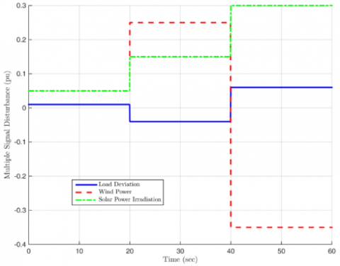
This scenario is one of the most difficult conditions to evaluate the performance of the controller. Several adversities are considered simultaneously. Load deflection is considered as the first disaster. Changes in load are common in all power systems and these changes are built into this scenario. The changes in the output power from the solar cell and wind turbine are other disasters that are considered simultaneously with the load change, and of course, all these changes are shown in Figure 11 as multiple disturbances. The results of applying the reset-fuzzy control method are shown in Figures 12 and 13. Figure 12 shows the amount of frequency deviation using the proposed, PI and PID controllers. As it is clear from the figure, in the times after the occurrence of changes and disturbances in production power and load, the fastest frequency recovery and removal of frequency deviation, frequency regulation and the shortest settling time occur by the planned reset-fuzzy controller. From this point of view, i.e. speed, PI and PID controllers are ranked next. This figure also shows that the PID method needs much more time than the other two approaches to perform frequency regulation, although the number of frequency response oscillations in the PID method is less. Another characteristic of the transient response is the amount of overshoot. The PI method shows a very high overshoot, while the PID and the fuzzy reset approaches have less and almost the same overshoot. In figures 13(a) and 13(b), respectively, the control signals obtained from applying different controllers are shown separately and on top of each other. This figure shows the smooth and flat behavior of the control signal obtained from the proposed reset-fuzzy and PI approaches, and of course, the PID technique has a sharper behavior in addition to the large signal range and of course has a higher slew rate.
Figure 11. The multiple disturbances in scenario 1
Figure 12. Frequency deviation under proposed, PI and PID controllers in scenario 1
(a)
(b)
Figure 13. Control signals using proposed, PI and PID controllers in scenario 1 (a) separately (b) on top of each other
Scenario 2
In this scenario, there are multiple disturbances in the load and power produced by PV and wind turbines, and of course, in order to create the most difficult working conditions to evaluate the performance of the controller, an uncertainty of 50% is also included in the D and M parameters of the microgrid. The simulation results in this scenario are shown in Figures 14 and 15. Figure 14 shows the frequency deviation and error. In this scenario, a behavior similar to scenario 1 is observed, that is, the lowest settling time, the highest speed of frequency recovery and performing the frequency regulatory action are obtained by the planned fuzzy reset method and of course, PI and PID methods show the highest frequency deviation and the highest settling time respectively. The dominant point of this scenario is the behavioral changes obtained from the PI and PID methods, because each of them has suffered from functional weaknesses compared to the previous scenario. The PI method requires more time to perform regulation, and in the PID method, unwanted fluctuations occur in the frequency behavior of the microgrid. In this scenario, the amount of overshoot and undershoot obtained from the planned reset- fuzzy technique is much less than the PI and PID methods, and this characteristic is another story of the superiority of the designed control approach. Figures 15(a) and 15(b) show the control signals obtained from the PI, PID and reset-fuzzy methods in two separate and superimposed states. The soft and smooth behavior of the PI and proposed reset- fuzzy controllers can be seen similar to scenario one. The sharp behavior with a large amplitude and of course more oscillations are among the characteristics of the control signal obtained by the PID method in the second simulation scenario.
Figure 14. Frequency deviation under proposed, PI and PID controllers in scenario 2
(a)
(b)
Figure 15. Control signals using proposed, PI and PID controllers in scenario 2 (a) separately (b) on top of each other
This paper presented a novel robust hybrid scheme for islanded microgrid frequency control. First, the model of an islanded microgrid explained in the presence of various elements and how it works and the interactions between different parts presented. Taking into account the basic considerations for performing frequency regulation which included the effects of model uncertainty, disturbances on the microgrid system, load changes, handling nonlinear dynamics, and of course the simplicity of the controller design, a hybrid robust approach designed for this purpose. The designed control technique included three parts: fuzzy, reset with fuzzy tune, and selector between fuzzy method and reset-fuzzy, which together formed an effective smart and robust scheme. To evaluate the performance of the controller, the scenarios that included the most severe occurrences of uncertainty and disturbance and changes in production power and load considered and the effectiveness and ability of the planned technique evaluated and confirmed from the point of view of achieving the regulatory goal and improving transient and permanent responses compared to other conventional control methods. Considering the limitation on the control signal, implementing the method on practical and reality microgrids, developing a control method for microgrid voltage management and also covering the effects of communication delay are among the most important directions of future studies.
[1] Jithin, S., & Rajeev, T. (2022). Investigation on microgrid control and stability. Smart Grids and Microgrids: Technology Evolution, 99-125, https://doi.org/10.1002/9781119760597.ch5.
[2] Gutiérrez-Oliva, D., Colmenar-Santos, A., & RosalesAsensio, E. (2022). A Review of the State of the Art of Industrial Microgrids Based on Renewable Energy. Electronics, 11(7), 1002, https://doi.org/10.3390/electronics11071002.
[3] Priyadharshini, N., Gomathy, S., & Sabarimuthu, M. (2020). A review on microgrid architecture, cyber security threats and standards. Materials Today: Proceedings, https://doi.org/10.1016/j.matpr.2020.10.622.
[4] Kiehbadroudinezhad, M., Merabet, A., Abo-Khalil, A. G., Salameh, T., & Ghenai, C. (2022). Intelligent and Optimized Microgrids for Future Supply Power from Renewable Energy Resources: A Review. Energies, 15(9), 3359, https://doi.org/10.3390/en15093359.
[5] Tomin, N., Shakirov, V., Kozlov, A., Sidorov, D., Kurbatsky, V., Rehtanz, C., & Lora, E. E. (2022). Design and optimal energy management of community microgrids with flexible renewable energy sources. Renewable Energy, 183, 903-921, https://doi.org/10.1016/j.renene.2021.11.024.
[6] Singh, P., Paliwal, P., & Arya, A. (2019, October). A review on challenges and techniques for secondary control of microgrid. In IOP Conference Series: Materials Science and Engineering (Vol. 561, No. 1, p. 012075). IOP Publishing, DOI 10.1088/1757-899X/561/1/012075.
[7] Ray, P. K., Mohanty, S. R., & Kishor, N. (2011). Proportional–integral controller based small-signal analysis of hybrid distributed generation systems. Energy Conversion and Management, 52(4), 1943-1954, https://doi.org/10.1016/j.enconman.2010.11.011.
[8] Latif, A., Hussain, S. S., Das, D. C., & Ustun, T. S. (2021). Design and Implementation of maiden dual-level Controller for Ameliorating Frequency Control in a Hybrid Microgrid. Energies, 14(9), 2418, https://doi.org/10.3390/en14092418.
[9] Shi, K., Cai, X., She, K., Zhong, S., Soh, Y., & Kwon, O. (2022). Quantized memory proportional–integral control of active power sharing and frequency regulation in island microgrid under abnormal cyber attacks. Applied Energy, 322, 119540, https://doi.org/10.1016/j.apenergy.2022.119540.
[10] Mallesham, G., Mishra, S., & Jha, A. N. (2011, December). Ziegler-Nichols based controller parameters tuning for load frequency control in a microgrid. In 2011 International Conference on Energy, Automation and Signal (pp. 1-8), IEEE, https://doi.org/10.1109/ICEAS.2011.6147128.
[11] Goya, T., Omine, E., Kinjyo, Y., Senjyu, T., Yona, A., Urasaki, N., & Funabashi, T. (2011). Frequency control in isolated island by using parallel operated battery systems applying H∞ control theory based on droop characteristics. IET renewable power generation, 5(2), 160- 166, https://doi.org/10.1049/iet-rpg.2010.0083.
[12] Veronica, A. J., & Kumar, N. S. (2017). Internal model based load frequency controller design for hybrid microgrid system. Energy Procedia, 117, 1032-1039, https://doi.org/10.1016/j.egypro.2017.05.225.
[13] Lal, D. K., & Barisal, A. K. (2017, August). Load frequency control of AC microgrid interconnected thermal power system. In IOP Conference Series: Materials Science and Engineering (Vol. 225, No. 1, p. 012090). IOP Publishing, DOI 10.1088/1757-899X/225/1/012090.
[14] Das, D. C., Roy, A. K., & Sinha, N. (2012). GA based frequency controller for solar thermal–diesel–wind hybrid energy generation/energy storage system. International Journal of Electrical Power & Energy Systems, 43(1), 262- 279, https://doi.org/10.1016/j.ijepes.2012.05.025.
[15] Kumar, R. H., & Ushakumari, S. (2014, March). Biogeography based tuning of PID controllers for Load Frequency Control in microgrid. In 2014 International Conference on Circuits, Power and Computing Technologies [ICCPCT-2014] (pp. 797-802), https://doi.org/10.1109/ICCPCT.2014.7054992.
[16] Gayatri, M. T. L., & Parimi, A. M. (2016, March). Mitigation of supply & load side disturbances in an AC Microgrid using UPQC. In 2016 IEEE 6th International Conference on Power Systems (ICPS) (pp. 1-6), https://doi.org/10.1109/ICPES.2016.7584116.
[17] Farrokhabadi, M., Cañizares, C. A., Simpson-Porco, J. W., Nasr, E., Fan, L., Mendoza-Araya, P. A., ... & Reilly, J. (2019). Microgrid stability definitions, analysis, and examples. IEEE Transactions on Power Systems, 35(1), 13- 29, https://doi.org/10.1109/TPWRS.2019.2925703.
[18] Alhelou, H. H., Hamedani-Golshan, M. E., Zamani, R., Heydarian-Forushani, E., & Siano, P. (2018). Challenges and opportunities of load frequency control in conventional, modern and future smart power systems: a comprehensive review. Energies, 11(10), 2497, https://doi.org/10.3390/en11102497.
[19] Haes Alhelou, H., Hamedani-Golshan, M. E., Njenda, T. C., & Siano, P. (2019). A survey on power system blackout and cascading events: Research motivations and challenges. Energies, 12(4), 682, https://doi.org/10.3390/en12040682.
[20] Tohid Banki , Faramarz Faghihi & Soodabeh Soleymani (2020) Frequency control of an island microgrid using reset control method in the presence of renewable sources and parametric uncertainty, Systems Science & Control Engineering, 8:1, 500-507, DOI: 10.1080/21642583.2020.1801533
[21] Linli W, Fatemi Golshan M. A novel fuzzy reset method for pressure control of proton exchange membrane fuel cell in the presence of uncertainty. Int J Energy Res. 2021;1-11. doi:10.1002/er.7309.
[22] Liu, Y. J., & Wang, W. (2007). Adaptive fuzzy control for a class of uncertain nonaffine nonlinear systems. Information Sciences, 177(18), 3901-3917, https://doi.org/10. 1016/j.ins.2007.03.005.