Abderrahim Touil*![]() | Fatima Babaa
| Fatima Babaa![]() | Frédéric Kratz
| Frédéric Kratz![]() | Ouafae Bennis
| Ouafae Bennis![]()
© 2024 The authors. This article is published by IIETA and is licensed under the CC BY 4.0 license (http://creativecommons.org/licenses/by/4.0/).
OPEN ACCESS
The main aim of this article is to achieve predictive maintenance by proposing reliable residuals specific to outer ring bearing faults. Our work falls within the general context of maintenance, with particular emphasis on vibration analysis techniques. For an in-depth study of the fault, we use spectral analysis of electromagnetic torque, which gives very satisfactory results compared with work based on line current or neutral voltage fault signatures due to the similarity in the mechanical nature of the fault and the signal to be studied. In fact, an analytical calculation of the electromagnetic torque has been developed to obtain the specific frequencies of the fault under consideration. To highlight our results, the simulation of the analytical calculation of this fault was implemented in MATLAB/SIMULINK using the Fast Fourier Transform method to extract fault signatures. The induction motor's performance was analyzed under various operating conditions, including both healthy and faulty states. Finally, an experimental study will support our analytical developments.
diagnosis, induction motors, line neutral voltage, outer ring bearing fault
The common use of asynchronous machines in the industrial context provokes various failures, both electrical and mechanical. These faulty situations are due to construction errors or exposure to various factors during operation. Then, failure analysis is of vital importance for industrial engineering and maintenance. The fundamental importance of having a good prognostic is in the type of data used to identify and solve the various problems. Electrical or mechanical signals for machine condition monitoring are diverse. several studies of the fault using current [1], phase voltage [2] or neutral voltage [3, 4], torque, or speed that are constantly used to monitor any potential anomalies. A study of asynchronous motor malfunctions has shown that they are classified according to their nature. We distinguish: Bearing faults at 41% [5, 6], stator faults at 37% [7, 8], rotor faults at 10% [9, 10], and other faults at 12% [11, 12].
Bearing faults are the most frequent faults in electrical machines, occurring as a result of lubricant contamination, excessive load, or electrical causes such as inverter-induced leakage current. It generally leads to several mechanical effects in machines, such as increased noise levels and vibrations caused by rotor movements around the machine's longitudinal axis. These faults also induce strong load torque oscillations that considerably affect the speed and power of the asynchronous machine. According to the literature, three main categories of bearing failure can be identified: outer ring bearing failure [13], inner ring bearing failure [14] and ball bearing failure [15].
One of the most important predictive maintenance techniques is vibration analysis, known as the most effective and accurate technique for diagnosis and monitoring. In fact, the analysis of rotating machine vibrations contains a great deal of information, which can be helpful to identify various faults by determining their type and degree of severity. Due to the mechanical nature of the fault, certain mechanical quantities like electromagnetic torque [16, 17], rotational speed [18, 19], mechanical vibration [20-22] or instantaneous power [23, 24] give relevant information on the state of health of the machine.
With this perspective, the aim of this paper is to diagnose mechanical signals through the estimation of the electromagnetic torque, the instantaneous power and the rotational speed of rotating electrical machines directly connected to the grid. The originality of the proposed method lies in the exploitation of the machine's magnetic field in the energy calculation. To estimate the electromagnetic torque we consider the co-energy, which is the complement of the energy stored in a magnetic circuit.
Through our development, we'll be able to determine an accurate fault indicator throw the normalized FFT spectrum. In comparison with the current signatures proposed for low-power induction machines mentioned in references [13, 14], the proposed fault indicator derived from electromagnetic torque is capable of indicating the presence of the fault.
At the end of this paper, experimental results support our analytical study.
Depending on the construction of the asynchronous motor, the stator windings are usually three-phase, fed by a balanced three-phase current system. The stator creates a system of alternating north and south poles, and the intersection of this system with the rotating fields created in the rotor bars generates an electromagnetic torque that drives the induction machine. In an induction machine that is depends on the air-gap geometry, there is a variation in permeance that engenders the variation of the Inductances.
It is well known that induction machine receives electrical energy 'Wel' from supplied voltage, and transforms it into work 'Wm' and heat 'Q'. Part of the energy is stored in the magnetic circuit, in the form of electromagnetic energy 'Wemg'.
The energy balance in absolute value is obtained by the following equation:
$d W_{e l}=d W_m+d Q+d W_{e m g}$ (1)
After entering the formula for transition point, A to B.
$W_{e l A \rightarrow B}=W_{m A \rightarrow B}+Q_{A \rightarrow B}+W_{e m g}(A)-W_{e m g}(B)$ (2)
The stored energy Wemg appears as the free energy of the system:
$d W_{e m g}=d W_{e l}-d W_m-d Q$ (3)
In our development, we neglect any energy dissipation in the form of heat, and we also consider as no saturation. Then, the magnetic induction in the air gap is the sum of that in the stator and in the rotor, so the energy is practically stored in the air gap. We have:
$d W_{e m g}=d W_{e l}-d W_m$ (4)
Co-energy $d W_{e m g}^{\prime}$ is defined as the complement of the energy stored in a magnetic circuit.
$d W_{\text {emg }}^{\prime}=d\left(\sum_k \Psi_{\mathrm{k}} \mathrm{i}_{\mathrm{k}}\right)-d W_{\text {emg }}$ (5)
According to $W_{e m g}$, we have:
$d W_{e m g}=u_s i_s d t+u_r i_r d t=-e_s i_s d t-e_r i_r d t$ (6)
We apply Faraday's law:
$-e_s=\frac{d \Psi_{\mathrm{s}}}{d t},-e_r=\frac{d \Psi_{\mathrm{r}}}{d t}$ (7)
Following development, we find:
$d W_{e m g}^{\prime}=d\left(\Psi_s i_s+\Psi_r i_r\right)-d W_{e m g}$ (8)
$d W_{e m g}^{\prime}=d \Psi_s i_s+\Psi_s d i_s+d \Psi_r i_r+\Psi_r d i_r-d W_{e m g}$ (9)
$d W_{e m g}^{\prime}=d\left(\Psi_s i_s+\Psi_r i_r\right)-d W_{e m g}$ (10)
Assuming the linearity of the magnetic circuit, we put:
$\Psi_{\mathrm{s}}=L_{s s} i_s+M_{s r} i_r, \Psi_{\mathrm{r}}=M_{s r} i_s+L_{r r} i_r$ (11)
After integrating the $d W_{e m g}^{\prime}$ formula:
$W_{\text {emg }}^{\prime}=\frac{1}{2} L_{s s} i_s{ }^2+\frac{1}{2} L_{r r} i_r{ }^2+M_{s r} i_s i_r$ (12)
In the matrix form:
$W_{e m g}^{\prime}=\frac{1}{2}\left[\begin{array}{ll}i_s & i_r\end{array}\right]\left[\begin{array}{cc}L_{s s} & M_{s r} \\ M_{s r} & L_{r r}\end{array}\right]\left[\begin{array}{l}i_s \\ i_r\end{array}\right]$ (13)
At the end, the relationship between magnetic energy and electromagnetic torque with respect to angle “θ” is:
$C_{e m}=-\left(\frac{\partial W_{e m g}^{\prime}}{\partial \theta}\right)$ (14)
$C_{e m}=-\frac{1}{2}\left[\begin{array}{ll}i_s & i_r\end{array}\right]\left[\begin{array}{cc}\frac{\partial L_{s s}}{\partial \theta} & \frac{\partial M_{s r}}{\partial \theta} \\ \frac{\partial M_{s r}}{\partial \theta} & \frac{\partial L_{r r}}{\partial \theta}\end{array}\right]\left[\begin{array}{l}i_s \\ i_r\end{array}\right]$ (15)
$C_{e m}=-\frac{1}{2} \frac{\partial L_{s s}}{\partial \theta} i_s{ }^2-\frac{1}{2} \frac{\partial L_{r r}}{\partial \theta} i_r{ }^2-i_s \frac{\partial M_{s r}}{\partial \theta} i_r$ (16)
The first two terms represent the reluctance torque that coexists with the variation in self-inductance when the stator or the rotor has salient poles. The third term represents the alignment torque, linked to the variation in mutual inductance. If we consider that the air gap is uniform the electromagnetic torque is:
$C_{e m}=-i_s{ }^T \frac{\partial M_{s r}}{\partial \theta} i_r$ (17)
3.1 Healthy condition
The mutual inductance between two windings “A” and “B” in a machine is given by the following relationship [25]:
$L_{A B}(\theta)=\mu_0 r l \int_0^{2 \pi} g^{-1}(\theta) N_A\left(\theta_s\right) N_B\left(\theta_r\right) d \theta$ (18)
where,
$\begin{gathered}\mid\left[M_{s r}\right]=\sum_{h=1}^{\infty} M_{s r}*\left[\begin{array}{ccc}\cdots & \cos \left(h p\left(\theta+k \alpha_r\right)\right) & \cdots \\ \cdots & \cos \left(h p\left(\theta+k \alpha_r\right)-h 2 \pi / 3\right) & \cdots \\ \cdots & \cos \left(h p\left(\theta+k \alpha_r\right)+h 2 \pi / 3\right) & \cdots\end{array}\right]\end{gathered}$ (19)
To calculate the electromagnetic torque, the following stator and the rotor currents are used:
$i_s\left(\theta_s\right)=I_s \sum_{i=1}^3 \cos \left(\theta_s-(i-1) 2 \pi / 3-\varphi\right)$ (20)
$i_r\left(\theta_r\right)=I_r \sum_{k=1}^{n b} \cos \left(\theta_r-k \alpha_r-\varphi\right)$ (21)
We obtain the healthy torque formula:
$\begin{gathered}C_{e m}=-\frac{1}{4} h p \sum_{i=1}^3 \sum_{h=1}^{\infty} \sum_{k=1}^{n b} M_h^{s r} \hat{I}_r \hat{I}_s \left(\sin \left(\theta_s+h p \theta+\theta_r+(h-1) k p \alpha_r\right.\right. -(h+1)(i-1) 2 \pi / 3-\varphi) \\ -\sin \left(\theta_s-h p \theta-\theta_r-(h-1) k p \alpha_r\right. -(h+1)(i-1) 2 \pi / 3-\varphi) \\ -\sin \left(\theta_s-h p \theta-\theta_r-(h-1) k p \alpha_r\right. +(h-1)(i-1) 2 \pi / 3-\varphi) \\ +\sin \left(\theta_s+h p \theta-\theta_r+(h+1) k p \alpha_r\right.-(h+1)(i-1) 2 \pi / 3-\varphi) \\ -\sin \left(\theta_s-h p \theta+\theta_r-(h+1) k p \alpha_r\right. +(h-1)(i-1) 2 \pi / 3-\varphi))\end{gathered}$ (22)
The healthy torque formula is a sum of several waves shifted by the term $(h \pm 1) k p a \pm(h \pm 1)(i-1) \frac{2 \pi}{3}$.
Extraction of the frequency orders for calculating the frequency components is done after replacing $\theta_s$, $\theta$ and $\theta_r$ with the following values:
$\theta=\frac{1-g}{p} \omega_s t, \theta_r=g \omega_s t, \theta_s=\omega_s t$
In this case, the torque is zero, except when condition “G” is fulfilled:
$G=\left\{h=6 k \pm\left. 1\right|_{k=1,2 . . .} \cap h=\frac{\lambda n_b}{p} \pm\left. 1\right|_{\lambda=0,1,2 . .}\right\}$ (23)
Specific frequencies components appear in the electromagnetic torque that are define as:
$\left\{\begin{array}{l}f_{s h}=\left( \pm \frac{\lambda n_b}{p}(1-g)\right) f_s \\ f_{s h}=\left(2 \pm \frac{\lambda n_b}{p}(1-g)\right) f_s\end{array}\right.$ (24)
3.2 Faulty condition
The mutual inductance in the presence of bearing outer ring defects, calculated in reference [13], is presented as follows:
$\begin{aligned} & {\left[M_{s r}\right]=\sum_{h=1}^{\infty} M_{s r}} \\ & {\left[\begin{array}{ccc}\cdots & \cos \left(h p\left(\theta+k \alpha_r\right)\right) & \ldots \\ \ldots & \cos \left(h p\left(\theta+k \alpha_r\right)-h 2 \pi / 3\right) & \ldots \\ \cdots & \cos \left(h p\left(\theta+k \alpha_r\right)+h 2 \pi / 3\right) & \ldots\end{array}\right]} \\ & +\sum_{h=1}^{\infty} M_{s r}^{h p \pm 1} \\ & {\left[\begin{array}{ccc}\cdots & \cos \left((h p \pm 1)\left(\theta+k \alpha_r\right)\right) & \ldots \\ \cdots & \cos \left((h p \pm 1)\left(\theta+k \alpha_r\right)-h 2 \pi / 3\right) & \ldots \\ \cdots & \cos \left((h p \pm 1)\left(\theta+k \alpha_r\right)+h 2 \pi / 3\right) & \ldots\end{array}\right]} \\ & +\sum_{h=1}^{\infty} M_{s r}^{o u t} \\ & {\left[\begin{array}{ccc}\cdots & \cos \left((h p \pm 1)\left(\theta+k \alpha_r\right) \pm \lambda \theta_{\text {out }}\right) & \cdots \\ \cdots & \cos \left((h p \pm 1)\left(\theta+k \alpha_r\right)-h 2 \pi / 3 \pm \lambda \theta_{\text {out }}\right) & \cdots \\ \cdots & \cos \left((h p \pm 1)\left(\theta+k \alpha_r\right)+h 2 \pi / 3 \pm \lambda \theta_{\text {out }}\right) & \cdots\end{array}\right]} \\ & \end{aligned}$ (25)
The electromagnetic torque in this case will be calculated through the stator current at Eq. (20) and the following rotor current:
$\begin{gathered}i_{r-d e f}\left(\theta_r\right)=I_r \sum_{k=1}^{n b} \cos \left(\theta_r-k \alpha_r-\varphi\right) +I_r^{h p \pm 1} \sum_{k=1}^{n b} \cos \left(\theta_r^{h p \pm 1}-(p+1) k \alpha_r-\varphi\right) +I_r^{\text {out }} \sum_{k=1}^{n b} \cos \left(\theta_r^{h p \pm 1}-(p+1) k \alpha_r+\lambda \theta_{\text {out }}-\varphi\right)\end{gathered}$ (26)
where,
$\theta_r^{h p \pm 1}=\left(g \mp \frac{1-g}{p}\right)$
We obtain the formula Eq. (27) for the electromagnetic torque in the faulty state:
$C_{\text {em-def }}=-i_s^T \frac{\partial\left[M_{s r}\right]_{\text {def }}}{\partial \theta} i_{r-d e f}$ (27)
After a mathematical development, the electromagnetic torque formula becomes a sum of multiple waves, producing a new frequency series in addition to the frequencies found for the healthy state. We have:
$\begin{gathered}f_{\text {sh }}=\left( \pm \frac{\lambda n_b}{p}(1-g)\right) f_s \pm \lambda f_{\text {out }} \\ f_{\text {sh }}=\left(2 \pm \frac{\lambda n_b}{p}(1-g)\right) f_s \pm \lambda f_{\text {out }} \\ f_{\text {sh }}=\left( \pm \frac{\lambda n_b}{p}(1-g)\right) f_s \pm 2 * \lambda f_{\text {out }} \\ f_{\text {sh }}=\left(2 \pm \frac{\lambda n_b}{p}(1-g)\right) f_s \pm 2 * \lambda f_{\text {out }}\end{gathered}$ (28)
The motor characteristics used in the simulation are 2 pole pairs (p ≠ 1), 3 phases, 50 Hz with 22 rotor bars. The motor is tested for various operating states.
The spectrum results were computed with Fast Fourier Transform, all results were obtained with MATLAB software. With motor parameters showed in Table 1 and bearing parameters: Series 6205 bearing (Bd= 7.56 mm, Pd= 41 mm, Nb=9).
Table 1. The motor parameters
|
Motor Parameters |
Correspondent Value |
|
Supply voltage Pairs of poles per phase Rotor bars Stator resistance Rotor bar resistance Rotor end ring resistance Stator inductance Rotor bar inductance Rotor end ring inductance Inertia Fundamental frequency Stator slots |
$V m=230 * \operatorname{sqrt}(2) V$ $p=2$ $N=22$ $R s=6.85$ $R b=19.2 E-5$ $R a=3.2 E-6$ $l l s=0.0424$ $L b=4.39 E-7$ $L a=6.204 E-9$ $J J=6.2 E-3$ $f=50$ $N s=24$ |
|
Winding factor parameters |
$N e=2$ $N t=280$ $Q=6$ |
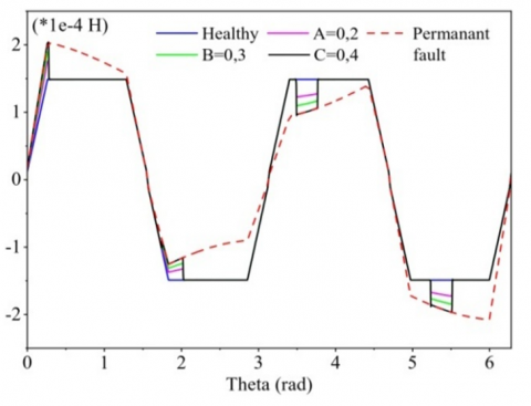
Figures 1 and 2 illustrate the impact of defects on mutual inductance, in particular the changes in inductance values under different levels of defects. In these figures, the deformation term refers to changes in mutual inductance resulting from the presence of defects. In Figure 1, the described variations in mutual inductance under different fault levels suggest a perceptible impact of faults on inductance values, which means potential implications for the overall behavior of the power system.
Figure 1. Mutual inductance at different fault levels
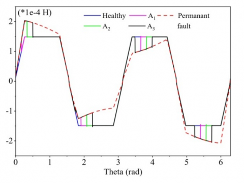
Figure 2 similarly illustrates variations in mutual inductance, focusing on specific fault angles or fault conditions. The deformations observed in both figures underline the importance of understanding how faults affect mutual inductance, providing valuable insights into the severity and importance of such faults in the context of system reliability.
Figure 2. Mutual inductance under different fault angles
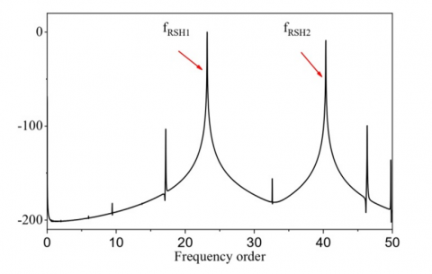
Figure 3. Normalized spectrum of electromagnetic torque (Healthy state)
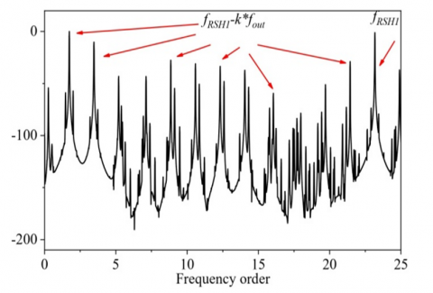
Figure 4. Normalized spectrum of electromagnetic torque (Faulty state)
Figure 3 shows a representation of the normalized electromagnetic torque spectrum, which gives an indication of the state of health of the induction machine. The spectrum highlights the presence of specific harmonics, and their appearance is justified analytically by Eq. (24). This analytical approach highlight the relationship between the rotor slots distribution parameter “nb”and the resulting harmonics in the electromagnetic torque.
In Figure 4, the appearance of harmonics is revealed by analytical calculations aimed at extracting the frequencies of the electromagnetic torque in the presence of this specific condition “outer ring bearing fault (ORBF)”. The figure illustrates the appearance of harmonics associated with the outer ring bearing fault (ORBF), and their presence is justified analytically using Eq. (28). And with the comparison with harmonics related to the distribution of rotor slots in the healthy state, Eq. (28) gives valuable insights into how the fault condition affects electromagnetic torque frequencies. The appearance of these harmonics is based on the extracted formulas $\pm \lambda f_{\text {out }}$ or $\pm 2*\lambda f_{\text {out }}$ around healthy state frequencies.
To validate the proposed model and to diagnose outer ring bearing faults we propose to analyze electromagnetic torque. We synthesize data from experimental tests with a 1.1 kW squirrel cage induction motor.
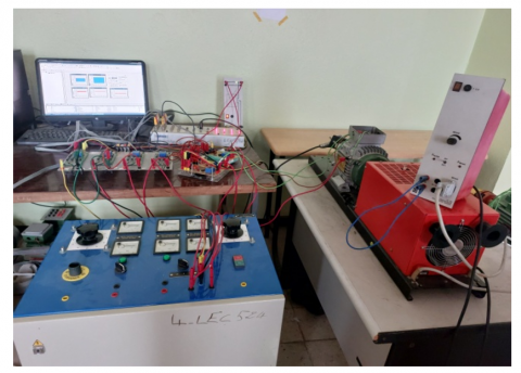
Figure 5. Test bench
The motor tested is a three-phase induction motor with 24 stator slots, 22 rotor bars and 2 pole pairs, manufactured by FIMET. The bearing tested is series 6205 (Bd= 7.56 mm, Pd= 41 mm, N=9). It is loaded from a magnetic powder brake.
The electromagnetic torque was measured using three LV 25-P voltage and current sensors, their data sheet indicating this principal information (Sensitivity25 mV/V, accuracy =0.9%, bandwidth 100 kHz), speed encoder (The STM32 timer) and a data acquisition system (dSPACE) with a sampling frequency of 50 kHz and a data signal length of 5 seconds (see Figure 5).
We chose not to use the torque sensor, as its installation on the axis of rotation between the asynchronous motor and the powder brake is not recommended in an industrial environment. So, we opted for another, more practical method of measurement to confirm and obtain an estimated torque value applicable in an industrial environment.
Electromagnetic torque Cem drives the rotor at speed $\Omega$ and thus transmits a total mechanical power Pm. We have:
$C_{e m}=\frac{P_{e m}}{\Omega}, P_{e m}=P_m *(1-g)$ (29)
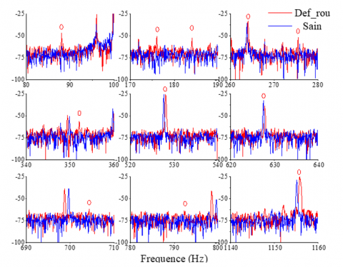
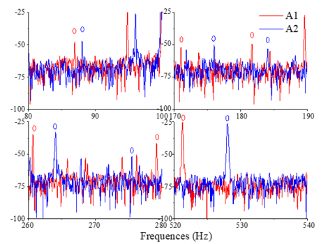
As long as the signal is analyzed on the basis of frequency, the torque amplitude is irrelevant, so we can neglect losses and estimate the torque signal. Figure 6 and Figure 7 illustrate some of the characteristic harmonics associated with bearing outer ring defects. These harmonics have been calculated using formulas established from the proposed analytical study.
Study of electrical quantities for detection and diagnosis electrical faults like unbalanced supply voltage [4], inter-turn short-circuit faults [8] or a rotor winding problems, is more appropriate and adequate to propose effective fault indicators. However, we notice that mechanical faults have a more particular influence on mechanical quantities which are the same nature [7]. As a result, detection and diagnosis of this type of fault will result in more obvious ripples in electro torque, speed or even instantaneous power, rather than their unobserved influence on current. Therefore, the distinct nature of mechanical problems calls for a more capable approach that gives priority to the analysis of mechanical signals in order to obtain superior diagnostic results.
Figure 6. Experimental result of the electromagnetic torque spectrum
Figure 7. Characteristic frequencies for different degrees of fault in the electromagnetic torque spectrum
The results of our study indicate that electromagnetic torque analysis is particularly sensitive to mechanical anomalies.
Our experimental tests have revealed that the torque contains riches of crucial information concerning this specific defect.
Based on the analytical results obtained, we have developed a specific reliability index to accurately detect and distinguish outer ring defects. Table 2 summarizes the results obtained after the application of the fault.
Where “λ” is the rank that defines the order of the RSH harmonics and “K” is the order of the harmonics associated with these RSHs.
Table 2. The harmonics of the outer ring bearing fault
|
$\lambda$ |
K |
The Associated Harmonics |
|
$\lambda=0$ |
$K=1$ $K=2$ $K=3$ $K=4$ $K=6$ $K=7$ $K=8$ |
$\left(0 *(1-g) f_s\right)+1 * f_{\text {ext }}=88$ $\left(0 *(1-g) f_s\right)+2 * f_{\text {ext }}=176$ $\left(0 *(1-g) f_s\right)+3 * f_{\text {ext }}=264$ $\left(0 *(1-g) f_s\right)+4 * f_{\text {ext }}=352$ $\left(0 *(1-g) f_s\right)+6 * f_{\text {ext }}=528$ $\left(0 *(1-g) f_s\right)+8 * f_{\text {ext }}=704$ $\left(0 *(1-g) f_s\right)+9 * f_{e x t}=792$ |
|
$\lambda=1$ |
$K=2$ $K=3$ $K=4$ $K=5$ |
$11 *(1-g) f_s-2 * f_{\text {ext }}=352$ $11 *(1-g) f_s-3 * f_{\text {ext }}=264$ $11 *(1-g) f_s-4 * f_{\text {ext }}=176$ $(13-11 g) f_s-4 * f_{\text {ext }}=276$ $11 *(1-g) f_s-5 * f_{\text {ext }}=88$ $(13-11 g) f_s-5 * f_{\text {ext }}=188$ |
|
$\lambda=2$ |
$K=6$ $K=10$ |
$(24-22 g) f_{\mathrm{s}}-6 * f_{\text {etx }}=628$ $(24-22 g) f_s-10 * f_{\text {ext }}=276$ |
Notes: speed test =1440 rpm.
This paper presents an analytical study of electromagnetic torque under different monitoring conditions (healthy machine and under an outer ring bearing fault). The proposed analytical development is based on the winding function approach. To take into account the presence of the outer ring bearing defect, the details of the calculation and the development of the various inductances of the squirrel-cage asynchronous machine are also highlighted. As the fault under study is of mechanical origin, the calculation of electromagnetic torque is more appropriate for detecting bearing faults. It is difficult to attribute and understand what are the specific spectral lines related to a particular fault based on experimental results alone. Then it is important, to understand the genesis of the frequencies at the start of the fault. That is why the presentation of an analytical study of the torque taking into account the presence of the bearing fault is essential. The validation of our calculation results by simulation of the various quantities and also the visualization of the electromagnetic torque spectrum enabled us to say that this type of defect is detectable by determining the specific frequencies generated by the defect. A series of experimental results are presented to validate our various mathematical developments. We note that the electromagnetic torque spectrum is highly representative of mechanical defects. The study of bearing defects shows us a torque spectrum rich in information, with residues specific to the defect. These specific harmonic indicators make it possible to detect the presence of the bearing fault and optimizing predictive maintenance. However, it would be appropriate to accompany this present paper with other calculations making it possible to quantify the fault.
|
is, ir |
stator and rotor currents components, A |
|
$\psi_S, \psi_r$ |
stator and rotor flux components, wb |
|
Lss, Lrr |
stator and rotor inductances, H |
|
Msr |
mutual inductance, H |
|
Cem |
electromagnetic torque, Nm |
|
NA, NB |
distribution functions |
|
$g^{-1}(\theta)$ |
perméance fonction |
|
nb |
number of rotor slots |
|
$\alpha_r$ |
distance between two rotor bars |
|
h, λ |
rank of harmonics |
|
k |
rotor bar index |
|
g |
slip |
|
p |
number of pole pairs |
|
fs |
stator variables frequency, Hz |
|
$\theta_s, \theta_r, \theta$ |
stator, rotor and rotating field pulsations, rad |
|
$\theta_{\text {out }}$ |
fault’s pulsation, rad |
|
$\gamma$ |
fault’s angle, deg |
|
fout |
fault’s frequency, Hz |
|
$\Omega$ |
mechanical speed, rpm |
|
Pm |
mechanical power, kg. m2.s-3 |
[1] Mehala, N., Dahiya, R. (2007). Motor current signature analysis and its applications in induction motor fault diagnosis. International Journal of Systems Applications, Engineering & Development, 2(1): 29-35.
[2] Khaneghah, M.Z., Alzayed, M., Chaoui, H. (2023). Fault detection and diagnosis of the electric motor drive and battery system of electric vehicles. Machines, 11(7): 713. https://doi.org/10.3390/machines11070713
[3] Barmpatza, A.C. (2023). The neutral voltage difference signal as a means of investigating eccentricity and demagnetization faults in an AFPM synchronous generator. Machines, 11(6): 647. https://doi.org/10.3390/machines11060647
[4] Touil, A., Babaa, F. (2022). Studying of unbalanced supply voltage effects on three phase induction motor performances based on line neutral voltage analytical calculation. In 5th International Conference on Electrical Engineering and Control Applications ICEECA’22, Khenchela, Algeria.
[5] Blodt, M., Granjon, P., Raison, B., Rostaing, G. (2008). Models for bearing damage detection in induction motors using stator current monitoring. IEEE Transactions on Industrial Electronics, 55(4): 1813-1822. https://doi.org/10.1109/TIE.2008.917108
[6] Li, B., Chow, M.Y., Tipsuwan, Y., Hung, J.C. (2000). Neural-network-based motor rolling bearing fault diagnosis. IEEE Transactions on Industrial Electronics, 47(5): 1060-1069. https://doi.org/10.1109/41.873214
[7] Laamari, Y., Allaoui, S., Bendaikha, A., Saad, S. (2021). Fault detection between stator windings turns of permanent magnet synchronous motor based on torque and stator-current analysis using FFT and discrete wavelet transform. Mathematical Modelling of Engineering Problems, 8(2): 315-322. https://doi.org/10.18280/mmep.080220
[8] Touil, A., Babaa, F., Ouamane, M. R., Bennis, O., Kratz, F., Hadjami, M. (2021). Analytical calculation of inductances under stator inter-turn short circuits fault condition in operating squirrel cage induction motors. In 2021 9th International Conference on Systems and Control (ICSC), Caen, France, pp. 113-118.https://doi.org/10.1109/ICSC50472.2021.9666577
[9] Chouidira, I., Khodja, D.E., Chakroune, S. (2020). Fuzzy logic based broken bar fault diagnosis and behavior study of induction machine. Journal Européen des Systèmes Automatisés, 53(2): 233-242. https://doi.org/10.18280/jesa.530210
[10] Reda, R., Fayçal, A., Tahar, B. (2017). Fault eccentricity diagnosis in variable speed induction motor drive using DWT. Advances in Modelling and Analysis C, 72(3): 181-202.https://doi.org/10.18280/ama_c.720301
[11] Akin, B., Orguner, U., Toliyat, H. A., Rayner, M. (2008). Low order PWM inverter harmonics contributions to the inverter-fed induction machine fault diagnosis. IEEE Transactions on Industrial Electronics, 55(2): 610-619. https://doi.org/10.1109/TIE.2007.911954
[12] Obaid, R.R., Habetler, T.G., Tallam, R.M. (2003). Detecting load unbalance and shaft misalignment using stator current in inverter-driven induction motors. In IEEE International Electric Machines and Drives Conference IEMDC'03, Madison, WI, USA, pp. 1454-1458. https://doi.org/10.1109/IEMDC.2003.1210643
[13] Touil, A., Babaa, F., Bennis, O., Kratz, F. (2021). Analytical model for separated frequency signature of outer race bearing fault from static eccentricity. North Atlantic University Union: International Journal of Circuits, Systems and Signal Processing, pp. 1821-1827. https://doi.org/10.46300/9106.2021.15.196
[14] Hadjami, H., Razik, H., Oumaamar, M.E.K., Kezzar, A. (2018). Analytical model of cage induction machine dedicated to the study of the inner race bearing fault. International Journal of Electrical and Computer Engineering, 8(1): 458. https://doi.org/10.11591/ijece.v8i1.pp458-471
[15] Bediaga, I., Mendizabal, X., Arnaiz, A., Munoa, J. (2013). Ball bearing damage detection using traditional signal processing algorithms. IEEE Instrumentation & Measurement Magazine, 16(2): 20-25. https://doi.org/10.1109/MIM.2013.6495676
[16] Kutsyk, A., Korkosz, M., Semeniuk, M., Nowak, M. (2023). An influence of spatial harmonics on an electromagnetic torque of a symmetrical six-phase induction machine. Energies, 16(9): 3813. https://doi.org/10.3390/en16093813
[17] Güemes, J.A., Iraolagoitia, A.M., Del Hoyo, J.I., Fernandez, P. (2010). Torque analysis in permanent-magnet synchronous motors: A comparative study. IEEE Transactions on Energy Conversion, 26(1): 55-63. https://doi.org/10.1109/TEC.2010.2053374
[18] Singh, G.K. (2003). Induction machine drive condition monitoring and diagnostic research—A survey. Electric Power Systems Research, 64(2): 145-158. https://doi.org/10.1016/S0378-7796(02)00172-4
[19] Kim, J.G., Park, Y.J., Kim, I.J., Kim, Y.K. (2011). Characteristics analysis of induction generator with a change in rotor speed. The Transactions of The Korean Institute of Electrical Engineers, 60(12): 2225-2229. https://doi.org/10.5370/KIEE.2011.60.12.2225
[20] Lee, C.W. (1993). Vibration Analysis of Rotors (Vol. 21). Springer Science & Business Media.
[21] Wang, C., Lai, J.C.S. (1999). Vibration analysis of an induction motor. Journal of Sound and Vibration, 224(4): 733-756. https://doi.org/10.1006/jsvi.1999.2208
[22] McFadden, P.D., Smith, J.D. (1984). Model for the vibration produced by a single point defect in a rolling element bearing. Journal of Sound and Vibration, 96(1): 69-82. https://doi.org/10.1016/0022-460X(84)90595-9
[23] Kia, S.H., Mabwe, A.M., Henao, H., Capolino, G.A. (2006). Wavelet based instantaneous power analysis for induction machine fault diagnosis. In 32nd Annual Conference on IEEE Industrial Electronics, Paris, France, pp. 1229-1234. https://doi.org/10.1109/IECON.2006.347461
[24] Huang, J.J. (2020). Vibration testing of a certain turbojet engine using the power spectrum analysis. Journal Européen des Systèmes Automatisés, 53(1): 87-93. https://doi.org/10.18280/jesa.530111
[25] Khezzar, A., Hadjami, M., Bessous, N., Oumaamar, M.E.K., Razik, H. (2008). Accurate modelling of cage induction machine with analytical evaluation of inductances. In 2008 34th Annual Conference of IEEE Industrial Electronics, Orlando, FL, USA, pp. 1112-1117. https://doi.org/10.1109/IECON.2008.4758110