Karrar Haider Tajaldin*![]() | Hassan Jassim Motlak
| Hassan Jassim Motlak![]()
© 2024 The authors. This article is published by IIETA and is licensed under the CC BY 4.0 license (http://creativecommons.org/licenses/by/4.0/).
OPEN ACCESS
This research aims to enhance the efficiency of photovoltaic systems by proposing two innovative methods for maximum power point tracking (MPPT). We used the beluga whale optimization (BWO) algorithm, so we can adjust the gain of the PI controller. Volatility around MPP and failure accuracy under rapidly changing isolation are among the known drawbacks of traditional MPPT algorithms. To overcome these drawbacks, we proposed a theory that combines Perturb and Observe (P&O) with BWO, based on the controller of proportional integration (PI) and fractional order proportional integration (FOPI). The study compares the new techniques with existing traditional algorithms such as P&O and IC in terms of their efficiency, complexity and ease of implementation. Simulation tests conducted using Matlab indicate that the proposed hybrid FOPI-BWO method achieves an average tracking efficiency of about 97.05% and a voltage gain of 2.348, in the PI-BWO method it achieves an efficiency of 96.12% and a voltage gain of 2.322, and the IC-MPPT theory achieves an efficiency of 95.5% and a voltage gain of 2.261. , while the P&O-MPPT theory achieved an efficiency of 94.02% and a voltage gain of 2.241.It is clear that the two proposed algorithms perform better than traditional algorithms in terms of energy overshoot, ripple, and response time.
photovoltaic system, maximum power point tracking, P&O, incremental conductance, fractional order proportional integral, and beluga whale optimization
Efforts have been focused on the use of renewable energy due to recent technological advancements, rising environmental pollution, and global warming. Wind and solar power are the most significant. Researchers are mainly interested in renewable energy systems to make maximum use of the energy produced from the sun, and since solar panels generate continuous voltage, the most important problems that occur are the low level of voltage and the fluctuation of the output voltage [1]. Researchers began developing systems to extract as much energy as possible from renewable energy sources, especially from photovoltaic cells. Mechanical systems that drive the photovoltaic cells have been developed so that they receive the greatest amount of solar radiation, to achieve maximum power. Creating a photovoltaic system for grid-connected applications includes the following five basic elements: 1) A solar-powered photovoltaic array that produces electricity, 2) DC-DC converter, which transforms low DC voltages generated by solar cells into high DC voltage, 3) DC-ac inverter, which transforms high DC voltage into single or three phase AC voltage, 4) An AC filter that absorbs the voltage/current harmonics produced by the inverter, and 5) a digital controller that manages the converter's operation and can track the maximum power point MPPT [2]. The main technical requirements for the development of a practical PV system include a) Perfect control that can extract maximum output power from the photovoltaic cells under all operating conditions and weather, b) A high performance-to-cost ratio to facilitate the commercialization of developed PV technologies. Developing a photovoltaic cell system that can meet these technical requirements is technically challenging because photovoltaic cells have a very non-linear property, meaning that their performance changes with operating conditions such as ambient temperature or insolation [2]. The operating conditions in these systems determine how well the photovoltaic system performs. Subsequently, taking into account the efficiency of the photovoltaic constant, the maximum power extracted from the photovoltaic cells is highly dependent on three factors: insolation, cell temperature (ambient temperature), and load profile (load resistance) [3]. Another sort of tracer known as maximum power point tracking (MPPT) moves the operational photovoltaic voltage, or current. In order to sweep the PV power with this tracker. There are now a lot of maximum power point tracking designs and algorithms accessible in the literature. Every technique has its own restrictions, requirements, and uses. It is important to note that the maximum power point tracking is a tool utilized for a variety of renewable energy sources, including fuel cells and thermoelectric devices, in addition to solar cells [4]. A wide range of maximum power point tracking algorithms have been proposed in the past. The Perturb and Observation method, also known as the P&O method, is one of the frequently used algorithms. Other methods include the Constant voltage method, the Incremental conduction method, and the DC method. Using this method, the photovoltaic array's voltage or current is tuned to reach the maximum power point (MPP). For instance, when the voltage keeps rising, the power also rises [5]. This paper reviews two innovative technologies for tracking peak power points of PV systems: BWO-PI with P&O MPPT and BWO-FOPI with P&O MPPT.
Here, we detail how previous researchers have kept tabs on the maximum power point. In Calvinho et al. [6] prevent steady-state oscillations, this article details a method for MPPT monitoring that employs a particle swarm optimization (PSO) algorithm with a tunable step size. As a result, the efficiency loss caused by partial shading of a PV system will be reduced. The solar panels' output is increased using a DC-DC boost converter. The PSO algorithm was modeled after the natural behavior of birds flocking together In Amara et al. [7] explain how a maximum power point tracking (ANFIS-MPPT) algorithm coupled with a proportional-integral (PI) controller can be used to optimize the performance of a photovoltaic panel system in variable environmental conditions. In this research, Matlab/Simulink was used to introduce and develop the mathematical concepts of the ANFIS method. The effectiveness of this ANFIS-MPPT method is demonstrated by contrasting the results with those obtained using a more traditional (Perturb & Observe) P&O-MPPT strategy. Results also demonstrate that the ANFIS-MPPT command outperforms the P & O-MPPT command across various irradiance conditions, demonstrating acceptable dynamic operations, faster convergence, and less variation of a working point close to MPP. Mahdi et al. [8] track the maximum power point of PV modules, this study will compare the efficacy of conventional Perturb and Observe (P&O) methods with those of soft computing methods (fuzzy Logic and adaptive neuro-fuzzy inference system) (MPPT). To model and simulate the MPPT system, an MSX-64 PV module and a boost DC-DC converter were used. The ANFIS controller showed responsiveness to weather fluctuations. Abderrahim et al. [9] have developed two new intelligent maximum power point tracking (MPPT) techniques for solar photovoltaic (PV) systems are lacking. Optimizing the duty cycle of the PWM driving the DC/DC optimization converter, we used two optimization algorithms: whale optimization algorithm (WOA) and grey wolf optimization (GWO) to successfully adjust the gain of the PID controller. In the simulation results section, we can clearly see that the two proposed algorithms perform better than traditional algorithms in terms of energy overshoot, ripple, and response time.
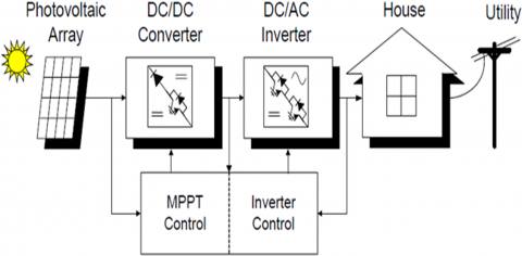
To meet the full power delivery of the load and increase the output voltage of the photovoltaic (PV) system, maximum power point tracking, or MPPT, is used in the system as shown in Figure 1. Photovoltaic power generation systems are becoming more and more popular due to their numerous benefits, which include virtually no pollution, no fuel costs, low maintenance, and no noise emission [10]. In this paper, we propose to use adaptive pi and P&O MPPT to control an ultra-thin positive-output Luo inverter, which features low output voltage ripple and high efficiency, as a way to implement an off-grid PV system for remote areas. When using MPPT control, it can operate with a gain many times greater than the input voltage at a very low duty cycle.
Figure 1. Block diagram of photovoltaic power system [3]
2.1 Topology of PV model
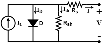
Using one or more solar panels—photovoltaic panels are primarily composed of solar cells—a photovoltaic device transforms solar energy into electrical energy. Relying on the required voltage and current, the solar cells are connected in series or parallel. Figure 2 depicts a circuit diagram of the PV model. Connecting the solar cells in series increases the panel's voltage, while placing them in parallel increases its current value [11].
Figure 2. PV model circuit [12]
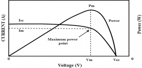
The P-V and I-V characteristics of the PV system are nonlinear. The two main variables affecting a photovoltaic device's performance are temperature and intensity of irradiation. Variations in temperature and radiation level are reflected in the voltage and current produced by the photovoltaic device. The nominal operating conditions of the solar module are 25℃ temperature and 1000 W/m2 (G=1) irradiation; The P-V and I-V characteristics of a PV cell are shown in Figure 3 [10]. When I=O, a cell's maximum voltage is known as the open-circuit voltage (VOC), and when V=O, the current that is part of a short circuit is known as the short-circuit current (ISC). The Maximum Power Point (MPP) is the single point during service when the PV cell generates its maximum power. $I_m, V_m$ and $P_m$ on the graph stand for the solar cell's maximum current, maximum voltage, and maximum power, respectively. The output current of an ideal cell expressed mathematically [13, 14] is:
$I=I_{P V}-I_d$ (1)
Figure 3. I-V and P-V characteristics of solar cell [15]
The Shockley equation is represented by $I_d$, the model's shunt resistance is represented by $R_{s h}$, and the light-generated current, which is proportional to solar irradiation, is represented by $I_{P V}$. Solar irradiation and the solar cell's work temperature, which is expressed in degrees Celsius, are the main factors influencing the light produced by the cell.
$I_{P V}=\left[I_{S C}+K_I\left(T_C-T_R\right)\right] \cdot G$ (2)
The cell's short-circuit current at (25℃) and (G=1) is represented by $\left(I_{SC}\right)$, its temperature coefficient for the short-circuit current is KI, and its reference and working temperatures are Tr and Tc, respectively. Here is the Shockley equation:
$I_d=I_S\left\{\exp \left(\frac{q}{A K T c}\right)-1\right\}$ (3)
$I=I_{P V}-I_d-I_P$ (4)
$I=I_{P V}-I_S\left\{\exp \left(\frac{q}{A K T C}\right)-1\right\}-\frac{V+I R_{s e}}{R_P}$ (5)
The solar cells must be connected in a series-parallel configuration in order to produce the necessary output power. With (Ns) being the number of modules connected in sequence and (Np) being the number of modules connected in parallel, and q representing the electron charge [1.60 × 10⁻¹⁹ C] and k denoting the Boltzmann constant [1.38 × 10⁻²³J/K], we have the following generalized PV array mathematical equation:
$I=I_{P V} N_P-I_S N_P\left\{\exp \left(\frac{q V}{A K T c N s}+\frac{I R_{s e}}{N_P}\right)-1\right\}$ (6)
$I_s=I_{r s}\left(\frac{T_c}{T_r}\right)^3 \exp \left[\frac{q E_g}{A_k}\left(\frac{1}{T_c}-\frac{1}{T_r}\right)\right]$ (7)
where, $\left(I_{r s}\right)$ is a cell's reverse saturation current at a reference temperature and solar radiation, and $(\mathrm{Eg})$ is the semiconductor's bandgap energy. At $25^{\circ} \mathrm{C},(\mathrm{Eg})$ for polycrystalline $\mathrm{Si}$ is approximately $1.12 \mathrm{eV}$ [14-16]. The reverse saturation current $\left(I_{r s}\right)$ of a cell can be computed using the Eq. (8).
$I_{R S}=\frac{I_{S C}}{\exp \left(\frac{q}{A K T_{C(n)} N_S} V o\right)-1}$ (8)
To maintain constant outputs under load conditions, DC-DC converters employ a variety of switching control techniques. It needs high efficiency, low ripple, and steady voltage. Along with adjusting the voltage up or down based on the load circumstances. The department of oversight's practical role in this. Numerous control circuits are present. Everyone has benefits, drawbacks, and unique applications [17]. PV systems use DC-DC step-up converters to boost and regulate the voltage produced by the PV modules. The POSLC is composed of one switch (S), one inductor (L), capacitors (C2&Co), and two diodes. The POSL) circuit architecture is shown in Section 3.1 along with its modelling Eq. (9) (on-state) and Eq. (10) (off-state) for output voltage gain display [18]:
$\operatorname{Vin}=V L=V c 1=L \Delta i / d t$ (9)
$\Delta i=V L(1-D) T / L=V o-2 \operatorname{Vin}(1-D) T / L$ (10)
$G=\frac{V o}{V i n}=\frac{2-D}{1-D}$ (11)
2.2 Perturb and Observe (P&O)
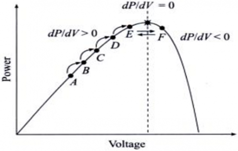
Because of its straightforward design and ease of implementation, the perturbation and monitoring algorithm is one of the most widely used techniques for maximum power point monitoring. When the PV array's current or operating voltage is altered, P&O technology regulates the PV array's performance and disturbance (increase or decrease) [19]. As demonstrated in Figure 4, the P&O algorithm is a hill-climbing technique that locates the peak of the power curve upon activation of the electrical array. There are just two detectors used in P&O technology. It works by disturbing (changing) the operating point of the solar panel and monitoring the resulting change in power output. The algorithm then adjusts the operating point to move towards the Maximum Power Point (MPP). This technology calculates power using photoelectric current and voltage sensing, modifies the voltage, and then monitors the impact of the generated power. The system oscillates in order to lessen oscillation after reaching the maximum power point. Reduce the step size of the disturbance. The shift in the function cycle is the largest step if the operating point is far from the MPP [20].
Figure 4. P&O method [20]
2.3 Incremental Conductance (INC)
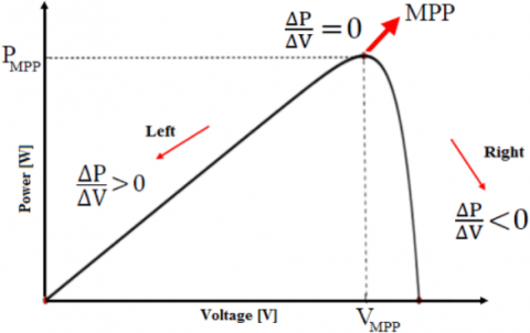
The tracking algorithm in the INC approach tracks MPP based on the slope of the PV module characteristic curve. When the slope is 0, the operational point is at the MPP, a positive slope places it to the left of the MPP, while a negative slope places it to the right of the MPP [21]. The work of the IC algorithm can be illustrated in Figure 5. The IC algorithm monitors the current and voltage of the PV panel using sensors. Through the sensors can know the maximum operating point [22].
Figure 5. Incremental conductance [22]
2.4 Adaptive proportional integral (PI) with P&O
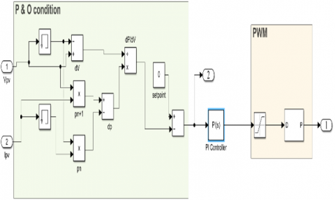
The adaptive PI control algorithm is a feedback control strategy widely used in engineering applications. It adjusts proportional and integral gains based on system dynamics, ensuring optimal performance under different conditions. Unlike a fixed PI controller, the adaptive version dynamically adjusts its parameters in response to changes in the system, making it suitable for applications with different operating conditions or parameters. Adaptive PI control is known for its ability to maintain stability and optimal performance in the face of uncertainties, parameter variations, or disturbances [23]. The adaptive nature of the PI controller complements the inherent simplicity of the P&O algorithm. By integrating the two, the control system can harness the adaptability of the PI controller to mitigate P&O constraints, such as oscillations around the MPP. BWO chosen because it provides an optimization framework that can tune the parameters of both the adaptive PI controller and the P&O algorithm, attempting to achieve an optimal balance between adaptability and efficiency. The combination of adaptive PI and P&O with beluga optimization may provide an adaptable solution suitable for a variety of solar energy system scenarios, adapting to changes in environmental conditions while improving energy extraction [23, 24]. Figure 6 shows a MATLAB simulation of P&O MPPT with PI controller.
(a) P&O MPPT with PI controller
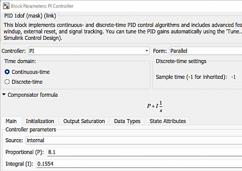
(b) Setting for PI controller
Figure 6. MATLAB simulation
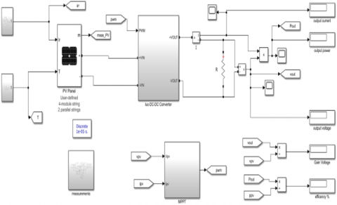
The system was tested using MATLAB/Simulink. Simulations show performance. Efficiency of the P&O MPPT with FOPI controller compared to the P&O MPPT with PI controller, P&O MPPT and IC MPPT. In Figure 7, the main design of the system is shown with the main parameters of the system.
(a) Design for all system
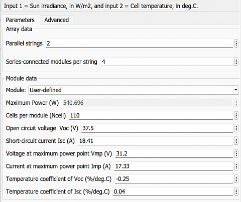
(b) Sitting for solar cell
Figure 7. MATLAB/Simulink
3.1 Positive Output Super Lift Luo Converter (POSLC)
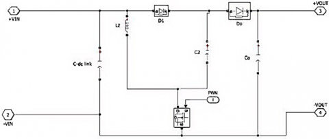
Luo Super Positive Converters are one of the best DC/DC converters due to their many advantages. The Luo ultra-thin transformer has a high voltage step-up ratio, geometric progression and a MOSFET switch connected in the low-side position. As is known, the performance of all DC-DC converters depends on cutting the input voltage through an electronic switch. The switch operates in on and off states. When on, diode D1 is forward biased and diode Do is reverse biased. The inductor (L) and capacitor (Co) store energy in parallel, and the inductor and capacitor voltages are equal to the input voltage. In the OFF state, diode D1 is reverse biased, and diode Do is forward biased. Discharge power path of inductor (L) and capacitor (Co) with series supply to the load. Figure 8 shows MATLAB/Simulink design for Positive Output Super Lift Luo Converter (POSLC) and Figure 9 shows setting system design for Luo Converter.
Figure 8. MATLAB/Simulink design for POSLC
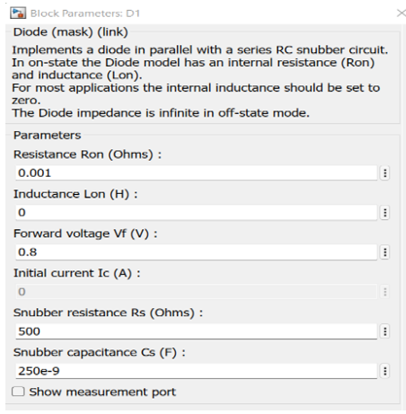
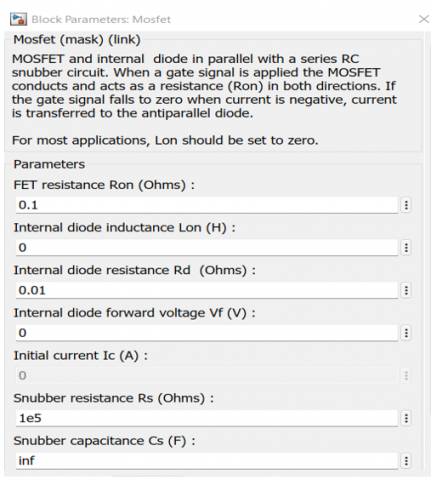
(a) Diode D1
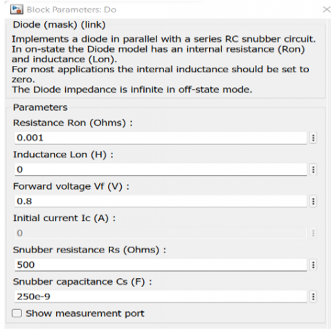
(b) Diode Do
(c) MOSFET
Figure 9. Setting system design for Luo Converter
The setting parameters of DC-DC link is 2000e-6 F, L2 is 0.1e-3 H, C2 is 10e-6 F, Co is 470e-6 F and in Figure 9, the remaining parameters of the converter are set.
3.2 Adaptive P&O MPPT with FOPI
The adaptive Perturb and Observe (P&O) MPPT algorithm with fractional order proportional-integral (FOPI) control is a novel approach designed for optimizing the power output of renewable energy systems, such as photovoltaic (PV) systems. This algorithm aims to enhance the conventional P&O method by incorporating fractional order control techniques to improve tracking accuracy and overall system performance. The key innovation lies in the integration of fractional order proportional-integral (FOPI) control within the MPPT algorithm. Unlike traditional integer-order control, FOPI introduces fractional exponents in proportional and integral terms. This allows for more flexibility and adaptability in controlling the system dynamics, providing advantages in terms of response time, stability, and robustness. The algorithm retains the basic P&O structure but modifies the perturbation and observation strategies. FOPI control enables a more nuanced adjustment of perturbation size, allowing the algorithm to navigate the power-voltage curve with greater precision, especially under dynamic environmental conditions. In contrast to conventional P&O, the FOPI algorithm dynamically adjusts the fractional order parameters based on the system's operating conditions. This adaptability enhances the algorithm's ability to handle varying environmental factors and improves overall tracking efficiency. The fractional order control enables finer adjustments to the operating point, leading to improved accuracy in tracking the maximum power point, even in the presence of partial shading or rapidly changing irradiance. The adaptability of the FOPI control contributes to faster response times, allowing the algorithm to quickly adapt to changes in the power-voltage characteristics of the renewable energy source. The fractional order control enhances system stability by providing better damping characteristics, reducing overshooting, and mitigating the effects of noise in the system.
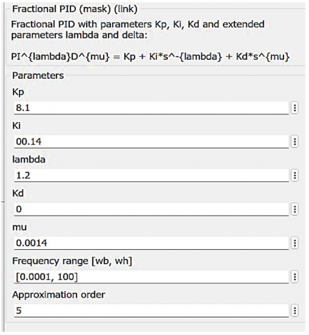
(a) Design of FOPI controller
(b) Setting of FPI controller
Figure 10. MATLAB/Simulink design of FOPI controller
Highlight improvements in terms of efficiency, convergence speed, and robustness under different operating conditions. Tuning fractional order proportional-integral (FOPI) parameters using BWO is a strategy aimed at optimizing the performance of control systems, particularly in applications like adaptive control algorithms for renewable energy systems. Here's a detailed description of the process. The goal of tuning FOPI parameters using BWO is to find optimal fractional order values for the proportional and integral components that maximize the performance of the control system. BWO, inspired by the behavior of beluga whales in nature, to efficiently search the parameter space and discover the best set of fractional-order parameters. The tuned FOPI parameters obtained through BWO optimization result in a control system with enhanced stability, faster response times, and better tracking accuracy in Figure 10.
In order to interest all the power generated by the PV panel, we must control the inverter with maximum power point tracking point. We will compare traditional MPPT methods with modified methods to extract the greatest power from PV system for Irradiation 1000 (W/M2) and Temperature 25℃.
4.1 Result with P&O MPPT
From Figure 11, we get the current PV system is 33.7A, voltage PV system is 126.5V and power PV system is 4300W. By using eight solar cells with a total capacity of 4325 watts, we find that this algorithm tracks the highest maximum power, which is 4300, with constant radiation and temperature, but this is not the power required in order to obtain higher efficiency, and this algorithm shows relatively high overshoot and ripple compared to the improved algorithm.
Figure 11. P&O MPPT
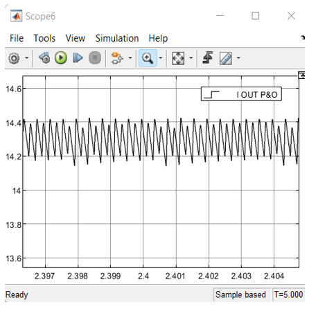
(a) Output current
(b) Output power
(c) Output voltage
Figure 12. Output system for P&O MPPT
In Figure 12, we find that the average power output is 4043W, output voltage 280V, the output current is 14.3A, the efficiency is 94.02%, and the gain voltage between input and output is 2.24.
4.2 Result with IC MPPT
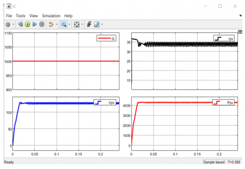
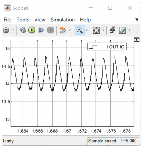
In Figure 13, we get the current PV system is 34A, voltage PV system is 123.75V and power PV system is 4308W. The results of this algorithm are better than the P&O in terms of power, ripple, and overshoot, as shown in Figure 13, and it tracks the maximum power point better. In Figure 14, we find that the average power output is 4114W, output voltage 285V, the output current is 14.35A, the efficiency is 95.5%, and the gain voltage between input and output is 2.261.
Figure 13. IC MPPT
(a) Output current
(b) Output power
(c) Output voltage
Figure 14. Output system for IC MPPT
4.3 Result P&O MPPT with adaptive PI
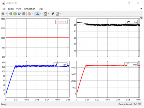
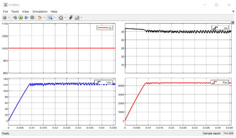
In Figure 15 we get the current PV system is 34.2A, voltage PV system is 126.3V and power PV system is 4312W. By adapting the P&O to the PI controller by adjusting its parameters with the beluga whale optimization algorithm, we find that the efficiency is higher than the two traditional theories because by integrating the two, the control system can benefit from the adaptability of the PI controller to mitigate the P&O constraints, such as oscillations around the MPP.
Figure 15. P&O MPPT with PI
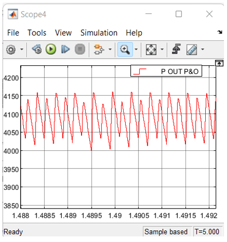
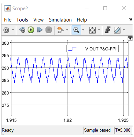
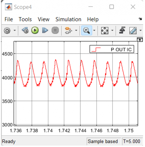
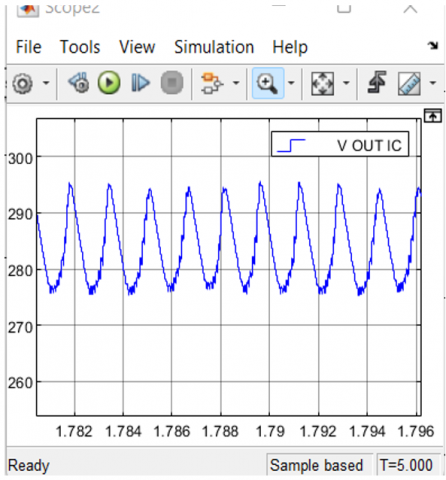
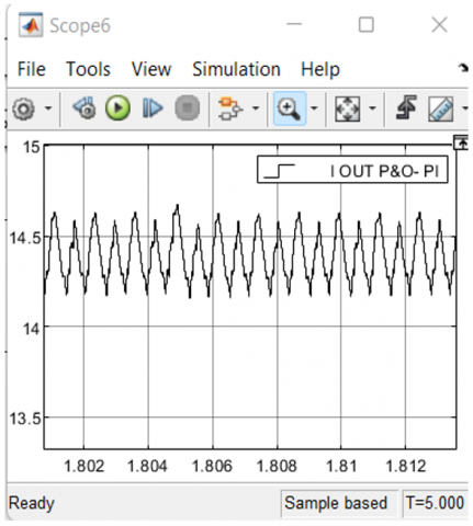
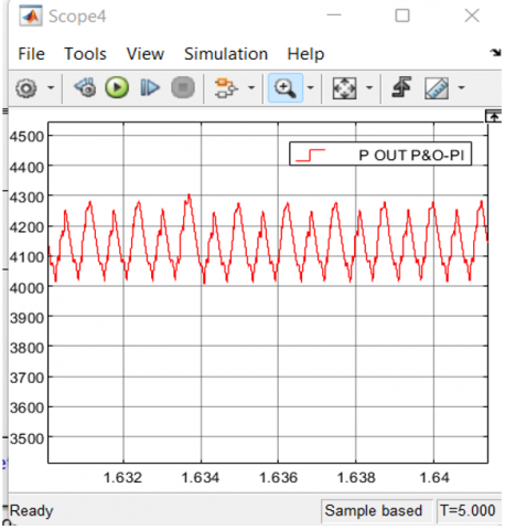
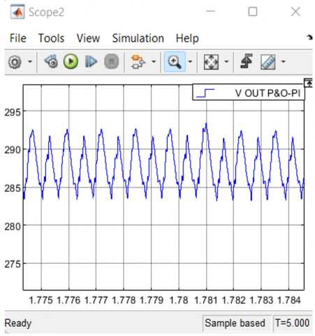
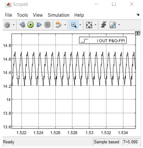
From Figure 16, we find that the efficiency is 96.12%, the average power output is 4146W, output voltage 287V, the output current is 14.4A and the gain voltage between input and output is 2.322.
(a) Output current
(b) Output power
(c) Output voltage
Figure 16. Output system for P&O-PI MPPT
4.4 Result P&O MPPT with adaptive FPI
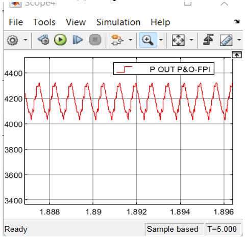
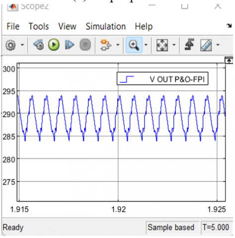
In Figure 17 we get the current PV system is 35.09A, voltage PV system is 123.5V and power PV system is 4315W. By presenting the simulation or experimental results that show the performance of the adaptive P&O MPPT with FOPI compared to the adaptive P&O MPPT with PI algorithm, the conventional P&O algorithm, and the conventional IC algorithm, it is shown that the improved algorithm using the FOPI is better in terms of efficiency and voltage gain because it controls the fractional order of the proportional integral. It improves system stability by providing better damping properties, reducing overshoot, and mitigating noise effects in the system. Efficiency is calculated by the average output power divided by the power of the solar cells entering the Luo converter, followed by MPPT algorithms. The voltage gain was calculated through the ratio of the output voltage to the input voltage of the transformer, calculated or followed by the MPPT system.
From Figure 18, we find that the efficiency is 97.05%, the average power output is 4188W, output voltage 290V, the output current is 14.56A and the gain voltage between input and output is 2.348. In Table 1 shows the simulation results between traditional and improved algorithms in detail.
Figure 17. P&O MPPT with FPI
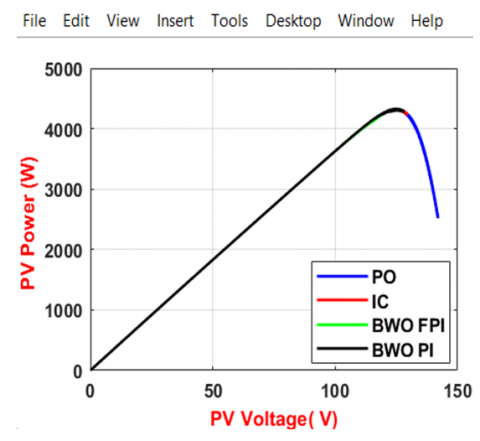
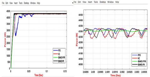
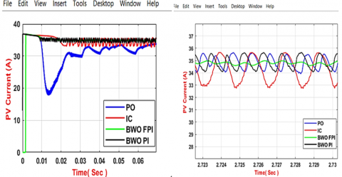
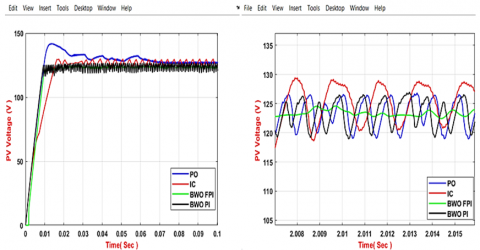
Figure 19 shows the tracking process for the maximum power output from solar cells. Figure 20 indicates the comparison or difference between the energy waves produced by MPPT methods in terms of the value of the resulting power in relation to the power coming out of the solar system, ripple, and oscillation. We notice in Figure 20(a) that we obtain the lowest ripple in power through the FOPI method or algorithm adapted to the P&O, and this indicates the speed of accuracy in tracking the maximum power point and improving the fluctuations of the P&O algorithm. We point out that the hybrid FOPI controller method is the best method compared to the rest of the methods, as its efficiency reached 97.05%, and this is considered a step forward. Good for tracking maximum power points.
(a) Output current
(b) Output power
(c) Output voltage
Figure 18. Output system for P&O-PI MPPT (a), (b), (c)
Table 1. Table results of MPPT methods from MATLAB
|
Parameter |
P&O |
IC |
P&O with PI |
P&O with FPI |
|
Temp ℃ |
25 |
25 |
25 |
25 |
|
Irradiation W/m2 |
1000 |
1000 |
1000 |
1000 |
|
PV Voltage V |
126.5 |
123.75 |
123.75 |
123.5 |
|
PV Current A |
33.7 |
34 |
34.2 |
35.09 |
|
PV Power W |
4300 |
4308 |
4312 |
4315 |
|
Output voltage V |
282.2 |
287.15 |
288 |
290 |
|
Output current A |
14.31 |
14.35 |
14.42 |
14.56 |
|
Output power W |
4043 |
4114 |
4146 |
4188 |
|
Efficiency % |
94.02 |
95.5 |
96.12 |
97.05 |
|
Gain |
2.241 |
2.261 |
2.322 |
2.348 |
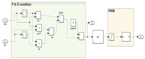
Figure 19. Sign of the dP/dV at different positions on the power characteristic
(a) Power output
(b) PV current
(c) PV voltage
Figure 20. Difference Output between algorithms MPPT
In conclusion, the adaptation of the FOPI algorithm to P&O in solar cells, coupled with the optimization of FOPI parameters using the BWO algorithm, represents a significant advancement in the field of solar energy harvesting and control. The synergy between FOPI and P&O provides a robust framework for efficient MPPT, crucial for enhancing the overall performance of solar photovoltaic systems. The utilization of the BWO algorithm for fine-tuning the FOPI parameters demonstrates the potential for harnessing the power of nature-inspired optimization techniques to achieve optimal control strategies. This hybrid approach not only enhances the accuracy and speed of MPPT but also exhibits resilience in dealing with dynamic and unpredictable environmental conditions. The successful integration of FOPI and BWO addresses some of the traditional challenges associated with conventional MPPT methods, such as sensitivity to parameter variations and oscillations around the maximum power point. By adapting FOPI to P&O and optimizing its parameters, the proposed algorithm offers improved tracking efficiency and increased energy yield, contributing to the overall viability and sustainability of solar energy systems. In summary, the FOPI algorithm adapted to P&O with parameter adjustment through the BWO algorithm showcases a promising avenue for advancing MPPT techniques in solar cells. Further research and practical implementations are warranted to validate its performance across different environmental conditions and to explore its applicability in real-world solar energy systems. The limitations of using adaptive fractional PI controller and an MPPT algorithm will result in a slight increase in system complexity and cost.
Improving design of DC-DC Luo converter using adaptive PI MPPT and IC MPPT to keep power and voltage always suitable to the user.
Future work in the field of adaptive PI MPPT and IC MPPT for the DC-DC Luo converter should focus on addressing specific challenges and exploring avenues that have the potential to bring about tangible advancements in solar energy systems. The expected outcomes of this future work include not only advancements in the control strategies for DC-DC Luo converters but also practical insights that can be directly applied to enhance the performance and efficiency of solar energy systems. Exploring these specific avenues will contribute to the broader goals of improving renewable energy harvesting technologies, making them more reliable, adaptive, and suitable for a wide range of applications.
| $I_m$ | Maximum current |
| $V_m$ | Maximum voltage |
| $P_m$ | Maximum power |
| G | Gain |
| $I_{PV}$ | Photovoltaic current |
| $I_{RS}$ | Cell's reverse saturation current |
[1] Mahmud, N., Zahedi, A. (2016). Review of control strategies for voltage regulation of the smart distribution network with high penetration of renewable distributed generation. Renewable and Sustainable Energy Reviews, 64: 582-595. https://doi.org/10.1016/j.rser.2016.06.030
[2] Liu, C., Wu, B., Cheung, R. (2004). Advanced algorithm for MPPT control of photovoltaic systems. In Canadian Solar Buildings Conference, Montreal.
[3] Salas, V., Olias, E., Lazaro, A. Barrado, A. (2005). Evaluation of a new maximum power point tracker (MPPT) applied to the photovoltaic stand-alone systems. Solar Energy Materials and Solar Cells, 87(1-4): 807-815. https://doi.org/10.1016/j.solmat.2004.07.053
[4] Karami, N., Moubayed, N., Outbib, R. (2017). General review and classification of different MPPT Techniques. Renewable and Sustainable Energy Reviews, 68: 1-18. https://doi.org/10.1016/j.rser.2016.09.132
[5] Anil, G., Murugan, N., Ubaid, M. (2013). PI controller based MPPT for a PV system. IOSR Journal of Electrical and Electronics Engineering, 6(5): 10-15.
[6] Calvinho, G., Pombo, J., Mariano, S., do Rosario Calado, M. (2018). Design and implementation of MPPT system based on PSO algorithm. In 2018 International Conference on Intelligent Systems (IS), Funchal, Portugal, pp. 733-738. https://doi.org/10.1109/IS.2018.8710479
[7] Amara, K., Fekik, A., Hocine, D., Bakir, M.L., Bourennane, E.B., Malek, T.A., Malek, A. (2018). Improved performance of a PV solar panel with adaptive neuro fuzzy inference system ANFIS based MPPT. In 2018 7th International Conference on Renewable Energy Research and Applications (ICRERA), Paris, France, pp. 1098-1101. https://doi.org/10.1109/ICRERA.2018.8566818
[8] Mahdi, A.S., Mahamad, A.K., Saon, S., Tuwoso, T., Elmunsyah, H., Mudjanarko, S. W. (2020). Maximum power point tracking using perturb and observe, fuzzy logic and ANFIS. SN Applied Sciences, 2: 89. https://doi.org/10.1007/s42452-019-1886-1
[9] Abderrahim, Z., Eddine, H.K., Sabir, M. (2021). A new improved variable step size MPPT method for photovoltaic systems using grey wolf and whale optimization technique based PID controller. Journal Européen des Systèmes Automatisés, 54(1): 175-185. https://doi.org/10.18280/jesa.540120
[10] Mohammed, S.S., Devaraj, D. (2014). Simulation and analysis of stand-alone photovoltaic system with boost converter using MATLAB/Simulink. In 2014 International Conference on Circuits, Power and Computing Technologies [ICCPCT-2014], Nagercoil, India, pp. 814-821. https://doi.org/10.1109/ICCPCT.2014.7054991
[11] Hussein, H.A.K., Motlak, H.J. (2022). Improving the design of super-lift Luo converter using hybrid switching capacitor-inductor cell for PV system. Indonesian Journal of Electrical Engineering and Computer Science, 25(2): 710-720. https://doi.org/10.11591/ijeecs.v25.i2.pp710-720
[12] Sharma, H., Pal, N., Sadhu, P.K. (2015). Modeling and simulation of off-grid power generation system using photovoltaic. TELKOMNIKA Indonesian Journal of Electrical Engineering, 13(3): 418-424. http://doi.org/10.11591/telkomnika.v13i3.7061
[13] Messenger, R.A., Abtahi, A. (2018). Photovoltaic systems engineering. CRC press.
[14] De Soto, W., Klein, S.A., Beckman, W.A. (2006). Improvement and validation of a model for photovoltaic array performance. Solar energy, 80(1): 78-88. https://doi.org/10.1016/j.solener.2005.06.010
[15] Jiang, Y., Qahouq, J.A.A., Batarseh, I. (2010). Improved solar PV cell Matlab simulation model and comparison. In 2010 IEEE international symposium on circuits and systems (ISCAS), Paris, France, pp. 2770-2773. https://doi.org/10.1109/ISCAS.2010.5537014
[16] Walker, G. (2001). Evaluating MPPT converter topologies using a MATLAB PV model. Journal of Electrical & Electronics Engineering, Australia, 21(1): 49-55.
[17] Motlak, H.J., Rahi, A.S. (2020). Performance comparison of different control strategies for the regulation of DC-DC negative output super-lift luo-converter. International Journal of Electrical & Computer Engineering, 10(6): 5785-5792. http://doi.org/10.11591/ijece.v10i6.pp5785-5792
[18] Luo, F.L., Ye, H. (2018). Essential DC/DC Converters. CRC Press.
[19] Khalil, H.K., Hreshee, S.S., Motlak, H.J. (2020). Design and implementation of photovoltaic system based on super-lift LUO converter. Journal of Physics: Conference Series, 1530: 012013. http://doi.org/10.1088/1742-6596/1530/1/012013
[20] Kabala, M. (2017). Application of distributed DC/DC electronics in photovoltaic systems. Doctoral dissertation, Colorado State University.
[21] Owusu-Nyarko, I., Elgenedy, M.A., Abdelsalam, I., Ahmed, K.H. (2021). Modified variable step-size incremental conductance MPPT technique for photovoltaic systems. Electronics, 10(19): 2331. https://doi.org/10.3390/electronics10192331
[22] Dhinesh, V., Vijayakumar, D.G., Saravanan, D.S. (2020). A photovoltaic modeling module with different converters for grid operations. International Journal of Innovative Research in Technology, 6(8): 89-95.
[23] Sahoo, J., Samanta, S., Bhattacharyya, S. (2020). Adaptive PID controller with P&O MPPT algorithm for photovoltaic system. IETE Journal of research, 66(4): 442-453. https://doi.org/10.1080/03772063.2018.1497552
[24] Zhong, C., Li, G., Meng, Z. (2022). Beluga whale optimization: A novel nature-inspired metaheuristic algorithm. Knowledge-Based Systems, 251: 109215. https://doi.org/10.1016/j.knosys.2022.109215