Oussama Belaroussi*![]() | Amel Terki
| Amel Terki![]() | Ilyes Dahnoun
| Ilyes Dahnoun![]() | Ahmed Lechelah
| Ahmed Lechelah![]()
© 2024 The authors. This article is published by IIETA and is licensed under the CC BY 4.0 license (http://creativecommons.org/licenses/by/4.0/).
OPEN ACCESS
Photovoltaic (PV) water pumping systems address water accessibility challenges in isolated regions by offering sustainable, self-sufficient solutions that do not rely on the power grid. These systems provide enduring advantages, such as reduced operational expenses, while also making a substantial contribution to agricultural progress and enhancing the quality of life in rural areas. The utilization of solar energy for powering rural areas has been significantly reduced due to recent technological breakthroughs. The objective of this study was to utilize MATLAB-Simulink models to simulate a photovoltaic water pumping system and generate an ideal direct current (DC) voltage at the input of the inverter. In addition, the machine side utilizes space vector modulation (DTC-SVM), while the DC voltage side employs fuzzy logic control (FLC). The fuzzy logic methodology is highly effective in dealing with non-linear and complicated systems, providing strong control in situations where conventional methods may face difficulties. DTC-SVM improves the management of motors by providing superior dynamic performance, minimizing torque fluctuations, and increasing overall efficiency. This makes it a highly valuable technique for motor control systems. When the DTC-SVM method is applied to the induction motor instead of the field-oriented control (FOC) and conventional direct torque control (DTC), it was discovered that the centrifugal pump exhibits a more rapid dynamic reaction and performs more effectively.
photovoltaic energy, direct torque control, boost converter, fuzzy logic controller, induction motor feeds the pump
Sustainable development has become the concern of the current generation and the new horizon for researchers, which represents the main benefits of the electrical system based on renewable energy always stock sources and fixed rates [1]. Of all the renewable energy sources, the photovoltaic (PV) system is the most widely utilized worldwide. This is because it has a long lifespan, low maintenance expenses, great dependability, and can harness sun energy in any location on the planet. PV systems harness solar energy by directly converting it into direct current (DC) electrical power through the utilization of semiconductor characteristics. These devices have the capability to function independently (off-grid), connect to the power grid, or operate in a combination of both modes. Standalone mode is employed to generate power in rural and remote regions that are inaccessible by the electrical grid or where the expense of connecting to the grid is prohibitive (known as islanded operation) [2]. More recently, the applications of photovoltaic energy have become more prevalent and more popular outside the network, particularly in water pumping systems. The water pumping system is a widely utilized application in the generation of renewable energy. This application is utilized in remote regions, typically isolated mountainous or rural locations, where access to a power grid is unavailable. Populations frequently employ the PV pumping system to meet their home water needs and for agriculture purposes.
In an experiment to increase efficiency and reduce the cost of systems used and improve the performance and reliability of the PV energy pumping system [3]. Usage depends on two types of independent PV systems: the first is to store surplus energy of photovoltaic energy in batteries, thereby increasing the cost of the system by 10–50%. The second is without using batteries, and in this, the water is stored in reservoirs [4]. For example, diesel engines are used as pumps for agriculture in isolated areas for ease of installation and because of the bad choice considered These types of systems cause a lot of environmental problems because of their work, which depends on fossil energy [5]. Moreover, the frequent repairs and maintenance of diesel pumps are generally 2–4 times more frequent than pumps based on PV energy [6]. Accordingly, water pumps based on renewable energy offer an alternative solution. Induction motor PV pumping systems are frequently used because they are more reliable and cost-effective, and they do not require ongoing maintenance [7].
Nevertheless, in such systems, it is imperative to accurately and efficiently manage the energy generated by solar panels to the fullest extent possible. To enhance the efficiency of solar panels, it is necessary to optimize the DC voltage control provided by them. Various control solutions have been found in the literature to accurately follow the maximum power point tracking (MPPT) for the photovoltaic array [8]. Since most of these solutions can achieve the same goals, they work very quickly and efficiently even when conditions like temperature and irradiation change, even though they use different principles. One of the primary tactics employed is the standard P&O technology, renowned for its flexibility and simplicity, making it the most prevalent commercial product. However, the dynamic reaction of the system remains poor due to the need for a comprehensive understanding of the model, which directly impacts the efficiency of the PV pumping system. As a consequence of this drawback, we present in this study an alternative MPPT technology that is based on a novel intelligent control system known as fuzzy logic. This control offers the benefit of being a potent and relatively uncomplicated tool in development without necessitating an extensive understanding of the model to be employed [9].
IM (inverter module)-based PV water pumping systems are divided into two typical configurations [10]: the first model is a dual-stage water pumping system, which consists of a PV panel and DC-DC converter to boost the voltage array obtained from the PV panel and maximize energy, and a DC-AC inverter to convert voltage to alternating voltage, which feeds the pump paid by IM. This model is considered an easy model and simpler in terms of control, taking into account the increase in the number of its components.
The second model is a water pumping system with a single-stage which doesn't consist of a DC-DC converter, so that the DC-AC inverter works with a tracking algorithm that allows it to perform the function of the DC-DC converter. At the same time, it converts the voltage to an alternating voltage, to feed the pump paid by IM, with the imposition of connecting the solar panels in sequential order [11].
On the other hand, the solar panel water pumping system is being improved by improving the control method of the IM. Many researchers proposed various strategies for controlling IM in this regard [12]. In many years, much research has been done that aims to address and improve optimal IM control and develop strong and effective controls for it. Naturally, optimum IM control increases pump flow.
Field-oriented control (FOC), often referred to as vector-based control, is a widely used strategy for managing induction motors (IM) [13]. FOC relies on the notion of utilizing two loops: one for the internal current loop, which should be responsive, and another for a robust and stable loop. The external speed should also be considered, and the response time of the rotor flow loop should be reduced [14]. FOC has been proposed as a method that highlights the benefits of having independent control over torque and flow. This concept is derived from the operation of an independently stimulated DC machine. The FOC technique has excellent dynamic performance in steady-state conditions and minimizes the presence of ripple energy. Additionally, it decreases the switching frequency of the inverter [15]. However, the drawbacks associated with this level of control deter IM users from using it. The FOC method is known to be extremely responsive to any modifications in its parameters, such as temperature. Consequently, this will result in a noticeable decline in the performance of the IM [16]. Direct torque control is a highly prevalent form of control in the IM. The DTC drive system relies on static hysteresis for controlling both flow and torque, as stated in reference [17]. This control method is selected due to its straightforward structure and excellent performance with high efficiency. However, it also introduces ripples that directly impact the efficiency of our system and the lifespan of the motor-pump unit [18]. In order to minimize undulations and prevent deformation in fluid motion. In this research, we suggest utilizing DTC with a space vector modulation method (DTC-SVM) as a solution to mitigate the ripples commonly encountered in conventional DTC [19].
Our objective is to enhance the control approaches employed for the inverter module in a solar-powered water pumping system by optimizing its efficiency. The implementation of this system utilizes the simulation program Simulink-MATLAB R2018a.
The paper is structured as follows: after the introduction, we provide the background information. In the second portion, we conduct a comprehensive examination of the system components, focusing on the modeling of each individual piece. In the third section, we thoroughly examine the suggested control techniques for this particular system. In the fourth segment, we evaluate the outcomes of the system simulation and its analysis. In the fifth part, we will examine the summary and findings of this study.
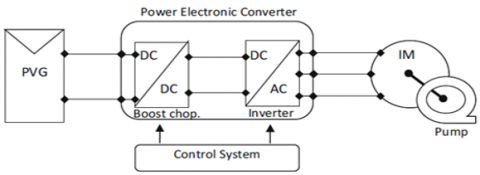
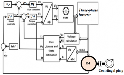
Figure 1 illustrates the structure of the proposed solar photovoltaic (SPV) array-powered water pumping system, which uses an induction motor and a DC-DC converter. The suggested system comprises, in sequential order, a solar photovoltaic (SPV) array, a DC to DC converter, a three-phase inverter, an induction motor, and a centrifugal water pump.
Figure 1. Configuration of solar-powered water pumping system
2.1 Photovoltaic generator modeling
The PV generator comprises a photovoltaic cell that converts solar energy, in the form of radiation, into an electric current. This cell is often fabricated using a thin layer of silicon. The solar panel's input parameters consist of irradiance, which is measured in watts per square meter (W/m2), and temperature, which is measured in degrees Celsius (℃).
The PV generator consists of a photocurrent source, a diode, and both series and shunt resistances [20]. The attributes of the photovoltaic generator may be expressed as follows:
$\begin{gathered}I_{p v}=I_L-I_0\left[\exp \left(\frac{V_{p v}+R_s I_{p v}}{V_{t h}}\right)-1\right] -\frac{\left(V_{p v}+R_s I_{p v}\right)}{R_{s h}}\end{gathered}$ (1)
where: $I_{p v}$, $R_{s h}$ and $R_s$ Indicate the current output of the array, the equivalent shunt resistance of the PV array, and the series resistance of the PV array, in that order. The symbol $I_L$ represents the thermal voltage of the PV array, as defined by Eq. (2). The photo-current, denoted as $I_0$, is created based on the Eq. (3). The reverse saturation current of the PV array, denoted as $I_0$, is determined by Eq. (4). The short circuit current of the PV array, denoted as $I_{s c}$, is defined by Eq. (5).
$V_{t h}=\frac{\left(V_{m p}+R_s I_{m p}-V_{o c}\right)}{\log \left(1-\frac{I_{m p}}{I_{s c}}\right)}$ (2)
$I_L=\left(I_{s c}+K_i(T-298.15)\right) \frac{G}{1000}$ (3)
$I_0=\left(I_{s c}-I_{m p}\right) \exp \left(\frac{\left(V_{m p}+R_s I_{m p}\right)}{V_{t h}}\right)$ (4)
$I_{s c}=I_{s c_R} \frac{G}{G_R}\left[1+\alpha\left(T_{c e l}-T_{c e l_R}\right)\right]$ (5)
2.2 Boost converter
The primary function of the DC-DC power converter is to control and modify the voltage output from the PV array in order to enhance the amplification of solar energy. A boost converter is a basic power circuit that comprises an inductor, a capacitor, two diodes, and a switching component. The most often used component in this circuit is the bipolar transistor, specifically the insulated-gate bipolar transistor (IGBT). Considering that the input capacitor filter may be eliminated to simplify the design process of the MPPT controller, it can be equated to the output current of the PV system together with the inductor current.
The continuous model of the DC-DC boost converter is constructed as follows:
$\left\{\begin{array}{c}\frac{d I_{p v}}{d t}=\frac{V_{p v}-V_{\text {out }}}{L}(1-D) \\ \frac{d V_{\text {out }}}{d t}=\frac{I_{p v}}{C}-\frac{V_{\text {out }}}{R C}(1-D)\end{array}\right.$ (6)
The boost converter model may be formed in two scenarios based on the switch's states, namely On and Off. The attention is mostly on continuous conduction. The formulation of the Boost converter changes depending on its structure.
2.3 Three-phase inverter
The inclusion of a boost converter, which is responsible for voltage adjustment and enhancement, is inadequate for powering the induction machine in this particular system. Hence, in the photovoltaic system, it is essential to use an inverter to effectively and securely interface with the induction machine, guaranteeing energy management by converting the DC output voltage from the transformer into regulated alternating voltage. A voltage source inverter (VSI) is often used for this objective. The potential use of a current source inverter (CSI) is of great importance in the realm of solar energy conversion from direct current to alternating current, particularly in three-phase current inverters. This utilization guarantees the production of a well-balanced three-phase power system. The functioning of the inverter is contingent upon the state of the switches [21]. The voltage system may be expressed as the following matrix:
$\left[\begin{array}{l}V_1 \\ V_2 \\ V_3\end{array}\right]=\frac{V_{p v}}{3}\left[\begin{array}{ccc}2 & -1 & -1 \\ -1 & 2 & -1 \\ -1 & -1 & 2\end{array}\right]\left[\begin{array}{l}K_1 \\ K_2 \\ K_3\end{array}\right]$ (7)
The equation presented demonstrates the continuous functioning of a DC source:
$I_{p v}=K_1 I_{s a}+K_2 I_{s b}+K_3 I_{s c}$ (8)
2.4 Mathematical modeling of the induction motor
The dynamic characteristics of a three-phase induction motor in the (d, q) reference frame may be explained as follows: the stator voltage is generated inside the d-q coordinate system:
$V_{d s}=R_s I_{d s}+\frac{d}{d t} \emptyset_{d s}$ (9)
$V_{q s}=R_s I_{q s}+\frac{d}{d t} \emptyset_{q s}$ (10)
The rotor voltage isformed in d-q coordinate system as:
$0=V_{d r}=R_r I_{d r}+\frac{d}{d t} \emptyset_{d r}+\omega_m \emptyset_{q r}$ (11)
$0=V_{q r}=R_r I_{q r}+\frac{d}{d t} \emptyset_{q r}+\omega_m \emptyset_{d r}$ (12)
The stator flux is formed in d-q coordinate system as:
$\emptyset_{d s}=l_s I_{d s}+M I_{d r}$ (13)
$\emptyset_{q s}=l_s I_{q s}+M I_{q r}$ (14)
The rotor flux is formed in d-q coordinate system:
$\emptyset_{d r}=l_r I_{d r}+M I_{d c}$ (15)
$\emptyset_{q r}=l_r I_{q r}+M I_{q s}$ (16)
and the electromagnetic torque is formed:
$C_{e m}=\frac{P M}{l_r}\left(\emptyset_{d s} I_{q s}-\emptyset_{q s} I_{d s}\right)$ (17)
where: ls represent the stator inductance and lr represent also the rotor inductance, Rs, Rr and M symbolize stator resistance, rotor resistance and mutual inductance of IM respectively. Is, Ir denote the stator and rotor current is formed in d-q coordinate system, $\omega_{\mathrm{m}}$ is the rotor electrical frequency in rad/s [22].
2.5 Modeling of centrifugal pump
Multiple pumps are used in water pumping systems that make use of photovoltaics, recognizing that this is a vital component of the system. Centrifugal pumps are the optimal choice for handling large flow rates and high total head requirements, while maintaining a high level of efficiency [23]. The pump's attributes may be represented using the following mathematical model:
$P=\frac{\rho g H Q}{\eta}$ (18)
$\eta=\frac{P u}{P}$ (19)
And torque-speed equation is given by the following expression:
$\begin{gathered}T_{\text {pump }}=K_1 w^2+K_2 w Q+K_3 Q^2 \\ T_r=A w_r{ }^2 \\ A=P_n / w_n{ }^3\end{gathered}$ (20)
where:
N→ the rotational speed shaft of pump given by (rad/s), $\rho$ → volumetric water mass given by (Kg/ $\mathrm{m}^3$). Q → the water flow ($\mathrm{m}^3$/s), and H → the height of rise (m), g → the acceleration of gravity ($\mathrm{m}^2$/s). $K_1$, $K_2$, $K_3$ → are coefficients given by the manufacturer [24].
$w_r$: Motor speed; $P_n$: Nominal hydraulic power of the pump; $w_n$: Nominal speed of the pump.
A feed-forward equation for speed derived from solar power's available power is as follows:
$w_r^*=K \sqrt[3]{P_{p v}}$ (21)
where, $P_{p v}$ is photovoltaic power and K=1/ $\sqrt[3]{A}$. This feed-forward speed increases the dynamic performance in standalone mode and decreases the system's dependence on the pump's consistent accuracy [25].
3.1 Fuzzy logic control
The utilization of this technique, originally suggested by Lotfi Zadeh in 1965, has become a viable substitute for many control systems in recent times. Fuzzy logic approaches have shown to be useful in several sectors and are applied in virtually every field. The fuzzy logic structure consists of three sub-blocks: fuzzification, inference, and defuzzification, as shown in Figure 2 [26].
Figure 2. An overview of the FLC's structure
· Identification of input and output variables and their fuzzification.
The fuzzy logic MPPT algorithm incorporates measurements of voltage and current at each moment k to ascertain the active power. The power change (DP(k)) is determined by comparing the current active power to the power at the prior time K-1. In order to determine the voltage error (DV(k)), the voltage at time k was compared to the voltage at time K-1. To compute the change in error De(k), the power error is divided by the voltage error to generate the error e. This error e is then compared with the prior error to determine the change in error De(k), as shown in the following equation:
$\left\{\begin{array}{c}e(k)=\frac{P(k)-P(k-1)}{V(k)-V(k-1)} \\ \Delta e(k)=e(k)-e(k-1)\end{array}\right.$ (22)
Ke, Kde, and Kc are crucial scaling parameters for FLC design, ensuring a favorable response in dynamic and transient scenarios. They can be either constants or variables [27].
A. Fuzzification
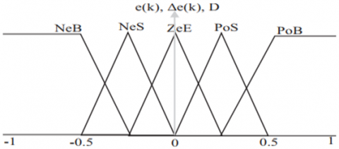
During this stage, the numerical input variables (e(k) and Δe(k)) are transformed into linguistic variables by the utilization of a membership function. This transformation encompasses seven gradations of imprecision represented as ZeE (Zero), PoB (Positive Big), PoS (Positive Small), NeB (Negative Big), and NeS (Negative Small). Figure 3 vividly depicts these stages.
Figure 3. The FLC's variable linguistics membership functions
B. Fuzzy Rule Base
Below is a table that presents 25 inference rules for different combinations of linguistic variables e(k) and Δe(k), resulting in the output D. The IF-THEN rules exemplify the fuzzy correlation between the input variables and the output variables, and may be classified into the following categories:
*IF [e(k) is NeB] and [Δe(k) is NeB] THEN [D is ZeE]; If both the error (e(k)) and the change in error (Δe(k)) are evaluated as having the linguistic value 'Negative Big', then the duty cycle (D) for the control action should be adjusted to 'Zero' (ZeE).
*IF [e(k) is PoB] and [Δe(k) is NeB] THEN [D is PoB]; If the error signal e(k) is classified as "Positive Big" and the rate of change of the error Δe(k) is classified as "Negative Big", then the duty cycle D is classified as "Positive Big" (Table 1).
Table 1. Rule base of FLC with the inputs E and $\Delta$E and the output $\Delta$D
|
Δe(k)/e(k) |
NeB |
NeS |
ZeE |
PoS |
PoB |
|
NeB |
ZeE |
ZeE |
NeS |
PoS |
PoB |
|
NeS |
ZeE |
ZeE |
ZeE |
PoS |
PoB |
|
ZeE |
NeB |
NeS |
ZeE |
PoS |
PoB |
|
PoS |
NeB |
NeS |
ZeE |
ZeE |
ZeE |
|
PoB |
NeB |
NeS |
PoS |
ZeE |
ZeE |
C. Inference and Defuzzification
This approach constructs the combination of the outputs of each rule, resulting in the conversion of the inferred fuzzy control action into a numerical variable at the output, as specified by Eq. (23).
$\overline{M_n}=\frac{\overline{\sum_{l=1}^N \mu_l D_l}}{\sum_{i-1}^N \mu_i}$ (23)
where,
N: Quantity of rules.
$\mu_i$: Denotes the hierarchical position within the membership.
$D_i$: The coordinate associated with the corresponding output.
3.2 The control strategies of the inverter
3.2.1 Sinusoidal Pulse Width Modulation (SPWM)
The primary function of the inverter is to transform the power output from the converter into a sinusoidal waveform, achieved through the use of a MOSFET/IGBT switch. Sinusoidal Pulse Width Modulation (SPWM) is a widely utilized technique for this procedure. This technique is widely employed in several industrial sectors to provide motors with sinusoidal power at variable voltage and frequency levels. In this study, we employ this strategy to generate a reflective output that consists of sinusoidal signals for the induction machine. SPWM is produced by comparing a sine signal with a triangle wave, also known as a sawtooth wave. This is done by intersecting a sawtooth wave with a sinusoidal wave, resulting in the generation of reference wave pulses. The width of the pulses is contingent upon the reference wave and is also influenced by the modulation index range. It is widely recognized that this approach produces pulses of varying width and magnitude, allowing the power provided to the engine to be regulated by a series of PWM control signals sent to the gates [28].
3.2.2 Hysteresis controller
This technique has several applications in transformers and motors. This technology is distinguished by its quick responsiveness and excellent unconditional stability. Additionally, it is regarded as robust and has exceptional dynamics. Additionally, it is distinguished by a broad range of instructions. This technology regulates the interphase reaction of the motor by adjusting the variable hysteresis range in response to variations in the normal load (continuous load) between phases.
The functioning of this strategy is contingent upon the examination of the mistake scenario. When the current error surpasses or reaches the upper limit, it induces a negative voltage, leading to a reduction in current. If the current error is equal to or exceeds the lower limit, a positive voltage is supplied. This results in an increase in the current [29, 30].
3.3 Proposed strategies control of the induction motor
Several scholars have suggested different ways for managing instant messaging in this context. Over the course of many years, much research has been conducted with the goal of addressing and enhancing optimum IM control, as well as developing robust and efficient controls for it. Optimal IM management naturally enhances the flow rate of the pump.
3.3.1 Flux oriented control
There are two methods accessible for flux-oriented control (FOC). The first method is referred to as indirect flux-oriented control (IFOC). Hasse made this assumption in 1968. Another approach is direct flux-oriented control (DFOC), which was proposed by Blaschke in 1972. The idea of flux-oriented control (FOC) relies on aligning the flux to get an induction motor (IM) behavior that resembles that of a DC machine. Considering the independent excitation to provide distinct control over the flow and torque. For this investigation, we choose to align the rotor flux with the direct axis of the reference point. The equations governing the IFOC command may be expressed as follows:
When we apply the law of orientation ($\varphi_{\mathrm{qr}}=0 \rightarrow \varphi_{\mathrm{dr}}=\varphi_{\mathrm{r}}$) in the plan d,q we will have:
$\left\{\begin{array}{c}\varphi_{d r}=\varphi_r=L_r I_{d r}+M I_{d s} \\ \varphi_{q r}=0=L_r I_{r q}+M I_{s q} \\ T_{e m}=-P \varphi_{d r} I_{q r}\end{array}\right.$ (24)
Which gives:
$\left\{\begin{array}{l}I_{q s}=-\frac{L_r}{M} I_{q r} \\ I_{q r}=-\frac{M}{L_r} I_{q s}\end{array}\right.$ (25)
We impose this requirement to ensure a unit power factor:
$I_{d r}=0$ (26)
From Eqs. (24), (25), and (26), we can figure out what the reference currents are. This gives us:
$\varphi_{q r}=0$, then the objectif is $I_{q s}^*=-\frac{L_r}{P M \varphi_{d r}^*}$.
$\varphi_{d r}=\varphi_r$, then the objectif is $I_{d s}^*=\frac{L_r}{M} \varphi_{d r}^*$.
$T_{e m}=T_{e m}^*$, then the objectif is $I_{q s}^*=\frac{1}{P \varphi_{d r}^*} T_{e m}^*$.
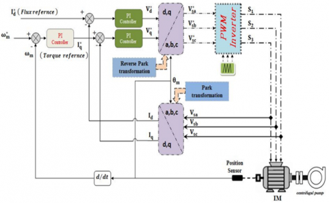
Figure 4. Block diagram of FOC of induction motor feeding a centrifugal pump
To attain the theoretical goals upon which this technology is founded, we conduct a comparison between the control's reference parameters and those of IM. This enables us to identify the inaccuracy in each parameter and then eradicate the static error. Considering the system's stability, we achieve a rapid reaction time while maintaining a clear distinction between flux and torque as showing in Figure 4 [31].
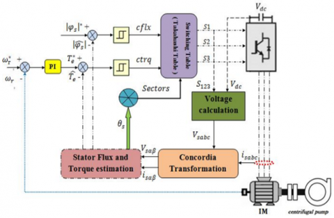
3.3.2 Control design of DTC
In the 1980s, Takahashi devised a novel control approach known as DTC (Direct Torque Control). Subsequently, Takahashi, Noguchi, and other researchers in Japan implemented and showcased this approach from 1986 to 1999. Depenbrock and others submitted it throughout the period of 1986 to 1992 [32]. An inherent benefit of this approach is in the ability to exert precise command over the electromagnetic torque and stator flux linkage by choosing from a set of eight voltage vectors used in the inverter. The selection of sequences is contingent upon torque and stator faults that fall below predetermined hysteresis limits. The DTC controller does not rely on the principle of constant current control through direct flow control. Instead, it utilizes two hysteresis comparators (flux and torque) to ensure that the torque remains within specified limits by determining the switching voltage vector [33]. This is illustrated in Figure 5.
Figure 5. Block diagram of DTC of induction motor feeding a centrifugal pump
*Flux and torque estimator:
The ultimate torque equation is contingent upon the stator variables, voltage, currents, and resistance, all of which need precise measurement. The equation for torque is expressed as:
$T_e=\left(\frac{3}{2}\right)\left(\frac{P}{2}\right) \frac{L_m}{\vartheta L_s L_r}\left|\varphi_s \| \varphi_r\right|(\sin \theta)$ (27)
where, $\vartheta=1-\frac{L_m^2}{L_s L_r}$ is the leakage factor.
By referring to Eq. (27), we may infer that the variation in torque is strongly connected to the alteration in the constant magnitudes of stator and rotor flux. This relationship is similar to the one seen between rotor and stator flux [34].
The flux stator for the stationary reference frame is given as:
$\frac{d \varphi}{d t}=V_s-\left[R_s\right] I_s$ (28)
$\varphi_s=\int V_s-\left[R_s\right] I_s$ (29)
The temporal duration plays a crucial role in this method, namely between the simultaneous occurrence of the six vectors. Only one voltage vector is used for the purpose of sampling. Thus, Eq. (29) may be restated in the following manner:
$\varphi_s=\int_0^t V_s d t-\left[R_s\right] \int_0^t I_s d t$ (30)
$\varphi_s=V_s . \Delta t+\varphi_{s / t=0}$ (31)
where, $\varphi_{s / t=0}$, the principal stator flux linkage at the moment of switching is denoted as $V_s$ and $I_s$ represents the observed stator voltage and current. Also $R_s$ refers to the estimated stator resistance. As a result of the high velocity, we disregard the decrease in resistance. The expression obtained is as follows:
$\Delta \varphi_s=V_s \Delta t$ (32)
The amplitude of the stator flux linkage may be regulated by applying a suitable voltage vector as specified in Eq. (32).
We used the frame $(\alpha, \beta)$ in our study. Hence, in the stationary frame $(\alpha, \beta)$ associated with the stator, the flux and torque relations may be expressed as:
$\left\{\begin{array}{c}\varphi_{s \alpha}=\int\left(V_{s \alpha}-R_s I_{s \alpha}\right) \\ \varphi_{s \beta}=\int\left(V_{s \beta}-R_s I_{s \beta}\right) \\ \left|\varphi_s\right|=\sqrt{\varphi_{s \alpha}^2+\varphi_{s \beta}^2}\end{array}\right.$ (33)
$T_e=\frac{3}{2} p\left(\varphi_{s \alpha} I_{s \beta}-\varphi_{s \beta} I_{s \alpha}\right)$ (34)
*Switching table:
Referring to the torque and flux hysteresis states and the stator sector described in Eq. (35). Table 2 displays the swapping or switching table that governs both the rotational direction of the bearing and the magnitude of the stator flux. The exchange table consists of six sectors of voltage vectors. Every sector consists of four voltage vectors that are not equal to zero, out of a total of six vectors. The flux sector is represented by $\theta$, whereas $\mathrm{T}^*$ and $\varphi^*$ denote the outputs of the torque and flux hysteresis comparators, respectively. In Table 2, when $\varphi^*$ = 1 (increase), the actual flux is not precisely equal to the reference value. Conversely, when $\varphi^*$ = 0 (reduction), the actual flux is greater than the reference value. This also implies the rotational force.
$\theta=\operatorname{arc}\left(\varphi_s\right)=\operatorname{arctg}\left(\frac{\varphi_{s \alpha}}{\varphi_{s \beta}}\right)$ (35)
Table 2. Switching table (TAKAHASHI table)
|
|
Sector |
||||||
|
Flux |
Torque |
1 |
2 |
3 |
4 |
5 |
6 |
|
Increase |
Increase |
V2 |
V3 |
V4 |
V5 |
V6 |
V1 |
|
No Change |
V0 |
V7 |
V0 |
V7 |
V0 |
V7 |
|
|
Decrease |
V6 |
V1 |
V2 |
V3 |
V4 |
V5 |
|
|
Decrease |
Increase |
V3 |
V4 |
V5 |
V6 |
V1 |
V2 |
|
No Change |
V7 |
V0 |
V7 |
V0 |
V7 |
V0 |
|
|
Decrease |
V5 |
V6 |
V1 |
V2 |
V3 |
V4 |
|
We can write the output voltage Vs and current VSI in the Concordia frame as follows:
$\left\{\begin{array}{c}\bar{V}_s=V_{s \alpha}+j V_{s \beta} \\ \bar{I}_s=I_{s \alpha}+j I_{s \beta} \\ \bar{V}_s=\sqrt{\frac{2}{3} V_{d c}\left(S a+S b \cdot e^{j \frac{2 \pi}{3}}+S c \cdot e^{j \frac{4 \pi}{3}}\right)}\end{array}\right.$ (36)
where: Sa, Sb and Sc are the inverter’s switches. $V_{s \alpha}$, $V_{s \beta}$, $I_{s \alpha}$ and $I_{s \beta}$ are respectively the direct and quadrature voltage and current vectors [35].
3.3.3 Direct torque control-space vector modulation (DTC-SVM)
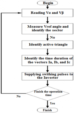
Figure 6. DTC-SVM configuration
Figure 7. Flow-chart of DTC-SVM algorithm
The conventional DTC algorithm use hysteresis comparators to regulate the torque and flux, and also considers the sector position of the instantaneous flux to calculate the appropriate switching states for the inverter. The hysteresis comparator is characterized by its significant torque and flux ripples, as well as its variable switching frequency, which are considered its basic drawbacks. Various scholars agree on integrating the benefits of Direct Torque Control and Field Oriented Control inside a unified framework to address these limitations, leading to the development of the DTC-SVM approach. The DTC-SVM method differs from the DTC method in that it utilizes average values and the SVM algorithm to estimate the switching state of an inverter, instead of relying on instantaneous measurements and direct computations. Figure 6 demonstrates the use of DTC-SVM to assess the reference voltage vector and modify it via the employment of the SVM approach, resulting in the generation of inverter switches. Figure 7 depicts the diagram of the DTC-flow SVM. This design regulates the torque and flux of an induction motor. The control methodology involves modifying the voltages generated by PI controllers. The SVM module is used to generate switching signals for the inverter. The DTC-SVM arrangement eliminates the hysteresis controllers and the look-up database, therefore mitigating the associated downsides [36].
The proposed solar energy harvesting model is simulated for a duration of two and a half seconds to establish a correlation between the transfer of the sequential pumping system and various scenarios. And by fixed temperature (25 degrees)/ varied irradiation conditions. Discrete simulation is the preferable method for achieving optimal analysis, as opposed to continuous simulation.
The boost chopper parameters employed are as follows: Input capacitor with a value of 2000μF, inductor with a value of 1mH, and output capacitor with a value of 2000μF.
The characteristics of the induction motor utilized are as follows: Rs = 6.75 Ω, Rr = 6.21 Ω, Ls = 0.5192 H, Lr = 0.5192 H, M = 0.4957 H, J = 0.0140, Fr = 0.002, P = 2.
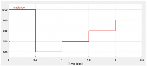
Figure 8 represent the solar shine of the photovoltaic generator, which we used in this work.
PV module parameters used: Maximum power (Watt-Peak) =213.15 Wp, Short circuit current (ISC) = 7.84 A, Open circuit voltage (VOC) = 36.3 V.
Figure 8. Irradiation profile
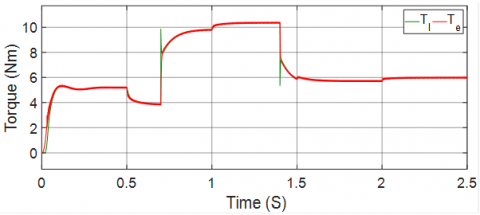
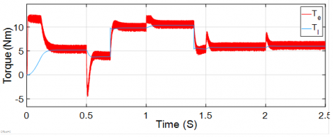
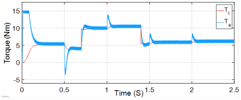
Figures 9, 10, and 11 demonstrate that the torque of the induction machine corresponds to the applied load torque using FOC, DTC, and DTC-SVM techniques, respectively, in the solar water pumping system, which is affected by variations in radiation. Initially, the pump load is subjected to a radiation intensity of 1000 W/m2. At t = 0.5 s, a decrease in torque is observed as a result of the radiation decreasing to 600 W/m2. This decrease in torque indicates that the system is mostly dependent on radiation. During the time intervals of 1 second, 1.5 seconds, and 2 seconds, the radiation levels increase to 700 W/m2, 800 W/m2, and 900 W/m2 accordingly. This increase in radiation directly impacts the torque of the induction machine, providing evidence of its susceptibility to changes in radiation.
Figure 9. Electromagnetic torque by FOC
Figure 10. Electromagnetic torque by DTC
Figure 11. Electromagnetic torque by DTC-SVM
At t = 0.7 s, a load is applied to the machine with a torque of 6 N.m. Additionally, we observe that the machine's torque aligns with the load torque temporarily. At the 1.4-second mark, we decreased the load torque by 5 N.m, resulting in a corresponding decrease in the machine's torque.
DTC-SVM exhibits reduced fluctuations in electromagnetic torque compared to conventional direct torque control, while also achieving faster dynamic reaction tracking compared to field-oriented control. The control system exhibits a highly satisfactory response during the speed reversal test, even under the rated load condition.
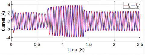
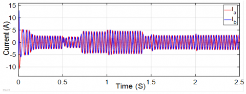
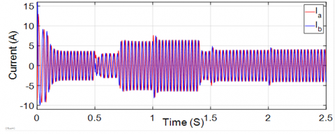
Figures 12, 13, and 14 represent the electrical currents of the machines in the binary systems of field-oriented control (FOC), direct torque control (DTC), and space vector modulation (DTC-SVM), respectively. The currents of the induction machine are influenced by both the applied load torques and the radiation change, as depicted in the pics.
Figure 12. Stator alpha-beta currents by FOC
Figure 13. Stator current by DTC
Figure 14. Stator current by DTC-SVM
The rotor and stator current components exhibit identical characteristics in all control systems. These devices exhibit sensitivity to fluctuations in torque caused by the load and have a sinusoidal form. Similar to traditional DTC, the steady state current response of the DTC space vector modulation (SVM) exhibits minimal fluctuations in stator current and a waveform that closely resembles a sinusoidal pattern, in contrast to conventional direct control methods. The stator current's ripple, which indicates the phase current and its harmonic spectrum, exerts a significant detrimental impact on the performance of the motor pump. We also observed that the dynamic response of FOC is dependent on its present amplitude, requiring more energy until the system reaches a steady state, as compared to DTC and DTC-SVM.
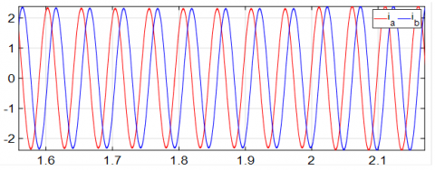
Figure 15. Stator alpha-beta currents by FOC (Zoom)
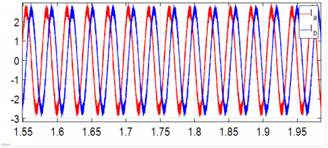
Figure 16. Stator current by DTC (Zoom)
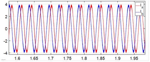
Figure 17. Stator current by DTC-SVM (Zoom)
The stator current waveforms of DTC-SVM exhibit higher qualitative characteristics compared to those of regular DTC, thanks to the use of hysteresis controllers. This distinction is particularly evident in the zoomed-in Figures 15, 16, and 17, which represent FOC, conventional DTC, and DTC-SVM, respectively.
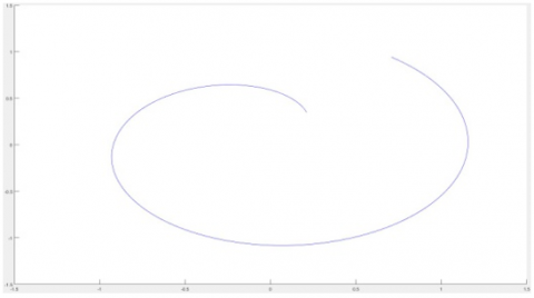
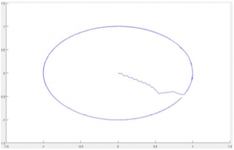
Figure 18. Start trajectory flux by FOC
Figure 19. Start trajectory flux by DTC
Figure 20. Start trajectory flux by DTC-SVM
To demonstrate the enhancements made to our studied system, we can utilize Figures 18, 19, and 20. These images display the initial paths taken by Flux for FOC, DTC, and DTC-SVM, respectively.
The reference flux value was set to 1 Wb, the greatest flux value, when FOC was applied. The same value was used for both DTC techniques. It is evident that the flux obtained by FOC surpasses the nominal flux. This has a negative impact on the motor-pump's capacity to respond quickly, which is a disadvantage compared to the flux obtained through DTC. However, the flux obtained through DTC is further enhanced by DTC-SVM.
The results suggest that employing DTC-SVM enables the flux to quickly follow a shorter path, resulting in a more efficient trajectory. In contrast, applying DTC and FOC slows down the motor-behavior pump.
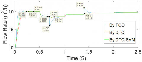
Figure 21. Flow rate of the centrifugal pump
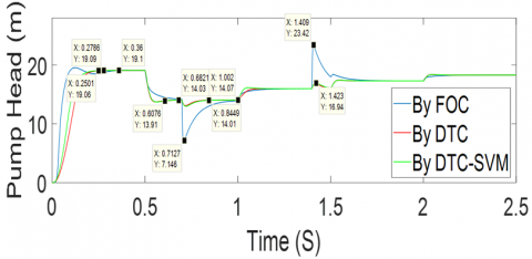
Figure 22. Head pump
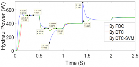
Figure 23. Power Hydraulic of the centrifugal pump
Figures 21, 22, and 23 depict the flow rate, head pump, and hydraulic power of the centrifugal pump, respectively. The figures illustrate the disparities in the dynamic performance of the pump, flow rate, pump head, and hydraulic power for the FOC, DTC, and DTC-SVM techniques. Using Direct Torque Control consistently delivers higher outputs compared to FOC, regardless of variations in load potential and radiation levels. Additionally, it may be stated that DTC-SVM exhibits a higher level of speed compared to traditional DTC. This encompasses any visible phenomena, which may be easily observed via the initial performance of the motor-pump system until it reaches a stable state, in comparison to conventional DTC and FOC. It is important to note that ordinary DTC is less effective than DTC-SVM in monitoring the performance of a dynamic at low speeds. With a pump speed of 1,000 revolutions per minute, it can be stated that the pumping system's tracking performance is excellent.
At an irradiance of 1000 w/m2, the reference speed mode was initially configured to 100 rad/s. The diagram illustrates the time delay in the engine speed reaching the desired reference speed using FOC, beyond the nominal speed. This discrepancy is considered a significant and undesirable mistake. However, DTC and DTC-SVM provide a quicker reaction without surpassing the specified speed. The reason for this is that DTC has a quicker dynamic reaction and exceptionally high performance. The yield of the induction machine is crucial for the operation of the centrifugal pump. Additionally, the diagram illustrates the flaws that arise while employing FOC. while we manipulate the load by increasing or decreasing it, as demonstrated at 0.7 s and 1.4 s, respectively, we observe a noticeable delay in response and sluggish mechanical performance. This can be attributed to the sensitivity of the system while altering parameters. However, DTC and DTC-SVM exhibit a more rapid response and commendable mechanical performance. The sensitivity of the parameters is significantly high when employing FOC, notably low when utilizing DTC, and predominantly low when employing DTC-SVM. This great dynamic performance is also evident during fluctuations in radiation. Furthermore, the extent of mistakes caused by parameter detuning is lower in comparison to FOC. Additionally, it possesses frequency switching capabilities that enable it to alter speed more rapidly than FOC. Furthermore, these factors have a direct impact on the efficiency of the load, specifically the centrifugal pump that we are studying in our research.
The presented paper conducted a simulated study of a water pumping system utilizing the Simulink-MATLAB program. We utilized fuzzy logic control (FLC) to enhance the output voltage of the photovoltaic (PV) system. Additionally, we employed various techniques, including field-oriented control (FOC), direct torque control (DTC), and space vector modulation (DTC-SVM), to regulate the induction machine that powers the centrifugal pump. We then conducted a comparative analysis of these methods. Based on the results, we can infer that the performance of the motor-pump is improved by using direct torque control, resulting in a faster dynamic response. Additionally, we combine it with space vector modulation to reduce the harmonics generated by the direct torque control. This is seen in the accelerated dynamic response of the induction motor, enhanced efficiency, and superior performance with an improved flow rate regardless of variations in load or radiation. Furthermore, it is possible to suggest this as a potential future project, given that these outcomes weren't achieved through an experimental configuration of the entire system using developer techniques. While we have achieved excellent results in optimizing energy usage from photovoltaic (PV) systems, we can further improve our PV system by incorporating further artificial intelligence techniques.
[1] Jafari, M., Malekjamshidi, Z. (2020). Optimal energy management of a residential-based hybrid renewable energy system using rule-based real-time control and 2D dynamic programming optimization method. Renewable Energy, 146: 254-266. https://doi.org/10.1016/j.renene.2019.06.123
[2] Nkembi, A.A., Santoro, D., Cova, P., Delmonte, N. (2023). A novel energy management control scheme for a standalone PV system in a DC nanogrid. Electronics, 12(4): 4725. https://doi.org/10.3390/electronics12234725
[3] Parveen, H., Sharma, U., Singh, B. (2020). Pole reduction concept for control of SyRM based solar PV water pumping system for improved performance. IEEE Transactions on Industrial Electronics, 68(7): 5650-5660. https://doi.org/10.1109/TIE.2020.3000089
[4] Massaq, Z., Abounada, A., Brahmi, A., Ramzi, M. (2020). Control of PV-battery based hybrid water pumping system under sudden irradiance and speed changes. In 2020 IEEE 6th International Conference on Optimization and Applications (ICOA), Beni Mellal, Morocco, pp. 19631649. https://doi.org/10.1109/ICOA49421.2020.9094525
[5] Lin, S., Ma, T., Javed, M.S. (2020). Prefeasibility study of a distributed photovoltaic system with pumped hydro storage for residential buildings. Energy Conversion and Management, 222: 113199. https://doi.org/10.1016/j.enconman.2020.113199
[6] Bowden, M. (2021). A survey on photovoltaics technology for water pumping. Journal of Machine and Computing, 1(2): 86-96. https://doi.org/10.53759/7669/jmc202101010
[7] Yussif, N., Sabry, O.H., Abdel-Khalik, A.S., Ahmed, S., Mohamed, A.M. (2020). Enhanced quadratic V/f-based induction motor control of solar water pumping system. Energies, 14(1): 104. https://doi.org/10.3390/en14010104
[8] Mirza, A.F., Mansoor, M., Ling, Q., Yin, B., Javed, M.Y. (2020). A salp-swarm optimization based MPPT technique for harvesting maximum energy from PV systems under partial shading conditions. Energy Conversion and Management, 209: 112625. https://doi.org/10.1016/j.enconman.2020.112625
[9] Беларусси, У., Калинин, В.Ф., Амел, Т. (2021). Эффективное нечеткое логическое управление для оптимизации фотоэлектрической системы. Вестник Тамбовского Государственного Технического Университета, 27(1): 62-72. https://doi.org/10.17277/vestnik.2021.01.pp.062-072
[10] Massaq, Z., Abounada, A., Ramzi, M. (2021). Fuzzy and predictive control of a photovoltaic pumping system based on three-level boost converter. Bulletin of Electrical Engineering and Informatics, 10(3): 1183-1192. https://doi.org/10.11591/eei.v10i3.2605
[11] Poompavai, T., Kowsalya, M. (2020). Investigation of standalone solar photovoltaic water pumping system with reduced switch multilevel inverter. Frontiers in Energy Research, 8: 9. https://doi.org/10.3389/fenrg.2020.00009
[12] Abouzeid, A.F., Guerrero, J.M., Endemaño, A., Muniategui, I., Ortega D., Larrazabal, I., Briz, F. (2020). Control strategies for induction motors in railway traction applications. Energies, 13(3): 700. https://doi.org/10.3390/en13030700
[13] Reddy, M.R.P., Deepak, K., Jaya Sree, K., Lakshmi, M.B. (2021). Reduction of steady state ripple of vector controlled induction motor drives by combining the techniques of FOC and DTC. Annals of the Romanian Society for Cell Biology, 25(1): 5910-5920.
[14] Pham, N.T., Le, T.D. (2020). A novel FOC vector control structure using RBF tuning PI and SM for SPIM drives. International Journal of Intelligent Engineering and Systems, 13(5): 429-440. https://doi.org/10.22266/ijies2020.1031.38
[15] Prasad, R.M., Mulla, M.A. (2020). Mathematical modeling and position-sensorless algorithm for stator-side field-oriented control of rotor-tied DFIG in rotor flux reference frame. IEEE Transactions on Energy Conversion, 35(2): 631-639. https://doi.org/10.1109/TEC.2019.2956255
[16] Marulasiddappa, H.B., Pushparajesh, V. (2021). Review on different control techniques for induction motor drive in electric vehicle. In IOP Conference Series: Materials Science and Engineering, Erode, India, p. 012142. https://doi.org/ 10.1088/1757-899X/1055/1/012142
[17] Sakthi, V., Sivasubramanian, A. (2020). Torque and flux ripples minimization in DTC based IM drive using ANFIS controller. Journal of Critical Reviews, 7(19): 3720-3729. https://doi.org/10.31838/jcr.07.19.443
[18] Fadhil, G.M., Abed, I.A., Jasim, R.S. (2021). Controlling of induction motor using grey wolf optimization algorithm. In Journal of Physics: Conference Series, Basrah, Iraq, p. 012007. https://doi.org/10.1088/1742-6596/1773/1/012007
[19] Sahu, A., Mohanty, K.B., Mishra, R.N. (2020). Improved sector-based DTC-SVM for induction motor drive using hybrid fuzzy-PI controller. In Advances in Electrical Control and Signal Systems: Select Proceedings of AECSS 2019, Singapore, pp. 415-428. https://doi.org/10.1007/978-981-15-5262-5_30
[20] Boukahil, F.Z., Menadi, A., Abdeddaim, S., Betka, A. (2022). Experimental validation of extremum seeking and sliding mode-based control for an autonomous PV system under partial shading conditions. Journal of Electrical Systems, 18(4): 520-532.
[21] Kumar, M.V., Salma, U. (2020). Modeling and simulation of a three phase grid connected photovoltaic system. European Journal of Molecular & Clinical Medicine, 7(5): 244-261.
[22] Markov, B.G., Markova, D.G. (2020). Comparison of methods for control of linear induction motors. In 2020 55th International Scientific Conference on Information, Communication and Energy Systems and Technologies (ICEST): Niš, Serbia, pp. 141-144. https://doi.org/10.1109/ICEST49890.2020.9232715
[23] Loubna, A., Riad, T., Salima, M. (2020). Standalone photovoltaic array fed induction motor driven water pumping system. International Journal of Electrical and Computer Engineering (IJECE), 10(5): 4534-4542. https://doi.org/10.11591/ijece.v10i5.pp4534-4542
[24] Boukahil, F.Z., Charrouf, O., Abdeddaim, S., Betka, A., Menadi, A. (2022). The shading effect on photovoltaic (GPV) based on reverse osmosis (RO) desalination system in Algeria. European Journal of Electrical Engineering, 24(4): 185-193. https://doi.org/10.18280/ejee.240403
[25] Sharma, U., Singh, B. (2020). Utility-tied solar water pumping system for domestic and agricultural applications. Journal of the Institution of Engineers (India): Series B, 101: 79-91. https://doi.org/10.1007/s40031-020-00426-z
[26] Veeramanikandan, P., Selvaperumal, S. (2021). Investigation of different MPPT techniques based on fuzzy logic controller for multilevel DC link inverter to solve the partial shading. Soft Computing, 25(4): 3143-3154. https://doi.org/10.1007/s00500-020-05370-0
[27] Ali, M.N., Mahmoud, K., Lehtonen, M., Darwish, M.M.F. (2021). An efficient fuzzy-logic based variable-step incremental conductance MPPT method for grid-connected PV systems. IEEE Access, 9: 26420-26430. https://doi.org/10.1109/ACCESS.2021.3058052
[28] Sreelakshmi, S., Sujatha, M.S. (2020). Mitigation ofics for eleven-level cascaded multilevel inverter using SPWM and SHE techniques. Helix, 10(2): 168-177.
[29] Upadhyay, D., Khan, S.A., Ali, M., Tariq, M., Sarwar, A., Chakrabortty, R.K., Ryan, M.J. (2021). Experimental validation of metaheuristic and conventional modulation, and hysteresis control of the dual boost nine-level inverter. Electronics, 10(2): 207. https://doi.org/10.3390/electronics10020207
[30] Preetha Roselyn, J., Sen, D., Lal, P., Purkayastha, N., Nithya, C. (2020). Development of hysteresis current controller for power quality enhancement in grid connected PV system. International Journal of Electrical Engineering and Technology, 11(4): 8-21.
[31] Mahfoud, S., Derouich, A., El Ouanjli, N., Mohammed, T., Hanafi, A. (2021). Field oriented control of doubly fed induction motor using speed sliding mode controller. In E3S Web of Conferences, Agadir, Morocco, p. 01061. https://doi.org/10.1051/e3sconf/202122901061
[32] Ben Salem, F., Feki, M. (2019). An improved DTC Induction motor for electric vehicle propulsion: An intention to provide a comfortable ride. Solving Transport Problems: Towards Green Logistics, 185-201. https://doi.org/10.1002/9781119686750.ch8
[33] Alhamin, S., Yi, S.S., Kai, C.S., aira Zambri, N., Mustafa, F., Lim, A. (2020). Artificial intelligence based direct torque control of induction motor drive system. Progress in Engineering Application and Technology, 1(1): 173-190.
[34] Singh, P., Gaur, P., Mittal, A.P. (2020). Battery connected photovoltaic water pumping system with DTC drive. In 2020 International Conference on Power Electronics & IoT Applications in Renewable Energy and its Control (PARC), Mathura, India, pp. 437-442. https://doi.org/10.1109/PARC49193.2020.236648
[35] Belaroussi, O., Terki, A., Ammar, A., Fedorovich, K.V. (2022). Developing and implementing the performance of induction motors used in well pumping systems. European Journal of Electrical Engineering, 24(5-6): 247-256. https://doi.org/10.18280/ejee.245-603
[36] Potturi, S., Mandi, R.P. (2020). Latest advances in DTC control of induction motors. International Journal of Recent Technology and Engineering (IJRTE): 8(6S): 120-123. https://doi.org/10.35940/ijrte.F1008.0386S20