Ahmed Yahya Qasim![]() | Fadhil R. Tahir
| Fadhil R. Tahir![]() | Ahmed Nasser B. Alsammak*
| Ahmed Nasser B. Alsammak*![]()
© 2023 IIETA. This article is published by IIETA and is licensed under the CC BY 4.0 license (http://creativecommons.org/licenses/by/4.0/).
OPEN ACCESS
Power quality (PQ) has taken center stage in contemporary discussions owing to the escalating usage of power electronic gadgets. This paper throws light on the unified power quality conditioner (UPQC), an instrumental tool for load current balancing, voltage regulation, harmonics mitigation, sag and swell mitigation, and load-reactive power demand compensation within a three-phase, three-wire distribution structure catering to a variety of combinations of non-linear and unbalance loads. In scenarios devoid of UPQC, phenomena such as voltage sag, swell, and supply voltage distortion pose a potential threat to the sensitive equipment connected to the system. UPQC ingeniously amalgamates a series active power filter (APF) with a shunt APF, thereby addressing a majority of PQ issues. The control over the shunt APF is achieved via synchronous reference frame (SRF) theory, while the series APF is governed by the power angle control (PAC) technique. The application of SRF-PAC techniques manifests a high degree of robustness, effectively counterbalancing the VA loading imbalance in both series and shunt APFs within the UPQC system. This equilibrium is attained through the fair distribution of reactive load power between the two APFs. The simulation outcomes convincingly illustrate that UPQC minimizes the impact of supply voltage variations and harmonic currents on the power line under diverse loads, with the total harmonic distortion (THD) of load voltages and source currents generated being confined to less than 5%.
voltage swell and sag, reactive power compensation, harmonic elimination, UPQC, power angle control (PAC)
The distribution system is becoming more complicated due to a fast expansion in capacity and the addition of modern loads. This generates new power quality challenges inside the distribution system. Keeping up with PQ criteria is getting more difficult, posing a challenge for several researchers [1]. "Electric PQ means keeping the almost sinusoidal waveform of voltages and currents on the distribution bus at the rated magnitude and frequency". As the power system develops, the number of nonlinear loads like transformers, electric furnaces, and power electronic equipment are growing quickly [2]. System PQ distortion is caused by nonlinear loads linked to the point of common coupling (PCC), where this is harmful to the power grid, more costly electrical equipment will be damaged by voltage distortion, and system losses will rise [3]. The UPQC is one of the suitable solutions for mitigating the PQ issues on the source and load sides [4]. The UPQC consists of a shunt and a series APFs connected by a common DC-link. This device can mitigate the PQ issues, including voltage imbalance, voltage harmonics, voltage sag/swell, flickers in voltage, current harmonics, reactive current, current unbalance, etc. [5].
The voltage compensating on a system can be controlled using one of four control approaches: UPQC-P, UPQC-Q, UPQC-VAmin, and UPQC-S [6]. The UPQC-Q among these methods can only compensate for voltage sag while it cannot compensate for voltage swell. The series APF injects voltage in quadrature with the source current. So, a series inverter doesn't require any active power to compensate for the voltage drop [7]. The UPQC-P employs active power to provide voltage sag compensation, which, unlike the other three methods, needs a minimum amount of series injection voltage. In UPQC-VAmin, to achieve optimum series APF volt-ampere (VA) loading, the series APF injects a voltage at the optimal angle at the voltage sag/swell situation [8]. Finally, the UPQC series inverter is controlled to execute concurrent voltage sag/swell compensation and load reactive power sharing with the shunt inverter using the maximum VA capability of series and shunt APFs. In this case, the UPQC series inverter gives both active and reactive power, so it is named UPQC-S [9].
The first practical UPQC was created by Fujita and Akagi [10], who used a shunt APF and a series APF connected through a DC connection. Since then, this device has been the focus of much study, resulting in several topologies, models, and control schemes of this device. In Jindal et al. [11] suggested a novel connection for a unified power quality conditioner (UPQC) to enhance the PQ of two feeds in a distribution system. Because the UPQC is linked among two various feeds, this link is known as an interline UPQC (IUPQC). Feeder-1 provides an unbalanced and nonlinear load (L-1), whereas Feeder-2 provides a sensitive load (L-2). This IUPQC was designed to protect the sensitive load from upstream disturbances and regulate the voltage at the Feeder-1 terminals. The IUPQC has been tested under several scenarios, including a fault on one feeder, voltage drops on both feeders, and a change in the load. The IUPQC could manage systems with imbalanced and distorted loads.
In a study conducted by Khadkikar [8], the author examined the challenges of controlling, operating, and rating UPQCs in voltage sag and swell scenarios. The Power Angle Controller (PAC) of the UPQC concept was employed as a controller to ensure an effective power angle between the resultant load voltage and the source voltage. There are two proposed control strategies: fixed and variable PAC techniques. It has been shown that these strategies may impact the total kVA loadings of shunt and series APFs. Series and Shunt APFs share different amounts of active and reactive power dependent on the mechanisms utilized (fixed or variable) without changing the system's overall power balance. For voltage swell compensations, the constant power angle technique may be preferable, while for voltage sag compensations, the variable power angle method may be superior.
Integration of UPQC with the microgrid and the utility to mitigate PQ-related difficulties was developed by Samal and Hota [12]. This system includes photovoltaics, a fuel cell, wind turbines, batteries, and various loads (coupled to the bus). According to the results, the distribution PQ issues can be solved by UPQCs connected to both the utility and the microgrid. Also, the microgrid could switch to stand-alone mode while reliably powering critical loads in the event of a significant failure or power disruption in the main grid.
In a study performed in 2018, Lakshmi and Ganguly [13] devised a multi-topical planning approach aimed at the best location of an open UPQC-O. This strategy aimed to enhance the hosting capacity of PV systems and minimize energy loss in distribution networks. The series and shunt converters of the UPQC-O model are not connected to a common DC link. To find out where the UPQC-O inverters should be placed and the optimal PV generating capacity in each bus, the Pareto-dominance-based technique was employed to optimize the objective functions simultaneously. The operational constraints in this planning problem are the maximum PV generating capacity in each bus, the maximum line current flow, and the percentage of voltage-sag-mitigated demand. As a method for achieving a solution, the multi-objective particle swarm optimization approach was used. According to the findings, installing PV in distribution systems minimizes energy loss.
In 2018, Campanhol et al. [14] presented comprehensive research on the stability analysis, size, and power flow of a multifunctional 3-phase DG system comprised of a one-stage Photovoltaic linked to the UPQC. Whenever the Distributed generation system is placed between the grid and general loads or an AC microgrid, the UPQC acts as a bidirectional interface. This study stands out as a key method for effectively developing inverters, considering the nonlinear characteristics of the load and, the PV array's maximum power production and the effect of various current disturbances in the grid voltages. Additionally, two methods for reducing the UPQC inverters' power rating were shown and addressed. The analysis of system stability showed that the system stability was ensured by the voltage and current controllers that have been employed. Experiment findings were provided, taking into account various static circumstances of operation for the PV-UPQC system in addition to simulation results, which demonstrated the efficacy of overcoming the parallel converter's over-power rating.
Mansor et al. [15] investigated the effectiveness of the UPQC in mitigating PQ problems and harmonics caused by non-linear loads connecting to the grid. Battery Energy Storage System (BESS) and Photovoltaic System (PV) backed up the UPQC, where the PV system supplies the load with real power. Since the PV-BESS system provided a constant supply, the DC voltage was stable. As a result, the algorithm used to regulate the DC link voltage may be simplified. The shunt and series APF compensator successfully implemented the STF-UVG technique for synchronization phases to create reference voltage and current. The suggested method has shown that the source current harmonics match IEEE-519.
A hybrid UPQC model that includes distribution generation (HCUPQC-DG) was proposed by Wang et al. [16] in 2021. The HCUPQC-DG has a pair of DC ports located at its DC link. The low-voltage DC port is directly connected to the DG, while the front-end DC-DC converter establishes a connection between the high-voltage DC port and the DG. Most active power may flow directly from the DG to the AC load or grid through the direct power flow path. Thus, the power capacity of the front-end dc-dc converter was reduced significantly, with the conversion was greatly improved. In the HCUPQC-DG architecture that has been proposed, the voltage of the DG wasn't constrained by the voltage of the UPQC's common DC bus, so it could be low and vary greatly. Since some of the DG's active power was transmitted via the direct power flow channel, the front-end DC-DC converter's power capacity was reduced.
In 2021, Abdalaal and Ho [17] developed a new control approach for transformerless UPQC (TL-UPQC) so that distribution networks could take in and send out reactive power from and to the grid. One converter regulated both the voltage on the load side and the voltage on the input grid. With no additional sensor circuits, the improved control strategy operated based on local data gathered by the TL-UPQC. With the help of the suggested enhanced control strategy, the TL-UPQC can improve the voltage profile of the input grid and eliminate the components of harmonic caused by nonlinear load. It was also able to compensate for voltage fluctuations across sensitive loads quickly. The practical results confirmed the system's ability to regulate the voltage at the PCC and simultaneously powering linear and nonlinear sensitive loads.
Krishna et al. [18] introduced a UPQC controller based on Fractional Order Fuzzy Logic (FOFL) to deal with PQ issues in (2022). Four different controllers, the FLC, Adaptive FLC, the Fractional Order Proportional Integral (FOPI), and the Fractional Order FLC, were used to explain the operation of the UPQC. Compared to UPQCs using FOPI controllers, UPQCs using FOFL controllers are significantly effective at addressing power quality issues.
A passive sliding mode control (PSMC) method was created by Jiang and Zhang [19] for a modular multilevel converter (MMC-UPQC) system experiencing grid imbalance. Unbalanced power grids were represented using a mathematical model structurally comparable to MMC-UPQC. A positive and negative sequence separation technique was used to split the detected quantity without PLL. The suggested controller could enhance the control of system parameters, response speed, and compensation performance.
This work is based on a steady-state analysis of UPQC under different operating conditions. Section 2 of this study describes the UPQC configuration. Section 3 of the UPQC's Proposed Control explains this. While section 4 highlights the MATLAB/Simulink simulation outcomes, and Section 5 concludes the study.
The UPQC configuration that was employed in the study is depicted in Figure 1 [20]. This configuration is based on the most common UPQC architecture, the 3-phase, 3-wire configuration.
Figure 1. The UPQC diagram [20]
Shunt and series APFs are combined into the UPQC configuration and connected back-to-back via a common DC bus. Shunt APF, also referred to as DSTATCOM, is employed to mitigate the PQ problems related by current through balance supply currents, compensate harmonic currents to eliminate harmonics in the current of load, control DC-link voltage, and compensate reactive power to enhance the power factor.
The conventional series APF (also called a DVR) maintains load voltage stability and enhances the PQ related by voltage via injecting voltage to smooth out fluctuations in the source voltage, injecting harmonic voltages to insulate the load bus from source voltage harmonics, and injecting the necessary active power components to maintain the load voltage at the desired level. The voltage provided by the series APF is injected into each phase using single-phase series injection transformers. At the shunt, APF's output, an interface inductor is utilized. At the end of a series of APF, an LC filter removes high-frequency voltage components generated by the PWM switching of these APFs [6].
Combining shunt and series inverters, this section presents the proposed UPQC control technique. To compensate for voltage-based PQ problems, the UPQC's Series APF acts as a voltage source, injecting the necessary voltage into the supply voltage. In contrast, shunt APF acts as a current source, injecting the suitable current into the system to compensate for load-side power quality problems. The DC-link voltage of UPQC is also controlled by a shunt APF [21]. P-q theory and SRF theory are two of the most often utilized techniques for reference signal generation that are based on the time domain. Methods based on p-q or SRF theory are simpler when compared to more sophisticated control approaches used of adaptive filters like the adaptive notch filter, etc. [22]. PAC is a method that successfully distributes reactive power between the shunt and series APF without hindering with UPQC's primary function, relieving some of the load on the shunt converters [23]. The following is an in-depth description of the control of each of the APFs. The power angle control (PAC) technique was used to control the series APF, and synchronous reference frame (SRF) theory was used to control the shunt APF.
3.1 Control of the series APF
In the PAC approach, the series APF injects the required series voltage to compensate for problems with the source voltage's power quality while supplying a portion of the reactive power to the load. The phase difference between the load voltage and the supply voltage results from injecting series voltage at a certain angle with the source current to supply a portion of the reactive power to the load. To generate reference signals, the power angle (δ) with respect to the source voltage/current must be determined [24]. Using the suggested PAC approach, control of a series APF can be broken down into two parts: power angle estimate and creating pulses for switching.
3.1.1 Power angle estimate
Figure 2 illustrates the phasor diagram for UPQC using the PAC technique. In this diagram, VS represents the nominal supply voltage with its RMS value equal to (k). In normal conditions, the load voltage (VL) and source voltage (Vs) form an angle (δ). A series APF injects a series voltage (VSr), the phasor difference between the source and load voltages [21]. The operations of UPQC-P and UPQC-Q are shown at angles of δ=0 and φsr=90°, respectively, whereas UPQC-S is operated at any angle 0<δ<90° [25].
In the fixed PAC method, when sag occurs, the supply voltage's magnitude RMS is lowered to k′. The magnitude of the series voltage (V ′Sr) injected during sag will be lower than that of the VSr injected under health operation. The condition is reversed when there is a system swell. The series voltage (V ′′Sr), as seen in Figure 2, is the greatest in all three circumstances under swell. As a result, the rating of the series APF should be chosen based on the maximum swell situation if the fixed power angle approach is utilized. The series APF rating will be underused in normal operation due to the low incidence of swells, which is a disadvantage of this method [26].
Figure 2. Phasor diagram of UPQC based on the PAC method
In the variable PAC method, when sag or swell happens, the value of δ is changed. If there is sufficient demand of reactive power from load, series APF works at its total rating during normal operation. When sag or swell occurs, these power angles are changed to maintain the series inverter's maximum capacity [26].
Under sag conditions, the following equations can be obtained from Figure 2 [24].
$x=k \cos \delta$ (1)
$y=k \sin \delta$ (2)
$\left|V_{s r}{ }^{\prime}\right|=\sqrt{y^2+\left(k^{\prime}-x\right)^2}$ (3)
$\left|V_{s r}^{\prime}\right|=\sqrt{k^2+k^{\prime 2}-2 k k^{\prime} \cos \delta}$ (4)
where, (fS) is assumed to be the fraction of voltage sag and (fSr) to be the ratio of the series voltage (V ′Sr) to the rated source voltage k, further simplifications result in the following formulations [24]:
$f_S=k^{\prime} / k$ (5)
$f_{S r}=\left|V_{s r}^{\prime}\right| / k$ (6)
$f_{S r}=\sqrt{1+f_S^2-2 f_S \cos \delta}$ (7)
$\delta=\cos ^{-1}\left[\frac{1+f_S^2-f_{s r}^2}{2 f_s}\right]$ (8)
If series APF provides a rated voltage (VSr,max), then $\delta$ will be at its maximum value at a particular supply voltage. The following can be concluded from Eq. (8) [21]:
$\delta_{\text {max }}=\cos ^{-1}\left[\frac{1+f_S^2-f_{s r-\max }^2}{2 f_S}\right]$ (9)
It is important to note that $\delta_{\max }$ varies with the source voltage and is not a constant because fS is present in Eq. (9). Eq. (10) is used to calculate the actual value of $\delta_A$ in the case of normal UPQC from the reactive power (QSr) supplied by series APF and the load active power (PL) [27].
$\delta_A=\sin ^{-1}\left(\frac{Q_{s r}}{P_L}\right)$ (10)
where, the following equation can be used to calculate the maximum reactive power handled by a series APF under normal supply voltage situations [26].
$Q_{s r-\max }=P_{L} \sin \delta_{\max }$ (11)
3.1.2 Creating pulses for switching
The next step for series APF after the power angle has been determined is to generate reference load voltages leading to supply voltages by power angle. Figure 3 depicts the control block diagram of the series converter controller. The unit vector template generation (UVTG) approach is used to generate the reference signals for the series inverter. A phased locked loop (PLL) has been used to produce (ωt), which corresponds to phase A's fundamental component [28]. When the produced (ωt) is combined with the estimated $\delta$ computed by the power angle estimator block, Eq. (12) is used to generate three-phase balanced unit vectors [24].
$\left[\begin{array}{l}V s a \\ V s b \\ V s c\end{array}\right]=\left[\begin{array}{c}\sin (\omega t+\delta) \\ \sin (\omega t+\delta-2 \pi / 3) \\ \sin (\omega t+\delta+2 \pi / 3)\end{array}\right]$ (12)
Figure 3. Series converter controller employing PAC technique
The unit vectors are then multiplied by the desired magnitude of the load voltages (VLm) to produce reference load voltages (V *Labc). Series inverter PWM controllers compare actual load (VLabc) and reference load (V*Labc) voltages to create switching signals for the IGBT switches.
3.2 Shunt APF control
This research presents a shunt active power filter (APF) that can be utilized to compensate for the current harmonics and reactive power of a nonlinear load. The shunt APF was controlled by the SRF method, as shown in Figure 4 [20]. The proposed SRF-based shunt APF reference supply current signal is generated from source voltages, load currents, and DC link voltages. The abc-dq0 transformation (Park's transformation) was used to get the basic component of load current, as well as the ($\omega t$) signal required for this conversion has been generated by supplying the source voltages to PLL [29].
A low pass filter has been used to get the load current average component ($I_{L d}^{-}$) from the d-axis component. A PI controller calculates the current required (Id loss) for maintaining the dc-link voltage constant by comparing the dc-link voltage (Vdc) to its reference value (V *dc). As shown in Eq. (13), the source's current fundamental reference component $I_{s d}^*$ is found by adding the ($I_{L d}^{-}$) and the loss current (Id loss) [30].
$I_{s d}^*=I_{L d}^{-}+I_{d \ l o s s}$ (13)
To compensate for imbalance, harmonics, and reactive power in the source current, the zero-and negative-sequence components of the reference source current ($I_{s 0}^*$ and $I_{s q}^*$) in the zero- and q-axes are set to zero. Inverse Park's transform has been used to generate the current reference signals $I_{s a b c}^*$, where the 3-phase balanced reference source currents ($I_{s a b c}^*$) are obtained from ($I_{s d}^*$) in Eq. (14) [20].
$\left[\begin{array}{c}I_{s a}^* \\ I_{s b}^* \\ I_{s c}^*\end{array}\right]= T^{-1}\left[\begin{array}{c}I_{s d}^* \\ 0 \\ 0\end{array}\right]$ (14)
In order to create the inverter's IGBT switching signals, a hysteresis band current controller compares the generated reference source currents ($I_{s a b c}^*$) with the actual source currents ($I_{s a b c}$), that compensates for all problems with current, such as reactive power, current harmonics, zero-and negative sequence components, dc-link voltage regulator, and load-current imbalance.
Figure 4. Shunt converter controller using SRF method
The specification of harmonic voltage and current restrictions for supply voltage may be found in IEEE Standard 519-1992 [31].
This section presents the results of a simulation conducted on a three-phase, three-wire UPQC that utilizes PAC-SRF techniques. The simulation aimed to evaluate the effectiveness of the UPQC in mitigating voltage sag and swell, compensating for reactive power generated by loads, and removing current and voltage harmonics across different load scenarios. MATLAB/SIMULINK has been used to implement the proposed control method. The equations in the study [32] were used to determine values for the system parameters. The UPQC system parameters are shown in Table 1. UPQC has been used the PAC-SRF control techniques in the following three cases:
Table 1. UPQC parameters
|
Supply |
400V, 50Hz |
|
DC Link |
Vdc=700V, Cdc=5000µF |
|
Series APF |
Lse=7mH, Cse=100µF |
|
Shunt APF |
Lsh=2mH, Csh=100µF |
|
The Load in Case 1 Nonlinear Load |
Diode bridge rectifier in 3-ph followed by RL load RL=25Ω, LL=10mH |
|
The Load in Case 2 Unbalance-Linear Load |
10Ω/50mH, 10Ω/10mH, 20Ω/20mH |
|
The Load in Case 3 |
Load 1=10kW+j8Kvar Load 2=5kW+j5Kvar |
Case 1: UPQC effectiveness with nonlinear loads
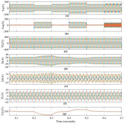
The UPQC has been tested in this part under voltage sag, swell, and distortion with nonlinear load conditions. The nonlinear Load is a 3-phase diode rectifier load that supplies a DC-load. As shown in Figure 5 (a), the UPQC has been operated with a 30% voltage sag at (time=0.2-0.3 sec) and a 30% voltage swell at (time=0.4-0.5 sec). Also, harmonic supply voltage has been generated at (time=0.6-0.7 sec) by connecting a 5th harmonic (10% of the fundamental supply voltage) and a 7th harmonic (15% of the fundamental supply voltage) in series with the source voltage. Figure 5 (b-e) depicts the compensation voltage, load voltage, source current, shunt current, load current, and DC-link voltage, respectively.
Figure 5. Case 1, simulated results with nonlinear loads a) Supply voltage, b) Compensator voltage, c) Voltage at the load, d) Supply current, e) Compensator current, f) Load current, g) DC-link voltage
The series inverter injected a difference voltage into the system during sag at (time=0.2-0.3 sec) to keep the voltage magnitude at the load terminals constant, while the series inverter absorbs excess voltage in voltage swell situations at (time=0.4-0.5 sec). To compensate for voltage harmonics, the sum of the 5th and 7th harmonics was injected into the series APF at (time=0.6-0.7 sec), as illustrated in Figure 5 (b). The load voltage is kept constant, and the distortion-free voltage is achieved by utilizing a series APF, as shown in Figure 5 (c).
At sag condition, the shunt APF draws the actual power from the grid and transfers it through the DC-link capacitor to the series APF, where the shunt APF must draw extra source current. The power balance is maintained by raising the source current when the voltage sags. In contrast, the source current is decreased in a swell situation to recover the surplus power generated by the swell voltage in the supply, as shown in Figure 5 (d).
The load current that results from connecting a nonlinear load to a sinusoidal voltage is not sinusoidal. Many issues, including voltage fluctuations, may be produced by harmonics in non-sinusoidal current. The current harmonics generated by nonlinear loads have been compensated by the shunt active power filter. Compensatory and load currents are shown in Figure 5 (e-f). The source's voltage sag produces small decreases in the DC voltage, and its voltage swell causes slight increases in the DC voltage, where the DC voltage keeps constant at 700 Vdc, as seen in Figure 5 (g).
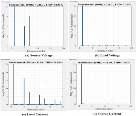
As seen in Figure 6, the THD of the source voltage at distortion voltage condition was 18.09%, and the load current was 20.06%. After compensation, the THD of the load voltage is 2.12%, and the source current is 1.42%, while the THD of the load voltage at sag and swell voltage is less than 2.42%, and the source current is 1.67%. The THDs of load voltage and source current are maintained at less than 5%, which is required according to IEEE Standard 519.
Figure 6. The THD for (a) Supply voltage at distortion, (b) Load voltage at distortion, (c) Load current (d) Supply current at voltage swell and sag
Case 2: UPQC effectiveness with unbalanced loads
The UPQC performance has been examined in tests with changing source voltage under the same conditions in case (1) (sag, swell, and distortion source voltage) with unbalanced loads. To simulate an unbalanced load, a three-phase load with various of impedances has been connected to the grid. The amplitudes of the currents drawn by the load are unequal where the unbalanced loads were used.
The source voltage, compensation voltage, load voltage, source current, shunt current, load current, and DC-link voltage are shown in Figure 7 (a-e), respectively. Figure 7 (c) illustrates that the magnitude of the load voltage has been kept constant and devoid of harmonics during sag, swell, and distortion voltage situations by using a series APF.
As illustrated in Figure 7 (d), the shunt APF compensates the zero/negative current sequences to provide a balanced source current, and a steady dc-voltage is maintained by the shunt APF as shown in Figure 7 (g). Under sag, swell, and distortion voltage situations, the THD of the load voltage is less than 2.28%, and the THD of the supply current is less than 2.71%.
Figure 7. Case 2, simulated results with unbalanced loads a) Supply voltage, b) Compensator voltage, c) Voltage at the load, d) Supply current, e) Compensator current, f) Load current, g) DC-link voltage
Case 3: UPQC performance under load changing conditions
Using the suggested PAC approach, the total reactive power of the load is the sum of the reactive power shared by the series and shunt APFs of the UPQC. The power angle δ changes depending on the load active power (PL) and load reactive power (QL) values change; as a result, the reactive powers of both the series and shunt filters are changed.
The UPQC performance under changing load conditions has been examined, where the UPQC is tested with changing PLand QL. The load demand is constant at (S=10kW+j8 kVRA) value from t=0 sec to t=0.2 sec, then at t=0.2 sec, it suddenly increases to (S=15kW+j13 kVRA). The source current was raised to compensate for the load active power demand, and the source current and the load voltage have remained balanced and sinusoidal, as shown in Figure 8 (c-d). The DC link voltage stayed constant, as illustrated in Figure 8 (g).
Figure 9 displays the results of the UPQC test with changed powers as an outcome of power angle control. The nominal load reactive power rating is taken to be QL=13kVAR. Figure 9 (e) demonstrates that the demand for load-reactive power is within the shunt APF VAR compensation limit (8 kVAR) at (time=0-0.2 sec); therefore, the shunt APF has responded swiftly to compensate the reactive power of load alone. The power angle in this status equals zero, as depicted in Figure 9 (f). Also, there is no reactive power provided by the supply, as shown in Figure 9 (c).
When the load is changed to 15kW+j13kVRA, in light of the fact that the load-reactive power demand exceeds the shunt APF compensation limit, the series APF should share a part of the load-reactive power demand. In this situation, the shunt APF delivers its maximum reactive power (=9 kVAR), and the remaining reactive power that is equal to (4 kVAR) is provided by the series APF with the suitable power angle control that is equal to (14.8°), as shown in Figure 9 (d-f). As an outcome, the total cost of UPQC is decreased as the shunt APF rating is lowered while the series APF rating remains the same.
Figure 8. Case 3, simulated results under load changing a) Supply voltage, b) Compensator voltage, c) Voltage at the load, d) Supply current, e) Compensator current, f) Load current, g) DC-link voltage
Figure 9. Instantaneous simulated results under load changing: load reactive power compensation using UPQC-PAC. a) Load active power, b) Load reactive power, c) Source reactive power, d) Series reactive powers, e) Shunt reactive powers, f) Power angle
The analysis of three-phase three-wire UPQC is proposed in this work based on the variable PAC method and SRF technique with nonlinear, unbalanced loads and changing linear loads. The activity of the proposed control mechanism was examined using MATLAB/Simulink. The PAC integration in the UPQC control effectively distributes the load reactive power between the shunt and series APF. As a result, the described UPQC system can operate effectively under various circumstances, including voltage sag, swell, distortion source voltage, nonlinear and unbalanced loads, and conditions where the load is changing. When UPQC is used, the source current is unaffected by the nonlinear loads, and the current waveform improves to be sinusoidal with a THD of 2.71%, while the load voltage's THD is improved from 18.09% to 2.12%. The harmonics in the load voltage and the source current were sufficiently compensated using the suggested method, enabling it to conform to IEEE Standard 519. Also, the simulation results for (15kW+j13kVAR) full load under load-varying circumstances show that the recommended PAC approach may reduce the shunt APF kVA rating of up to 30.7%.
The study results provide an outlet for investigating and analyzing many future issues, such as selecting UPQC placement using optimization techniques. This approach aims to identify the optimal position for UPQC installation inside a distribution network's bus, considering the UPQC rating.
The authors thank the University of Basrah, College of Engineering, Electrical Eng. Dept., for their assistance with this work. Also, the authors thank the University of Mosul, College of Engineering, Electrical Eng. Dept., for their assistance with this work.
[1] Alhattab, A.S., Alsammak, A.N.B., Mohammed, H.A. (2023). An intelligent mitigation of disturbances in electrical power system using distribution static synchronous compensator. Indonesian Journal of Electrical Engineering and Computer Science, 30(2): 633-642. http://doi.org/10.11591/ijeecs.v30.i2.pp633-642
[2] Alsammak, A.N., Mohammed, H.A. (2021). Power quality improvement using fuzzy logic controller based unified power flow controller (UPFC). Indonesian Journal of Electrical Engineering and Computer Science, 21(1): 1-9. https://doi.org/10.11591/ijeecs.v21.i1
[3] Qasim, A.Y., Tahir, F.R., Alsammak, A.N.B. (2021). Voltage sag, voltage swell and harmonics reduction using unified power quality conditioner (UPQC) under nonlinear loads. Iraqi Journal for Electrical & Electronic Engineering, 17(2): 140-150, https://doi.org/10.37917/ijeee.17.2.16
[4] Ye, J., Gooi, H.B., Wu, F. (2018). Optimal design and control implementation of UPQC based on variable phase angle control method. IEEE Transactions on Industrial Informatics, 14(7): 3109-3123. https://doi.org/10.1109/TII.2018.2834628
[5] Khadkikar, V., Chandra, A., Barry, A.O., Nguyen, T.D. (2005). Steady state power flow analysis of unified power quality conditioner (UPQC). In 2005 International Conference on Industrial Electronics and Control Applications, IEEE, pp. 6. https://doi.org/10.1109/ICIECA.2005.1644367
[6] Khadkikar, V. (2011). Enhancing electric power quality using UPQC: A comprehensive overview. IEEE Transactions on Power Electronics, 27(5): 2284-2297. https://doi.org/10.1109/TPEL.2011.2172001
[7] Yadav, S.K., Patel, A., Mathur, H.D. (2020). Comparison of power losses for different control strategies of UPQC. In 2020 IEEE 9th Power India International Conference (PIICON), IEEE, pp. 1-6. https://doi.org/10.1109/PIICON49524.2020.9113005
[8] Khadkikar, V. (2013). Fixed and variable power angle control methods for unified power quality conditioner: Operation, control and impact assessment on shunt and series inverter kVA loadings. IET Power Electronics, 6(7): 1299-1307. https://doi.org/10.1049/iet-pel.2012.0715
[9] Khadkikar, V., Chandra, A. (2011). UPQC-S: A novel concept of simultaneous voltage sag/swell and load reactive power compensations utilizing series inverter of UPQC. IEEE Transactions on Power Electronics, 26(9): 2414-2425. https://doi.org/10.1109/TPEL.2011.2106222
[10] Fujita, H., Akagi, H. (1998). The unified power quality conditioner: The integration of series-and shunt-active filters. IEEE Transactions on Power Electronics, 13(2): 315-322. https://doi.org/10.1109/63.662847
[11] Jindal, A.K., Ghosh, A., Joshi, A. (2006). Interline unified power quality conditioner. IEEE Transactions on Power Delivery, 22(1): 364-372. https://doi.org/10.1109/TPWRD.2006.881581
[12] Samal, S., Hota, P.K. (2017). Design and analysis of solar PV-fuel cell and wind energy based microgrid system for power quality improvement. Cogent Engineering, 4(1): 1402453. https://doi.org/10.1080/23311916.2017.1402453
[13] Lakshmi, S., Ganguly, S. (2018). Simultaneous optimisation of photovoltaic hosting capacity and energy loss of radial distribution networks with open unified power quality conditioner allocation. IET Renewable Power Generation, 12(12): 1382-1389. https://doi.org/10.1049/iet-rpg.2018.5389
[14] Campanhol, L.B.G., Da Silva, S.A.O., De Oliveira, A.A., Bacon, V.D. (2018). Power flow and stability analyses of a multifunctional distributed generation system integrating a photovoltaic system with unified power quality conditioner. IEEE Transactions on Power Electronics, 34(7): 6241-6256. https://doi.org/10.1109/TPEL.2018.2873503
[15] Mansor, M.A., Hasan, K., Othman, M.M., Noor, S.Z.B.M., Musirin, I. (2020). Construction and performance investigation of three-phase solar PV and battery energy storage system integrated UPQC. IEEE Access, 8: 103511-103538. https://doi.org/10.1109/ACCESS.2020.2997056
[16] Wang, J., Sun, K., Wu, H., Zhu, J., Xing, Y., Li, Y. (2020). Hybrid connected unified power quality conditioner integrating distributed generation with reduced power capacity and enhanced conversion efficiency. IEEE Transactions on Industrial Electronics, 68(12): 12340-12352. https://doi.org/10.1109/TIE.2020.3040687
[17] Abdalaal, R.M., Ho, C.N.M. (2021). System modeling and stability analysis of single-phase transformerless UPQC integrated input grid voltage regulation. IEEE Journal of Emerging and Selected Topics in Industrial Electronics, 3(3): 670-682. https://doi.org/10.1109/JESTIE.2021.3091395
[18] Krishna, D., Sasikala, M., Kiranmayi, R. (2022). FOPI and FOFL controller based UPQC for mitigation of power quality problems in distribution power system. Journal of Electrical Engineering & Technology, 17(3): 1543-1554. https://doi.org/10.1007/s42835-022-00996-6
[19] Jiang, C., Zhang, S. (2022). Power quality compensation strategy of MMC-UPQC based on passive sliding mode control. IEEE Access, 11: 3662-3679. https://doi.org/10.1109/ACCESS.2022.3229893
[20] Qasim, A.Y., Tahir, F.R., Alsammak, A.N.B. (2022). Optimization of power quality using the unified power quality conditioner (UPQC) with unbalanced loads. Al-Rafidain Engineering Journal (AREJ), 27(2). https://doi.org/10.33899/rengj.2022.133962.1175
[21] Patel, A., Mathur, H.D., Bhanot, S. (2020). Enhancing VA sharing between the shunt and series APFs of UPQC with a modified SRF‐PAC method. IET Power Electronics, 13(2): 275-285. https://doi.org/10.1049/iet-pel.2018.6329
[22] Devassy, S., Singh, B. (2016). Modified p-q theory-based control of solar-PV-integrated UPQC-S. 2016 IEEE Industry Applications Society Annual Meeting, https://doi.org/10.1109/IAS.2016.7731860
[23] Sharma, A., Gupta, N. (2019). GCDSC-PLL and PAC based control of three-phase four-wire UPQC for power quality improvement. In 2019 Fifth International Conference on Electrical Energy Systems (ICEES), Chennai, India, pp. 1-6. https://doi.org/10.1109/ICEES.2019.8719312
[24] Patel, A., Mathur, H.D., Bhanot, S. (2019). A new SRF‐based power angle control method for UPQC‐DG to integrate solar PV into grid. International Transactions on Electrical Energy Systems, 29(1): e2667. https://doi.org/10.1002/etep.2667
[25] Ambati, B.B., Khadkikar, V. (2014). Optimal sizing of UPQC considering VA loading and maximum utilization of power-electronic converters. IEEE Transactions on Power Delivery, 29(3): 1490-1498. https://doi.org/10.1109/TPWRD.2013.2295857
[26] Patel, A., Mathur, H.D., Bhanot, S. (2018). An improved control method for unified power quality conditioner with unbalanced load. International Journal of Electrical Power & Energy Systems, 100: 129-138. https://doi.org/10.1016/j.ijepes.2018.02.035
[27] Khadkikar, V., Chandra, A. (2008). A new control philosophy for a unified power quality conditioner (UPQC) to coordinate load-reactive power demand between shunt and series inverters. IEEE Transactions on Power Delivery, 23(4): 2522-2534. https://doi.org/10.1109/TPWRD.2008.921146
[28] Diwan, A.R., Abdulhassan, K.M., Alnahwi, F.M. (2020). A fast and accurate method for power system voltage sag detection. Iraqi Journal for Electrical & Electronic Engineering, 16(1). https://doi.org/10.37917/ijeee.16.1.10
[29] Patel, A., Chaturvedi, P. (2016). Performance of SRF-UVTG based UPQC DG for integration of solar PV with non-linear loads. In 2016 IEEE International Conference on Power Electronics, Drives and Energy Systems (PEDES), Trivandrum, India, pp. 1-5. https://doi.org/10.1109/PEDES.2016.7914277
[30] Kumar, P. (2020). Power quality investigation by reduced switching UPQC. European Journal of Electrical Engineering, 22(4-5): 335-347. https://doi.org/10.18280/ejee.224-505
[31] IS Association. (2014). 519-2014-IEEE recommended practices and requirements for harmonic control in electric power systems. New York: IEEE. https://doi.org/10.1109/IEEESTD.2014.6826459
[32] Singh, B., Chandra, A., Al-Haddad, K. (2014). Power Quality: Problems and Mitigation Techniques. John Wiley & Sons.