Nouhaila Ouyoussef*![]() | Hassane Moustabchir
| Hassane Moustabchir![]()
© 2023 IIETA. This article is published by IIETA and is licensed under the CC BY 4.0 license (http://creativecommons.org/licenses/by/4.0/).
OPEN ACCESS
The performance of a vehicle's internal combustion engine greatly relies on the Exhaust manifold system, a crucial component that operates under cyclic thermal and mechanical loads due to the engine's operation. However, fracture failure may occur due to these extreme conditions. Therefore, this study aims to perform a simulation for the Von Mises Stress in the first part to determine where we might have maximum stress; this will conduct to accurately predict the fracture placement and analyze it using the finite element (FEM) approach. The study incorporates the widely used Goodman theory in the same field to assess the combined effects of alternating stress and mean stress on fatigue failure. By identifying potential fracture initiation sites and determining the number of load cycles for fatigue failure. Furthermore, this study aims to predict the accurate stress intensity factor (SIF) of a crack propagating in the exhaust manifold which is one of the crucial factors used to assess the remaining fatigue life. The analysis confirms that Mode 1 SIF is the dominant factor contributing to potential fractures in the exhaust manifold.
exhaust system, finite element method, simulation, crack, stress, strain, fatigue, and stress intensity factors
The automotive industry is very competitive, so the demand for durability, cost-efficiency, and lightweight designs of automotive products has led to more regular usage of powerful Numerical techniques for solving structural problems. Mainly exhaust systems are developed to reduce noise and emissions, increase durability, minimize corrosion and mechanical stress, improve serviceability, and make it economically viable.
This study's main objective is to describe and analyze the mechanical behavior of the propagation of cracks and determine the fatigue life and the stress intensity factor for the three modes under thermal and mechanical loads.
This study holds paramount significance for several crucial reasons; it directly impacts the safety and reliability of the exhaust system, which plays a critical role in carrying and directing harmful gases away from the engine and the vehicle. Understanding crack propagation behavior and estimating fatigue life enables to design the exhaust system with enhanced structural integrity, reducing the risk of sudden failures and potential release of toxic gases into the environment or the vehicle cabin.
Another vital aspect is to be implemented in predictive reliability by understanding the fatigue life and crack propagation behavior to prevent costly repairs and unexpected failures, ensuring the exhaust system's continued reliability and safety.
In this article, the first section outlines the analytical process with a flow chart. The second section delves into the simulation and development process. Section 3 covers mathematical modeling; Section 4 presents the Finite Element Analysis model and different steps of development and modeling. While Section 5 presents the main results of the simulations. Finally, the article provides a conclusion that discusses the results and findings of this study.
Many works are conducted to investigate and analyze the propagation of cracks [1-4]; this paper aims to evaluate fracture and propagation of crack analysis in this exhaust manifold; it’s solicited to thermos-mechanical loads. The propagation of the crack and its initiation is considered one of the most critical phenomena in the exhaust manifold, and the fracture toughness is analyzed. The crack propagates under applied stresses if the material’s fracture toughness (Ki) outreaches a critical fracture toughness (Kic). Martins et al. [5] depict the propagation of cracks in the exhaust system for naval gas turbines, usually occurring on the weld toes of butt and fillet weld joints positioned near the lower support ring of the structure, the Von Mises stress and the nominal principal stresses were calculated. The critical region's design and fatigue life is expected to increase to 6x10⁴ cycles. Hidayanti et al. [6] utilize Computational Fluid Dynamics (CFD) software to improve the performance of a racing exhaust system. Through CFD simulations, fluid flow patterns and thermal behavior were analyzed, leading to design modifications that optimize exhaust gas evacuation and minimize back pressure. The findings demonstrate CFD's potential as a valuable tool for developing high-performance racing exhaust systems, benefiting motorsport engineering and vehicle performance in competitive racing. Liu and Zhi [7] conducted a study on exhaust systems using Finite Element Analysis and optimization. Their research aimed to improve the efficiency and overall effectiveness of exhaust systems by examining their structural performance in various conditions. The study also provided valuable insights for developing better exhaust systems through advanced materials research.
Lee et al. [8] have developed a simulation program based on the FEM approach to forecasting the crack growth of structures.
Varun Ram et al. [9] have tried to analyze the exhaust system for an ultra-fuel-efficient vehicle; the CFD has been employed to make more accessible the study turbulent flow of the exhaust manifold to get a smooth flow. Accordingly, the design of the exhaust manifold has been optimized in terms of materials and geometry.
Sasikumar et al. [10] explained how to calculate the fatigue life for mounting brackets using CEA compared with physical testing; the exhaust system was meshed with 2D cells, using MSC/NASTRAN to specify the main reason for high stresses in critical placements and predominant mode causing failures. Ahmad et al. [11], the purpose of this paper is the thermo-mechanical analysis of tractor exhaust manifold; the material used is Austenitic Stainless steel-321. This study studied the response of exhaust manifold submitted to higher temperatures. The thermal effect was considered to evaluate the FEA simulation results. They found the fundamental frequencies by executing the free vibration-based modal analysis.
Salehnejada et al. [12] analyzed the crack failure based on the FEM approach; the exhaust manifold was submitted to a crack and a tensile test at a higher temperature; then, the critical fracture force was specified. As a result, the intensity factor was compared with the critical intensity factor, and the propagation of the fracture was discussed. Xie et al. [13] treat the propagation of cracks in pipelines combined with corrosion of the component. The FEM is developed to get the Stress Intensity Factors (SIF) for fatigue crack.
Based on this literature review, we can deduce that the Propagation of the crack and the fatigue life analysis was studied took into account the pre-existing location of the crack.
By bridging the gap between crack identification and fatigue life assessment, this article then aims to accurately identify the placement of crack in exhaust manifolds under thermos-mechanical loading and assessing the fatigue life of the exhaust manifold.
The modeling process requires that the physical problem to be solved must be well understood to choose appropriate, suitable types of finite elements that can adequately represent the actual physical design. The primary goal of this research is to develop a detailed, accurate, and robust finite element model of the manifold exhaust system, to achieve this goal.
The main steps to analyze a structure are described in the flowing flowchart [8] presented in Figure 1.
The steps as has been described in the flowchart are then:
Create a model: The model of the exhaust manifold was designed using CATIA V5 R21 tool (Figures 2 and 3); the material used is stainless steel, with the parameters specified in Table 1.
Meshing: This step involves discretizing the model of the exhaust model into nodes. Ansys was used to carry on the grid division. The whole finite element model is divided into 34 755 units (Figure 4).
Apply boundary conditions: Define the loads and boundary conditions to which the exhaust manifold will be subjected, such as pressure and temperature (Table 1).
Perform the analysis: Use the FEM software to solve the equations and calculate the stress and displacement for the exhaust system without the crack.
Maximum normal stress criterion: Using the maximum normal stress criterion for the crack placement, we must evaluate the maximum normal stress at critical locations and identify the region(s) with the highest normal stress magnitude. These regions are the potential crack initiation sites according to the maximum normal stress criterion.
Figure 1. Flowchart of modeling
Crack creation: Select the appropriate method for crack modeling based on its shape and size (Table 2), modify the geometry to introduce the crack at the desired location, and update the mesh in the crack region to represent the crack geometry accurately. Refine the mesh near the crack tip to capture stress gradients accurately.
Evaluate the results: Examine the analysis results to determine the critical load at which the crack will grow, the stress intensity factors at the crack tip, and the pipe displacement.
Interpret the results: Analyze the stress distribution, displacement fields, or other relevant quantities to understand the impact of the crack on the structure's behavior, and evaluate fracture parameters, such as stress intensity factors or energy release rates, if required for subsequent crack propagation analysis.
In mechanical fracture, it has three modes of classification; opening mode, sliding mode, and tearing mode, and SIF is used to reflect these modes; Opening mode is characterized by the creation of a crack that opens up in the material, with little or no sliding of the surfaces on either side of the crack. Sliding mode is characterized by the sliding of one surface over the other along the plane of the crack. Tearing mode is described as creating a crack along a plane that is not perpendicular to the material's surface. This fracture type is typically associated with layered materials, such as laminated composites.
According to the API579 criterion, the Stress Intensity Factors are determined as follows:
$\begin{gathered}K=\frac{p R_{i n}^2}{R_{0 u}^2-R_{i n}^2}\left[2 G_0+2 G_1\left(\frac{a}{R_{0 u}}\right)+3 G_2\left(\frac{a}{R_{0 u}}\right)^2+\right. \left.4 G_3\left(\frac{a}{R_{0 u}}\right)^3+5 G_4\left(\frac{a}{R_{0 u}}\right)^4\right] \sqrt{\frac{\pi a}{Q}}\end{gathered}$ (1)
where,
And is the parameter based on crack geometry
$Q=1.0+1.464\left(\frac{a}{c}\right)^{1.65}$, for $\frac{a}{c} \leq 1$ (2)
where,
And
$\begin{gathered}G_0=A_{0,0}+A_{1,0} \beta+A_{1,0} \beta^2+A_{3,0} \beta^3+A_{4,0} \beta^4 +A_{5,0} \beta^5+A_{6,0} \beta^6 \,\,\,\,\,\,\,\,\,\,\, A_{i, j}(i \in\{0,1,2,3,4,5,6\},\{j \in 0,1\})\end{gathered}$ (3)
$\begin{aligned} G_1=A_{0,1}+A_{1,1} \beta & +A_{1,1} \beta^2+A_{3,1} \beta^3+A_{4,1} \beta^4+A_{5,1} \beta^5 +A_{6,1} \beta^6\end{aligned}$ (4)
$\beta=\frac{2 \varphi}{\pi}$ (5)
$\mathrm{G}_2=\frac{\sqrt{2 Q}}{\pi}\left(\frac{16}{15}+\frac{1}{3} M_1+\frac{1}{105} M_2+\frac{1}{12} M_3\right)$ (6)
$\mathrm{G}_3=\frac{\sqrt{2 Q}}{\pi}\left(\frac{32}{35}+\frac{1}{4} M_1+\frac{32}{315} M_2+\frac{1}{20} M_3\right)$ (7)
$\mathrm{G}_4=\frac{\sqrt{2 Q}}{\pi}\left(\frac{256}{315}+\frac{1}{5} M_1+\frac{256}{3465} M_2+\frac{1}{30} M_3\right)$ (8)
And
M1= $\frac{2 \pi}{\sqrt{2 Q}}\left(3 G_1-G_0\right)-\frac{24}{5}$
M2=3
M3= $\frac{6 \pi}{\sqrt{2 Q}}\left(G_0-G_1\right)-\frac{8}{5}$
5.1 Manifold design
Figure 2. Top view of the exhaust manifold
Figure 3. Bottom view of the exhaust manifold
The system is modeled using CATIA V5 R21 software, which is an industry-standard software in automotive engineering. Numerous manufacturers and engineering companies utilize CATIA for designing complex products and systems. In this field, the exhaust system was created using part design. Figures 2 and 3 show the CAD model of the manifold exhaust system.
5.2 Boundary condition
The 3D design is now imported into ANSYS software. The solver requires us to provide meshing elements, boundary conditions and establish outputs. This part again demands us to provide calculations for boundary conditions
In structural analysis, several types of boundary conditions can be considered, including:
The boundary conditions chosen for the analysis will depend on the specific configuration of the exhaust manifold and the load conditions that it will be subjected to.
Then it’s essential to have a correct specification for the boundary condition; otherwise, the analysis results will be incorrect.
The examined exhaust manifold is climbed on the engine wall by two mounting flanges and is practically fixed; there is no displacement possible in the normal direction to the surfaces. The hot flue gases which flow inside the exhaust manifold have a maximum temperature of 800℃.
Table 1. Simulation parameters
|
Parameters |
Value |
|
Young’s Modulus (GPa) |
2,e+005 |
|
Poisson’s Ratio, ν |
0.25 |
|
Density (Kg/m3) |
7.85e-006 |
|
Shear modulus (Mpa) |
76923 |
|
Internal Pressure |
0.2MPa |
|
Relative Wall Thickness |
0.1 |
|
Temperature |
800℃ |
|
Mass flow rate |
0.01 kg/s |
The characteristics of the fluid must be specified, like velocity or pressure, or mass flow rate. Wall boundary conditions are used to delimit fluid and solid domains. The input parameters are defined in Table 1.
5.3 The Finite Element Analysis for the exhaust manifold without fracture
To analyze the exhaust manifold, we have used the finite element approach to have an approximated solution based on the partial differential equations; it cannot be solved for the whole region at once except for a simple physical problem.
The components were modeled with Quadratic Tetrahedral meshing, a type of three-dimensional meshing that uses tetrahedral elements to discretize the geometry.
These elements have better accuracy and convergence for complex problems requiring more precise modeling.
The whole finite element model is divided into 34 755 units, the finite element method of the exhaust manifold is shown in Figure 4.
Figure 4. Finite element method of the exhaust manifold
5.4 Configuration of the fracture
In order to identify and pinpoint the location of a crack, it's crucial to analyze the von Mises stress and visualize the areas with high-stress levels.
Figure 5. The Von-Mises stress distribution of the exhaust manifold without crack
As shown in Figure 5, the maximum stress is noticed in the wall of the exhaust manifold, specifically the corners; it was about 3699 MPa.
The choice of the crack then will be based on the placement in which we had maximum normal stress.
Then we generated a semi-elliptical external fracture whose parameters and characteristics are presented in Table 2.
Table 2. Semi-elliptical fracture information
|
Definitions |
|
|
Form of fracture |
Semi-elliptic |
|
Major radius |
3 mm |
|
Minor radius |
0.5 mm |
|
Mesh method |
Tetrahedral |
|
Maximum radial mesh radius |
0.8 mm |
|
Mesh outline |
16 |
In Figure 6, fracture application on the exhaust manifold.
Zone A, called the “crack box,” corresponds to a regular and specific mesh in which the crack tip is modeled using quadratic tetrahedral elements degenerated into triangles.
Defining as many contours as necessary to ensure convergence integrals is possible.
Zone B corresponds to the global mesh of the structure. It is a classic tetrahedral mesh.
Figure 6. Meshed exhaust manifold with a crack
6.1 Von Mises’s stress analysis
As shown in Figure 7, The Max Avg. von Mises Stress observed around the crack is registered at 22052 MPa; this indicates regions of higher stress concentration, which may lead to the propagation of the crack and potential failure.
Figure 7. The von Misses stress around the crack
Upon comparing this result to the previous one obtained from the exhaust manifold without a crack, it is evident that the presence of a crack causes stress concentration in the area surrounding the crack tip. The von Mises stress values are expected to be significantly higher in the region surrounding the crack compared to the stress distribution in the product without a crack.
6.2 Strain’s von Mises analysis
In Figure 8, it was observed that the exhaust system had undergone a total deformation of approximately 0.176mm at the crack tip.
Figure 8. Total deformation of the exhaust manifold
The total deformation obtained from the cracked exhaust manifold under applied loads offers valuable insights into its displacement and distortion. This information aids in evaluating the structural integrity, pinpointing high-stress or strain concentration zones, and comprehending the crack’s influence on the overall deformation behavior.
6.3 Crack propagation and fracture analysis
Different indexes are deployed to determine the SIF for three modes. The SIF for mode I, II, and III are designated KI, KII, and KIII, respectively,
Mode I loading is a type of crack where the primary loading is perpendicular to the crack plane and parallel to the crack's leading edge. It's often called "opening mode" or "tensile mode" and is associated with tensile or bending stresses. It's common in materials subjected to these types of loads.
Mode II loading involves shear forces applied parallel to the crack plane, causing the surfaces to slide relative to each other. It's common in materials subjected to shearing forces, like torsional loading or in-plane shearing.
Mode III is a type of crack loading where the primary force is applied parallel to the crack plane. This mode is also known as "out-of-plane shear mode" or "tearing mode." It is less frequently encountered in practical applications compared to Modes I and II.
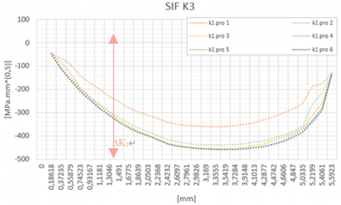
Figures 9, 10 and 11 represent the six contours of the KI, KII, and KIII stress intensity factors on the crack bottom when applying the nominal pressure (0.2MPa). These SIFs are displayed as in Figures.
Figures 9, 10, 11 and 12 illustrate the variation of $\frac{K_I}{\sigma(\pi a)^{0.5}}$, $\frac{K_{I I}}{\sigma(\pi a)^{0.5}}$ and $\frac{K_{I I I}}{\sigma(\pi a)^{0.5}}$.
Figure 9. SIFS (K1)
Figure 10. SIFS (K2)
Figure 11. SIFS (K3)
Figure 12. SIF Mode for KI, KII, and KIII
We notice that the exhaust manifold is subjected mainly to Mode I loading. In fact, KI has the maximum magnitude SIF ∆K1, followed by KIII and KII (∆K2, ∆K3)
This simulation evaluates the SIFs on the exterior surface by internal pressure; then, the SIFs were much higher and dominant for circumferential cracks than the longitudinal cracks under thermo-mechanical loads.
6.4 Fatigue life
In this study, fatigue failure was estimated using the Goodman method. It is a stress-based approach commonly used for predicting fatigue life in engineering applications. It takes into account both the alternating stress (σa) and the mean stress (σm) acting on a material, The mathematical expression for it is as follows: The mathematical expression for it is as follows [14]:
$\frac{\sigma_a}{\sigma_e}+\frac{\sigma_m}{\sigma_u}=1$
where,
σm: mean stress
σe: is the endurance fatigue limit,
σu: is the ultimate tensile strength,
σa: Tensile yield stress
The Goodman method is adopted for calculating theoretical fatigue life. Fatigue load is obtained from the condition of the stability test. Based on the load (0.2MPa) applied in the structural analysis,
The results obtained from the fatigue analysis using Ansys Workbench provide insights into the fatigue life of the exhaust manifold. They can be used to optimize its design and material properties to improve its durability and reliability.
Figure 13. Fatigue life of the exhaust manifold without fracture
Figure 14. Fatigue life of the exhaust manifold with fracture
Based on the illustration presented in Figure 13, it was observed that the exhaust manifold could last for a minimum of 11,686 cycles without any fractures, specifically in the exhaust bracket. However, the maximum lifecycle recorded is approximately 1 million cycles.
As shown in Figure 14, The exhaust manifold now has a reduced minimum fatigue life of 0 cycles, compared to its original minimum lifecycle without any cracks.
Table 3. Fatigue life
|
Fatigue Life |
Min [Cycle] |
Max [Cycle] |
|
Exhaust manifold without fracture |
11,686 |
1E6 |
|
Exhaust manifold with fracture |
0 |
1E6 |
The presence of a crack in the product significantly reduces its fatigue strength compared to the exhaust manifold without a crack, as shown in Table 3. The crack acts as a stress concentration point, intensifying localized stress and promoting crack growth. As a result, the product with a crack is expected to have a shorter fatigue life.
In This paper, we present an analysis of the crack failure using the FEM method; we have investigated the Stress Intensity Factor (SIF) using Finite Element Analysis for semi-elliptical fracture on the external surface, under variable loads, internal pressure, and temperature. The semi-elliptical fracture was specified using different aspects such as crack length and depth. As a result, the crack position becomes more significant as the crack length increases. Also, the SIF increases with increasing crack length; another remark is that SIFs in the longitudinal cracks were higher than the circumferential, finally, we noted that the presence of a crack in the product significantly reducing its fatigue strength compared to the exhaust manifold without a crack.
As a future investigation, we think that the integration of chemical reactions and the corrosion phenomena are critical to be included in this analysis to get a more significant result, considering the environment in which the exhaust manifold is located and predicting the behavior of the exhaust system under different conditions.
[1] Akhi, A.H., Dhar, A.S. (2021). Stress intensity factors for external corrosions and cracking of buried cast iron pipes. Engineering Fracture Mechanics, 250: 107778. https://doi.org/10.1016/j.engfracmech.2021.107778
[2] Khatri, K., Lal, A. (2018). Stochastic XFEM fracture and crack propagation behavior of an isotropic plate with hole emanating radial cracks subjected to various in-plane loadings. Mechanics of Advanced Materials and Structures, 25(9): 732-755. https://doi.org/10.1080/15376494.2017.1308599
[3] Fayed, A. (2017). Numerical analysis of mixed mode I/II stress intensity factors of edge slant cracked plates. Engineering Solid Mechanics, 5(1): 61-70. https://doi.org/10.5267/j.esm.2016.8.001
[4] Sharma, K., Singh, I.V., Mishra, B.K., Bhasin, V. (2014). Numerical modeling of part-through cracks in pipe and pipe bend using XFEM. Procedia Materials Science, 6: 72-79. https://doi.org/10.1016/j.mspro.2014.07.009
[5] Martins, R.F., Viegas, J.C., Cruz, H.J. (2011). Fatigue life assessment of an exhaust system for naval gas turbines. Procedia Engineering, 10: 2548-2553. https://doi.org/10.1016/j.proeng.2011.04.420
[6] Hidayanti, F., Adi, K.A.M., Wati, E.K. (2020). Developing racing exhaust system performance using computational fluid dynamics software. AIP Conference Proceedings, 2262: 030016. https://doi.org/10.1063/5.0016170
[7] Liu, H.J., Zhi, S.Y. (2021). Exhaust system Finite Element Analysis and optimizing design. Advanced Materials Research, 538-541: 590-594. https://doi.org/10.4028/www.scientific.net/AMR.538-541.590
[8] Lee, G.B., Park, S.H., Jang, Y.Y., Huh, N.S., Park, S.H., Park, N.H., Park, J. (2022). Development of automatic crack growth simulation program based on Finite Element Analysis. Applied Sciences, 12(6): 3075. https://doi.org/10.3390/app12063075
[9] Varun Ram, G., Nithesh Sharan, G., Praveen Kumar, T., Tanish, P. (2021). Design and analysis of exhaust system for ultra-fuel efficient vehicles. IOP Conference Series: Materials Science and Engineering, 1033: 012019. https://doi.org/10.1088/1757-899X/1033/1/012019
[10] Sasikumar, P., Sujatha, C., Chinnaraj, K. (2017). Transient fatigue analysis of exhaust system mounting brackets for commercial vehicle correlation. SAE Technical Paper. https://doi.org/10.4271/2017-01-1333
[11] Ahmad, F., Tomer, V., Kumar, A., Patil, P.P. (2016). FEA Simulation Based Thermo-mechanical Analysis of Tractor Exhaust Manifold. In: Mandal, D.K., Syan, C.S. (eds) CAD/CAM, Robotics and Factories of the Future. Lecture Notes in Mechanical Engineering. Springer, New Delhi. https://doi.org/10.1007/978-81-322-2740-3_18
[12] Salehnejada, M.A., Mohammadi, A., Rezaei, M., Ahangari, H. (2019). Cracking failure analysis of an engine exhaust manifold at high temperatures based on critical fracture toughness and FE simulation approach. Engineering Fracture Mechanics, 211: 125-136, https://doi.org/10.1016/j.engfracmech.2019.02.005
[13] Xie, M.J., Wang, Y.F., Xiong, W.N., Zhao, J.L., Pei, X.J. (2022). A crack propagation method for pipelines with interacting corrosion and crack defects. Sensors, 22(3): 986. https://doi.org/10.3390/s22030986
[14] Bader, Q., Kadum, E. (2014). Mean stress correction effects on the fatigue life behavior of steel alloys by using stress life approach theories. International Journal of Engineering & Technology IJET-IJENS, 14(4).