Muhammed A. Ibrahim*![]() | Mustafa Hussein Ibrahim
| Mustafa Hussein Ibrahim![]() | Salam Ibrahim Khather
| Salam Ibrahim Khather![]()
© 2023 IIETA. This article is published by IIETA and is licensed under the CC BY 4.0 license (http://creativecommons.org/licenses/by/4.0/).
OPEN ACCESS
The voltage output of an energy storage device utilized in electric vehicles (EVs) is modulated in response to the load, and the elevated voltage of the DC link poses challenges for vehicle engineers when integrating energy storage components with the traction drive system. DC-DC converters are commonly employed in electrical powertrain systems within industrial settings to facilitate the integration of various components. The Cuk converter is widely acknowledged as a viable alternative requiring thorough deliberation, including battery management systems (BMS) for EVs technology. This is because of a continuous flow of current in both the input and the output, and it has a high efficiency compared to the buck-boost topology. Additionally, there is a low ripple in the output load voltage. The present work uses an analysis, model, and control of the Cuk converter circuit using a hybrid fuzzy logic-based ant colony optimization (ACO) method. The transient response and the steady-state performance specifications are objective functions in the fuzzy controller design process. After a comprehensive evaluation of the obtained results, it was observed that the fuzzy-ACO controller successfully achieved the desired reference with reduced rise and settling time. This study implements modeling and controlling applications of the Cuk converter by utilizing the MATLAB/SIMULINK program. The proposed controller's effectiveness is demonstrated during load variations and changes in the reference voltage.
Cuk converter, intelligent control, fuzzy control, ant colony optimization, electric vehicle, switched-mode power supply
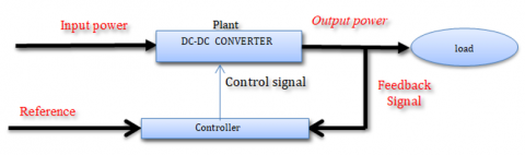
Switched-mode DC-DC converters have gained popularity in power electronics due to their high conversion efficiency and ability to provide an adjustable output voltage. Hence, the electronic device converters maintain a stable output voltage to the varying input voltage and load current. In order to satisfy the overall demand, it is recommended to employ sophisticated control techniques. In fact, there are numerous control methods available for dc-dc converters. The desire for a consistent control method demonstrating a high performance across all conditions is universal [1]. The general control system configuration is shown in Figure 1.
Figure 1. General control system configuration for DC-DC converter
It is worth mentioning that the Cuk converter possesses many advantageous characteristics. They include a negative output voltage, a low output current and switching ripple, capacitive energy transfer, and smooth input and output currents. Fourth-order characteristic's effects on dynamic response limit is a closed-loop system's bandwidth. Therefore, stability requires large energy capacitors to decouple input and output stages, complicating control and theoretical implementation [2, 3].
Furthermore, there are many studies on the Cuk converter in the literature; for example, Wong et al. [4] designed a neuro-fuzzy controller to regulate the Cuk converter output voltage by the PWM duty cycle. Instead of relying on expert knowledge, specific heuristic rules are generated using fuzzy variable membership functions adjusted by neural networks. Likewise, in the study of Yousefi et al. [5], a genetic algorithm (G.A.) and particle swarm optimization (PSO) are utilized to determine ideal gain coefficients in the design of the controller. It can achieve optimal dynamic performance for the Cuk converter [5]. Kushwaha and Narain [6] state space analysis (SSA) is used for model order reduction. As a result, the first small signal dynamic model for the Cuk converter with a fourth-order transfer function is developed. Consequently, the Pade approximation is then utilized to reduce the order of this transfer function from fourth to second. The parametric variation analysis of non-isolated CUK converters has been performed for constant voltage applications considering the inductor and capacitor's performance characteristics. It is to be added that the Cuk converter uses a capacitive energy transfer mechanism. If the boost capacitor varies slightly, the Cuk converter's overshoot and settling time may change considerably. The closed-loop Cuk converter has an efficiency of 98.69% [7]. The other attempt [8], two states of MOSFET, ON and OFF, are combined using the circuit averaging method with the state-space representation of both circuits to generate a single model. It is known as the average large signal model of the Cuk converter. Because the Cuk converter is primarily a Non-Minimal Phase (NMP) system, average modeling and tiny signal analysis are conducted to linearize the system. Creating a controller for it is a challenging task. Using a graphical loop shaping technique for the controller design of a Cuk converter. The loop shaping method is utilized for controller design, enhanced gain margin, and phase margin [9]. Research on renewable energy began with the goal of developing electric vehicles that function satisfactorily on paved roads in urban environments. Additionally, Electric vehicles have a restricted driving range, and mountainous terrain is not ideal for their performance. On roads and at high speeds, gasoline engines' performance is superior to diesel engines. Therefore, the output voltage was raised by Cuk converters to enable vehicles to travel further distances. Controllers are also utilized to improve converter output response when many dc-dc converters and modified Cuk converters are utilized in the system [10]. By contrast, to develop a P.V. A.C. module, a proposal was made to utilize a high static gain Cuk converter structure with switched inductors. Several topologies based on the traditional Cuk converter have been documented in the literature [11-13].
Determining the appropriate parameters for the fuzzy logic controller is challenging. It entails a significant time commitment. Due to their capacity to effectively address intricate problems, ant colony optimization (ACO) can be employed to select the optimal parameters of a fuzzy controller. As a consequence, the present study uses the Fuzzy Logic Controller, based on ant colony Optimization, to regulate the converter circuit's output voltage. The primary objective of this approach is to enhance the performance of the converter circuit's output.
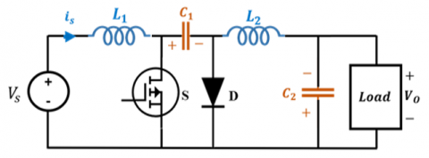
Cuk converters are electronic circuits designed to convert the input voltage typically in direct current (D.C.) form to the desired voltage levels at the output. Cuk converters are acquired through the sequential connection of boost and buck converters. The circuit diagram can be found in Figure 2 [14].
Figure 2. The circuit arrangement of the Cúk regulator
Continuous current flow at both the input and output of the circuit is one of the most significant benefits of this topology over other similar DC-to-DC converter topologies. As a result, the performance of the converter is outstanding. They control whether the switch (S) is in the state (1) or off state (0), bringing about the desired results of regulated output voltage and an optimized control approach. Figure 3(a) and Figure 3(b), respectively, illustrate the various modes of operation that the converter can utilize when it is in the on and the off states individually [2].
Figure 3. Equivalent circuits of the Cuk converter (a) On state, (b) Off state
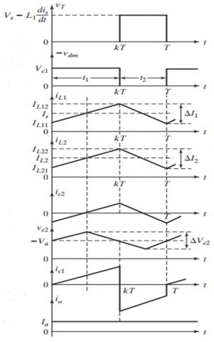
As can be seen in Figure 3, the converter circuit is divided into two distinct sections. When the transistor switch is closed during the on state, the current flowing through the inductor L1 increases. At the same time, the voltage from capacitor C1 applies a reverse bias to diode D1, which causes it to stop conducting and turn off. The energy stored in the capacitor C1 is released into the circuit formed by the load, the capacitors C1 and C2, and the load (Figure 3(a)). In the same way, in the Off state, the diode D1 is forward biased, and the capacitor C1 is charged through the input supply Vg, L1, and D1. This occurs when the input voltage is turned on and switch S is open. The load receives the energy stored in the inductor L2, which is then delivered. Synchronous switching action is produced by combining the diode D1 and the switch S as shown in Figure 3(b). The Cuk converter may accelerate the voltage depending on the duty cycle applied. Because the Cuk converter incorporates series inductors at both the input and output, it experiences far less current ripple in both circuits than other converters. The waveforms for steady-state voltages and currents are shown in Figure 4 for a continuous load current.
Figure 4. The waveforms for steady-state voltages and currents for the Cuk converter
The switch duty cycle can be used to get the formula for calculating the output voltage on average and key equations are described below [2, 15, 16].
Duty cycle,
$K=\frac{-V_0}{V_S-V_0}$ (1)
Output voltage,
$V_0=\frac{-k V_S}{1-k}$ (2)
Non-isolated Cuk converter design parameters and equations are given:
$L_1=\frac{-k V_S}{\left(\Delta I L_1\right) f_S}$ (3)
$L_2=\frac{(1-k) V_0}{\left(\Delta I L_2\right) f_S}$ (4)
$C_1=\frac{k}{\left(R f_S\right)\left(\frac{\Delta V_{C 1}}{V_0}\right)}$ (5)
$C_2=\frac{(1-k)}{\left(8 L_1 f_s^2\right)\left(\frac{\Delta V_{C 2}}{V_0}\right)}$ (6)
where, fs is the switching frequency, IL1 and IL2 are peak-to-peak ripple currents, VC1 and VC2 are voltage ripples, and D is the duty cycle. Table 1 shows the Cuk converter parameters.
Table 1. Parameter used in the Cuk converter
|
Output Power |
P0 |
500 W |
|
Output Voltage |
V0 |
12 V |
|
Input Voltage |
VS |
28 V |
|
Switching Frequency |
fS |
20kHz |
|
Inductance Values |
L1, L2 |
117 µH, 50.4 µH |
|
Capacitance Values |
C1, C2 |
1 mF, 3 mF |
The Cuk converter circuit is implemented in MATLAB/SIMULINK program with data gathered in Table 1. The output voltage response in the open loop condition is shown in Figure 5 for different duty cycle values in the converter switch state.
Figure 5. Open loop system response for different values of duty cycle (k=0.1, k=0.3, k=0.6)
From the previously mentioned characteristics and performances in the Cuk converter operating points and its nonlinearity due to switching. A high-precision controller should be designed to control the output voltage in various conditions.
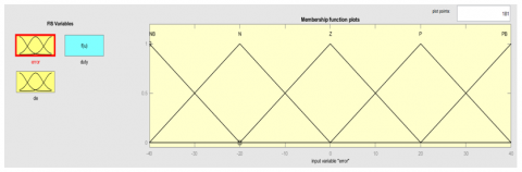
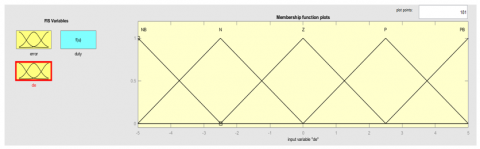
Fuzzy control is a feasible alternative for various complex control applications because it offers a straightforward approach to designing nonlinear controllers using heuristic information [17, 18]. This makes fuzzy control an appealing choice for many control problems. The error signal e(t) and the error change signal e(t) of the output voltage response have been designed as the inputs for the fuzzy logic controller so that they can be written down. The definitions of the linguistic variables are as follows: (N, NS, Z, P.S., P), where N denotes a negative value, N.S. denotes a negative value that is little, Z denotes zero, P.S. denotes a small positive value, and P denotes a positive value. As depicted in Figure 6, consideration is given to the triangular membership functions of the fuzzy logic controller.
Figure 6. Fuzzy controller membership function
ACO refers to a set of optimization techniques that are modeled on the activities that take place within an ant colony. The search for optimal solutions is performed by artificial "ants" moving across a parameter space representing all available solutions. An artificial colony of optimizers (ACO) is a group of software agents that work together to find optimal solutions to any given optimization challenge [19, 20]. The ACO algorithms are used to build the best fuzzy logic controller to search everywhere in the search space for the optimal gain settings for the fuzzy controller. A general representation of the topology of the fuzzy logic controller that employs ACO algorithms is shown in Figure 7. After the optimization method has been developed with the assistance of the MATLAB m-file application, it is linked with the system simulation software written in MATLAB/SIMULINK. This is done to evaluate the system's performance after each iteration of the optimization method. The tuning approach was used to manipulate the fuzzy inference system and scaling gains, run the simulation based on Simulink, check the performance of the simulation based on the results, and continuously modify the fuzzy inference system [21, 22].
Figure 7. Proposed system block diagram
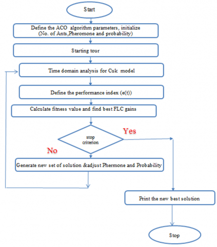
The MATLAB M-file has been utilized in the programming of the ACO method. This study uses the ACO algorithm to calculate the fuzzy controller gains during the system disruption. The error signal is passed on to the ACO algorithm. After that, it begins to adjust the values of the fuzzy gains to maintain the system performance intended by duty cycle (D) regulation. The proposed controller algorithm implementation is described in the flowchart in Figure 8.
Figure 8. Flowchat of the propsed fuzzy-ACO
The response of the output signal of the Cuk converter can offer valuable information regarding the efficacy and reliability of the controller's architecture. The subject undergoes a range of standardized assessments and protocols within a regulated setting to assess its efficacy. The MATLAB software incorporates the closed-loop control mechanism essential for the satisfactory operation of the Cuk Converter prototype. The graphical representation of the system is illustrated in Figure 9 below.
MATLAB/SIMULINK software is used for the various operating points in the Cuk converter control system in order to investigate the effectiveness of the methods that are intended to be used. Figure 10 displays the results of the set point tracking test, which shows that the output voltage response tracks the reference. The required voltage at constant set points of 20V, 40V, and 30V and at times t=0 s, t=0.5 s, and t=1 s, respectively, with a voltage error signal.
Figure 9. The closed-loop control system of the Cuk converter model
Figure 10. The load output voltage of the Cuk converter is at 20V, 40 V, and 30 V Setpoint
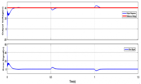
During steady operation, the proposed fuzzy controller based on ACO is validated by making a step change in the amount of load. This is done so that the antidisturbance capability of the controller can be tested. Figure 11 shows the simulation result test of the Cuk converter circuit performed at a voltage of 40 V. The load increased from fifty percent to seventy percent in half a second, then decreased to fifty percent in one second.
Figure 11. The load output voltage of the Cuk converter is at 40V with load disturbances
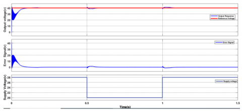
When designing the control system for a DC-DC converter system, external disturbances significantly impact a system's performance; therefore, it must consider this. In addition, the proposed controller is evaluated for supply voltage disturbances, as seen in Figure 12. The disturbance signal is input into the system at a rate of 0.5 s for a value of -30% and at a rate of 1 s for a value of +30%.
Figure 12. The load output voltage of the Cuk converter at supply voltage disturbances
The outcomes of the simulation have been presented. The findings above were employed to ascertain the efficacy and reliability of the fuzzy logic controller (FLC) utilizing ant colony optimization (ACO) controllers for the Cuk converter. A simulation is conducted to examine the relationship between the two variables. The controller in the system exhibited a notable degree of resilience in its response to various conditions, including start-up conditions, reference tracking conditions, supply disturbances, and load disturbance conditions. This conclusion is arrived at in all four potential outcomes. The controller exhibited a notable degree of resilience in managing supply disruptions.
DC-DC converters are commonly employed to facilitate the interface between various components within electrical powertrains in industrial applications. This study involves the utilization of MATLAB/SIMULINK to conduct dynamic analysis and modeling of the Cuk converter. The proposed circuit voltage response has been studied in different operating conditions. Using FLC based on ant colony optimization, the output voltage response of the Cuk converter circuit is regulated. ACO is used to identify the FLC gains to provide the best output performance. Method for overcoming the issue of trial and error when determining the FLC constant gains. The Cuk converter's output voltage has been evaluated with the feedback controller for different operating points, including reference tracking, load disturbances, and supply-side disturbances. Therefore, this proposed converter can be utilized in various industrial applications. Potential areas of future research in this field may involve investigating the concept of fuzzy gain scheduling control.
The authors wish to acknowledge the contributions of Nineveh University and University of Mosul in providing resources that have enhanced the overall quality of this work and made them accessible to the wider audience.
[1] Khather, S.I., Ibrahim, M.A. (2020). Modeling and simulation of SEPIC controlled converter using PID controller. International Journal of Power Electronics and Drive Systems, 11(2): 833. https://doi.org/10.11591/ijpeds.v11.i2.pp833-843
[2] Rashid, M.H., Rashid, M.H. (2011). Preface for Third Edition. Power Electronics Handbook, pp. xvii–xviii. https://doi.org/10.1016/b978-0-12-382036-5.00050-1
[3] Sutikno, T., Purnama, H.S., Aprilianto, R.A., Jusoh, A., Widodo, N.S., Santosa, B. (2022). Modernisation of DC-DC converter topologies for solar energy harvesting applications: A review. Indonesian Journal of Electrical Engineering and Computer Science, 28(3): 1845-1872. https://doi.org/10.11591/ijeecs.v28.i3.pp1845-1872
[4] Wong, L.K., Leung, F.H.F., Tam, P.K.S. (1995). A Neuro-Fuzzy controller applying to a Cuk converter. In Proceedings of IECON'95-21st Annual Conference on IEEE Industrial Electronics, pp. 446-450. https://doi.org/10.1109/IECON.1995.483450
[5] Yousefi, M.R., Emami, S.A., Eshtehardiha, S., Poudeh, M.B. (2008). Particle swarm optimization and genetic algorithm to optimizing the pole placement controller on Cuk converter. In 2008 IEEE 2nd International Power and Energy Conference, pp. 1461-1465. https://doi.org/10.1109/pecon.2008.4762707
[6] Kushwaha, B.K., Narain, A. (2012). Controller design for Cuk converter using model order reduction. In 2012 2nd International Conference on Power, Control and Embedded Systems, pp. 1-5. https://doi.org/10.1109/icpces.2012.6508134
[7] Singh, S.P., Singh, D.K., Kumar, H., Dwivedi, R. (2014). Designing and parametric variation of PI controller for Buck converter for constant voltage applications. International Journal of Engineering Trends and Technology, 13(4): 169-174. https://doi.org/10.14445/22315381/ijett-v13p236
[8] Mokal, B.P., Vadirajacharya, K. (2017). Extensive modeling of DC-DC Cuk converter operating in continuous conduction mode. In 2017 International Conference on Circuit, Power and Computing Technologies (ICCPCT), pp. 1-5. https://doi.org/10.1109/iccpct.2017.8074188
[9] Rayeen, Z., Bose, S., Dwivedi, P. (2018). Study of closed loop Cuk converter controlled by loop shaping method. In 2018 IEEE 13th international conference on industrial and information systems (ICIIS), pp. 442-447. https://doi.org/10.1109/iciinfs.2018.8721386
[10] Balachander, K., Amudha, A., Ramkumar, M.S., Emayavaramban, G., Divyapriy, S., Nagaveni, P. (2021). Design and analysis of modified CUK converter for electric hybrid vehicle. Materials Today: Proceedings, 45: 1691-1695. https://doi.org/10.1016/j.matpr.2020.08.566
[11] Algazar, M.M., Abd El-Halim, H., Salem, M.E.E.K. (2012). Maximum power point tracking using fuzzy logic control. International Journal of Electrical Power & Energy Systems, 39(1): 21-28. https://doi.org/10.1016/j.ijepes.2011.12.006
[12] Chen, Z. (2012). PI and sliding mode control of a Cuk converter. IEEE Transactions on Power Electronics, 27(8): 3695-3703. https://doi.org/10.1109/tpel.2012.2183891
[13] Raju, D., Rajan, S.R. (2013). Simulation and hardware implementa tion of change in conductance MPPT controller for a solar photo voltaic system using Cuk converter. International Journal of Res earch in Engineering and Technology, 2(7): 188-195. https://doi.org/10.15623/ijret.2013.0207025
[14] Karaarslan, A. (2018). Modeling and performance analysis of cuk converter using PI and OCC method. International Journal on Technical and Physical Problems of Engineering, 10(3): 1-5.
[15] Utomo, W.M., Isa, N.A.A., Bakar, A.A., Gani, A.F.H.A., Prasetyo, B.E., Elmunsyah, H., Buswig, Y.M.Y. (2020). Voltage tracking of bridgeless PFC cuk converter using PI controller. International Journal of Power Electronics and Drive Systems, 11(1): 367. https://doi.org/10.11591/ijpeds.v11.i1.pp367-373
[16] Rashid, M.A.Z.A., Ponniran, A., Noor, M.K.R., Jumadril, J.N., Yatim, M.H., Kasiran, A.N. (2019). Optimization of PFC cuk converter parameters design for minimization of THD and voltage ripple. International Journal of Power Electronics and Drive System (IJPEDS), 10(1): 514-521. https://doi.org/10.11591/ijpeds.v10.i1.pp514-521
[17] Yurkovich, S., Passino, K.M. (1999). A laboratory course on fuzzy control. IEEE Transactions on Education, 42(1): 15-21. https://doi.org/10.1109/13.746327
[18] Al-Thahab, O.Q.J., Hasoony, A.S., Alkhafaji, A.S. (2020). Sixteen level power factor correction by using arduino microcontroller based fuzzy idea. Indonesian Journal of Electrical Engineering and Computer Science, 17(1): 156-165. https://doi.org/10.11591/ijeecs.v17.i1.pp156-165
[19] Dorigo, M., Birattari, M., Stutzle, T. (2006). Ant colony optimization. IEEE Computational Intelligence Magazine, 1(4): 28-39. https://doi.org/10.1109/ci-m.2006.248054
[20] Baocheng, W., Tiane, W., Zenghui, W. (2012). The implementation of parallel ant colony optimization algorithm based on matlab. In 2012 Third Global Congress on Intelligent Systems, pp. 27-29. https://doi.org/10.1109/gcis.2012.62
[21] Ahmad, A.H., Sultan, N.S. (2014). Design and implementation of controlled Zeta Converter power supply. American Journal of Electrical and Electronic Engineering, 2(3): 121-128. https://doi.org/10.12691/ajeee-2-3-10
[22] Khan, S., Abdulazeez, S.F., Adetunji, L.W., Alam, A.Z., Salami, M.J.E., Hameed, S.A., Islam, M.R. (2008). Design and implementation of an optimal fuzzy logic controller using genetic algorithm. Journal of Computer Science, 4(10): 799–806. https://doi.org/10.3844/jcssp.2008.799.806