Arckarakit Chaithanakulwat![]() | Nuttee Thungsuk* | Teerawut Savangboon | Somchai Ngao-Ngam | Phatcharaphong Kanharin | Nikom Kanjak | Thaweesak Tanaram
| Nuttee Thungsuk* | Teerawut Savangboon | Somchai Ngao-Ngam | Phatcharaphong Kanharin | Nikom Kanjak | Thaweesak Tanaram
© 2023 IIETA. This article is published by IIETA and is licensed under the CC BY 4.0 license (http://creativecommons.org/licenses/by/4.0/).
OPEN ACCESS
Fixed-speed wind turbines for generating electricity are also important because they are clean energy and do not pollute the environment. Developing maximum wind energy tracking and increasing DC voltage to optimal values is also an important factor designers must consider so that the power from generators connected to wind turbines can function efficiently. Therefore, in this researcher paper proposed a single-channel dc/dc boost converter control, three forms of algorithms consisting of neural networks, fuzzy algorithms and PID algorithms. The purpose of bringing these algorithms controlled because they wanted to compare the response and voltage control performance of the single-channel DC/DC boost converter to be associated with a three-phase inverter that controls PWM signal modulation with space vector technique. However, the principles and methodologies in this article are presented to simulate the algorithmic response using the MATLAB/Simulink program and compare it with the prototype mechanism. A comparison of the response performance and voltage regulation of the single-channel DC/DC boost converter showed that the three algorithms have different advantages and disadvantages but can be used together to achieve high efficiency.
single-channel, DC/DC boost converter, artificial neural networks, fuzzy logic, PID controllers, wind turbines, clean energy, MATLAB/Simulink
Today, many countries around the world rely heavily on alternative energy such as solar, wind, and ocean wave energy. Because the energy mentioned above is clean energy that does not pollute the environment and the humanity of the earth. Wind turbines are alternative energy that uses equipment as simple and cumbersome as solar panels with complex and costly manufacturing processes. However, the development of wind turbines has started to range from a few kilowatts for residential or commercial use to several megawatts in large wind farms. For small to medium-sized wind turbines, they normally have a rating below 300 kW and can be installed at home. Farms and businesses to compensate for utility energy consumption. Small wind power units can be combined with other power sources. Such as solar panels and diesel generators to create a standalone and grid-connected for use in remote areas. However, wind turbines are currently divided into two characteristics: fixed-speed wind turbines and variable-speed wind turbines. Constant speed wind turbines rotate at an almost constant speed, which is determined by the gear ratio, grid frequency and number of terminals of the generator maximum power generation efficiency is achieved only as required. The efficiency of the system decreases with the wind speed that is skewed on the plot [1]. However, wind turbines are protected by aerodynamic control of the propellers so as not to cause possible damage from strong gusts of wind. This constant-speed turbine generates highly volatile output power, causing the load associated with the system to be affected by the power generation system. Therefore, this type of turbine must have a strong mechanical design to absorb high mechanical stress. Conversely, wind turbines, variable speeds, energy conversions achieve maximum efficiency. Because the ratio of tip speed, which is the ratio of the tip speed of the propeller to the wind speed, is optimal, the maximum power generation efficiency is achieved at different wind speeds.
Nevertheless, for this research to determine the general properties of wind energy conversion systems (WECS), energy conversions will only use squirrel cage induction generator (SCIG) based on existing equipment. However, this WECS determined that the rotation speed is based on the number of poles of the stator winding. For a four-pole generator at a frequency of 50 Hz, the generator operates at speeds slightly higher than 1500 rpm at different wind speeds, causing the generator speed to vary by 1% of the rated speed.
For power converters widely used in constant-speed WECS, this converter is used to reduce inflow current and torque changes during start-up [2]. In this research, the WECS AC voltage regulator topology has the function of helping wind turbines start smoothly by reducing current flow and mechanical stress. Ordinarily, after the system starts working, the AC voltage regulator is short-circuited by the bypass switch, which reduces the power loss of the controlled device. For SCRs, the output voltage of the controller can be adjusted from zero to the maximum voltage, which effectively reduces the starting current of the system.
Similarly, the single-channel DC/DC boost converter is one of the converter topologies that is often chosen in wind energy conversion systems [3]. The converter is placed between the rectifier, the diode, and the inverter of the power conversion system. The boost converter performs two main functions, consisting of tracking the maximum energy from the wind and increasing the DC voltage to the optimum value. However, for inverters, it has the function of facilitating the capture of maximum energy from the wind at all wind speeds.
As explained, fixed speed wind turbines have some limitations in the gearbox, but they also have a positive effect on generators because wind turbines that vary in speed are often used in conjunction with synchronous generators. Similarly, considering the disadvantages, it is found that controlling the maximum power of the generator obtained from the control wind turbine is quite difficult. Based on the reasons explained, the researchers hypothesized the study and research for the principle of maximum power tracking control of generators and voltage control of DC/DC boost converter circuits using ANNC, FLC, and PID controller algorithms. However, for this research paper, the focus is on tracking the maximum power from the wind of wind turbine 2 MW and increasing the DC voltage to the appropriate value. For tracking wind maximum power and increasing DC voltage, three controlled forms of algorithms are used to compare the response and voltage control performance of the single-channel DC/DC boost converter. As a result of using the three control algorithms, both parts were found to have different advantages and disadvantages. However, if the three algorithms are integrated together, it will be more effective. However, for the rest of the topics, this article consists of the second part proposed scheme and related principles, and implementation described, and the third part is three. Results and discussion consist of simulation results and experiments. Finally, the part five conclusion.
In this section, we describe the details and relevant principles of the research presented. Considering Figure 1, in the first section on the left, it is found that it is the part of the initial set of powers that comprises wind turbines, gear blocks (GB) and generators (SCIG) with rotors are squirrel cage type. When the generator produces AC voltage, it passes through the mechanism of the full wave rectifier (REC) that filters the ripples to achieve a DC voltage with minimal ripples. However, for the second part, there will be an important component of the research article topic: single-channel DC/DC boost converter with switch device control (MOSFET) with three forms of control algorithms consisting of: artificial neural networks controller (ANNC), fuzzy logic controller (FLC), and PID controller (PIDC). This DC/DC boost converter controls the DC voltage and undergoes ripple filtration again. For constant voltage control, the principle of output voltage detection at the link point (DC-Bus) is used before entering the three-phase inverter. For inverters, it is the third segment that uses the principle of switching device operation control (IGBT) with the principle of SVPWM closed loop speed control and contains algorithmic ANNC, FLC, and PID controller. Consequently, the Induction motor (SCIM) is therefore loaded to test the response and voltage control performance of the single-channel DC/DC boost converter. There are three forms of controlled algorithms based on the proposed objectives of this research paper.
Figure 1. Proposed mechanism of the single-channel converter DC/DC boost
The next section discusses the mathematical principles involved in the research, including the single-channel DC/DC boost converter and the principle of the algorithmic ANNC, FLC, and PID controller. Notwithstanding, the simulation results are compared with the prototype mechanism produced, in order to verify the results and verify their validity for conclusions.
2.1 Wind turbine blades
Wind turbine blades are the dominant and important components of wind turbines. It is also the main mechanism for the most important operation of energy conversion with the process of converting wind kinetic energy into rotary mechanical energy. Wind turbine blades have evolved in aerodynamic design and materials from very early wind turbines. Modern wind turbine blades are usually made of aluminum, fiberglass or carbon fiber composites that provide a high ratio of strength to weight required. Generally, for a given wind turbine blade, the lifting force (Fw) can be adjusted to the degree of angle. When this angle is equal to zero, that is, the absence of lifting force or torque that causes the turbine blades to rotate. Thus, the power of air masses flowing at speed (vw) through cross-sectional space (A) can be calculated by
$P_w=\frac{1}{2} \rho A v_w^3$ (1)
Eq. (1), which ρ is the density of air in kg/m3, A is the sweeping area in m2 and vw is the wind speed in m/s. The density of air ρ is an element of air pressure and air temperature. Wind energy captured by wind turbine blades and converted into mechanical energy can be calculated by
$P_M=\frac{1}{2} \rho A v_w^3 C_p$ (2)
where, Cp is the power coefficient of the wind turbine blades. According to the Betz limit, with today's technology, the energy coefficient of modern turbines usually ranges from 0.2 to 0.5, which performs the function of rotation, speed and number of wind turbine blades. The energy produced is 2 MW at a wind speed of 12 m/s, and the air density ρ = 1.225 kg/m3. However, from Eq. (2) in the increase in energy captured by wind turbines, there are three possibilities: wind speed vw, Cp energy coefficient and sweep area A. Based on the Eqns. (1)-(2), wind turbines can be designed with a larger sweeping area to capture more energy. Depending on the area A=πl2, where l is the length of the wind turbine blades designed by the manufacturer in each model. Increasing the length of the wind turbine blades has the effect of squaring in the sweeping area and capturing energy. However, for this research, the wind turbines used were designed by manufacturers that improved the energy coefficients of turbine blades according to aerodynamics in accordance with international standards.
2.2 Induction generator models
The classification of inductions applied to generators in wind turbine systems is divided into two types: double-fed induction generators. (DFIGs) and squirrel cage induction generators (SCIGs) both generators have the same stators but only different rotor structures. However, for this research paper, SCIG type rotors are used, with structures consisting of laminated cores and rotor bars. The rotor bar is embedded inside the rotor. When the stator coil is connected to a three-phase power supply, it creates a rotating magnetic field in the air gap. Because the rotor band shorts circuits, the voltage of the induction rotor produces a rotor current, which reacts with the rotating field to produce an electromagnetic field.
Nevertheless, for writing dynamic models commonly used for induction generators, they are divided into two. Based on space vector theory, it is a dq-axis model derived from vector model space. This space vector model has a compact mathematical expression and a single equivalent circuit. Instead, it uses variables that are both real and imaginary. Whereas the dq-frame model consists of two equivalent circuits for each axis. These models have a convenient relationship for analyzing the temporal performance and static state of the induction generator.
2.3 Space-vector model
The development of the induction generator space vector model is based on two hypothetical points: the induction generator is symmetrical in structure and three-phase equilibrium. The second point is that the magnetic core of the stator and rotor will be linear with a slight loss in the core. This induction generator space vector model generally consists of three sets of equations: the voltage equation, the flux link equation, and the motion equation [4, 5]. The voltage equations for the stator and rotor of the generator in the frame of reference are written as equations to be obtained.
$\vec{v}_s=R_s \vec{i}_s+p \vec{\lambda}_s+j \omega \vec{\lambda}_s$ (3)
$\vec{v}_r=R_r \vec{i}_r+p \vec{\lambda}_r+j\left(\omega-\omega_r\right) \vec{\lambda}_r$ (4)
where, $\vec{v}_s, \vec{v}_r$ are stator and rotor voltage vectors $(\mathrm{V}), \vec{\imath}_s, \vec{\imath}_r$ are stator and rotor current vectors (A), $\vec{\lambda}_s, \vec{\lambda}_r$ are stator and rotor flux-linkage vectors $(\mathrm{wb}), R_s, R_r$ are stator and rotor winding resistances $(\Omega), \omega$ is the rotating speed of the arbitrary reference frame $(\mathrm{rad} / \mathrm{s}), \omega_r$ is rotor electrical angular speed $(\mathrm{rad} / \mathrm{s}), p$ is derivative operator $(p=d / d t)$. The terms $j \omega \vec{\lambda}_s$ and $j\left(\omega-\omega_r\right) \vec{\lambda}_r$ on the right-hand side of Eqns. (3) and (4) are referred to as speed voltages, which are induced by the rotation of the reference frame at the arbitrary speed of a $\omega$. Similarly, an equation for the stator and rotor flux linkages can be written a
$\vec{\lambda}_s=\left(L_{l s}+L_m\right) \vec{i}_s+L_m \vec{i}_r=L_s \vec{i}_s+L_m \vec{i}_r$ (5)
$\vec{\lambda}_r=\left(L_{l r}+L_m\right) \vec{i}_r+L_m \vec{i}_s=L_r \vec{i}_r+L_m \vec{i}_s$ (6)
where, Ls= Lls + Lm is stator self-inductance (H), Lr= Llr + Lm is rotor self-inductance (H), Lls + Llr is stator and rotor leakage inductance (H), Lm is magnetizing inductance (H). All the rotor-side parameters and variables, such as Rr, Llr, $\vec{l}_r$ and $\vec{\lambda}_r$, in the above equations are referred to the stator side. The third set of equations is the equation of motion, which describes the dynamics and behavior of the mechanical velocity of the rotor in terms of mechanics and electromagnetism torque as
$\vec{v}_s=v_{d s}+j v_{q s} ;\quad \vec{i}_s=i_{d s}+j i_{q s} ; \quad \vec{\lambda}_s=\lambda_{d s}+j \lambda_{q s}$ (7)
$J \frac{d \omega_m}{d t}=T_e-T_m$ (8)
$T_e=\frac{3 P}{2} \operatorname{Re}\left(j \vec{\lambda}_s \vec{i}_s^*\right)=-\frac{3 P}{2} \operatorname{Re}\left(j \vec{\lambda}_r \vec{i}_r^*\right)$ (9)
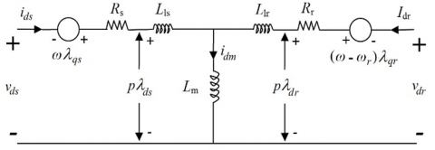
where, J is the moment of inertia of the rotor (kgm2), P is the number of pole pairs, Tm is the mechanical torque from the generator shaft (N•m), Te electromagnetic torque (N•m), ωm is the rotor mechanical speed, ωm=ωr/P (rad/sec). The above equation is a space vector model of an induction generator, which shows an equivalent circuit, as in Figure 2, the generator model is in an arbitrary frame of reference, rotating in space at an arbitrary speed ω.
Figure 2. Space-vector equivalent circuit of an induction generator
From the space vector model of the induction generator, as shown in Figure 2, the principle of motor operation is applied by considering the direction of the stator current flowing into the stator. This convention is widely accepted since inductors are mainly used as motors. However, if there is no loss of space vector models, these equations can be used to model inductors, whether motors or generators.
2.4 Dq reference frame model
This topic describes the dq-axis model of an induction generator by decomposing space vectors in the components of the d-axes and q-axes, as shown in Figure 3.
(a) d-axis circuit
(b) q-axis circuit
Figure 3. Induction generator dq-axis model in the reference frame.
Figure 3 writes the voltage equations of the stator and rotor as equations as
$\vec{v}_s=v_{d s}+j v_{q s} ;\quad \vec{i}_s=i_{d s}+j i_{q s} ; \quad \vec{\lambda}_s=\lambda_{d s}+j \lambda_{q s}$ (10)
$\vec{v}_r=v_{d r}+j v_{q r} ; \quad\vec{i}_r=i_{d r}+j i_{q r} ; \quad\vec{\lambda}_r=\lambda_{d r}+j \lambda_{q r}$ (11)
Moreover, the groups the real and imaginary components as
$v_{d s}=R_s i_{d s}+p \lambda_{d s}-\omega \lambda_{q s}$ (12)
$v_{q s}=R_s i_{q s}+p \lambda_{q s}+\omega \lambda_{d s}$ (13)
$v_{d r}=R_r i_{d r}+p \lambda_{d r}-\left(\omega-\omega_r\right) \lambda_{q r}$ (14)
$v_{q r}=R_r i_{q r}+p \lambda_{q r}+\left(\omega-\omega_r\right) \lambda_{d r}$ (15)
Similarly, substituting Eqns. (10) and (11) into Eqns. (3) and (4), the dq-axis flux linkages are obtained:
$\lambda_{d s}=\left(L_{l s}+L_m\right) i_{d s}+L_m i_{d r}=L_s i_{d s}+L_m i_{d r}$ (16)
$\lambda_{q s}=\left(L_{l s}+L_m\right) i_{q s}+L_m i_{q r}=L_s i_{q s}+L_m i_{q r}$ (17)
$\lambda_{d r}=\left(L_{l r}+L_m\right) i_{d r}+L_m i_{d s}=L_r i_{d r}+L_m i_{d s}$ (18)
$\lambda_{q r}=\left(L_{l r}+L_m\right) i_{q r}+L_m i_{q s}=L_r i_{q r}+L_m i_{q s}$ (19)
The electromagnetic torque Te in Eq. (9) can be represented by dq-axis flux, linkage and current are the same. However, mathematical manipulation of several expressions for torque can be obtained. The most commonly used expressions are as follows:
$T_e=\left\{\begin{array}{l}\frac{3 P}{2}\left(i_{q s} \lambda_{d s}-i_{d s} \lambda_{q s}\right) \quad (a)\\ \frac{3 P L_m}{2}\left(i_{q s} i_{d r}-i_{d s} i_{q r}\right) \quad (b)\\ \frac{3 P L_m}{2 L_r}\left(i_{q s} \lambda_{d r}-i_{d s} \lambda_{q r}\right)\quad (c)\end{array}\right.$ (20)
However, from Eqns. (10) to (20) together with equations of motion (8)-(9) instead of axes. dq. The form of the induction generator in the frame of reference and related. The dq-axis equivalent circuit is shown in Figure 3. To obtain a dq-axis model in synchronous and stationary reference frames, the speed of the W reference frame can be set to the synchronous frequency (stator) WS of the generator and zero, respectively.
2.5 Single-channel boost converter
A typical circuit diagram for a single-channel boost converter, as shown in Figure 4, would show that a boost converter is a power converter with a DC voltage output rather than an input. This single-channel boost converter circuit consists of switches, diodes, inductors, and filters, namely capacitors. For capacitors, the output filter must be sufficiently large, and the output voltage of the converter must be free of ripples.
Figure 4 briefly describes the principle of operation, namely when the switch is on. The diode has a reverse bias, and the output is equal to the input, since the circuit is turned on. When the switch is turned off the diode is forward biased, and the energy stored in the inductor is released by flowing through the diode. In this case, the output voltage is the sum of the input voltage and the inductor voltage [6-9], resulting in the output voltage of the converter being higher than the input voltage.
Figure 4. The single-channel boost converter
However, the operation of this converter will depend on the continuation of the induction current. As for the operation of the converter, it can be divided into two modes of operation, consisting of continuous-current mode (CCM) and discontinuous-current mode (DCM), and it is found that when the boost converter is operates in CCM, the inductive current does not fall to zero.
In steady-state operation of the converter, the integral of the induction voltage. Over time period (ts) it must be zero, meaning that the average voltage across the inductor must be greater than the interval to zero and write the basic equations of the converter as
$V_i t_{\text {on }}=\left(V_o-V_i\right) t_{\text {off }}$ (21)
from which
$\frac{V_o}{V_i}=\frac{1}{1-D} \quad$ for $0 \leq D<0$ (22)
where, D is the duty cycle converter defined by D=ton/ts, ts is the switching period, and the ton and toff are the switch turn-on (ton) and turn-off (toff) respectively. The above expression indicates that the output voltage of the converter is always higher than the input voltage.
The relationship between the converter input current and output current can be derived from ViIi=VoIo from which
$\frac{I_o}{I_i}=1-D \quad for \quad 0 \leq D< 1$ (23)
However, for calculating ripple currents in inductors and designing inductors and capacitors is not explained at this research article.
2.6 The control algorithm of the single-channel boost converter
2.6.1 Artificial neural networks controller
The relationship between machine learning and neural networks replaces the model with explanatory learning rules, the learning rules for neural networks can be found in Figure 5.
Figure 5. The relationship between machine learning and the neural network
However, learning something about the human brain will be a way of retaining knowledge. Although they both store their data with different mechanisms, the computer stores the data according to the location of the memory. While the human brain uses a method of altering neuronal relationships, in which the neurons themselves do not have the ability to store them, they use the method of transmitting signals from one place of the neuron to the other. The human brain is therefore a gigantic network of these neurons, and the relationships of neurons are therefore applied in a specific information model called the neural network [10-13]. Similarly, it can be further explained using the mechanisms of neural networks for better understanding by considering them as nodes of conditions obtained as three inputs, as shown in Figure 6.
Figure 6. A node that receives three inputs
Figure 6 shows that the circle and arrows of the figure show the nodes and flows of x1, x2, and x3 signals, respectively, which are input signals. Likewise, w1, w2 and w3 are the weight of the corresponding signals, and finally, b is the bias, which is another relevant factor of data storage, which is the information of the neural net that is stored in the form of weights and bias. However, the input signal from the outside is multiplied by the weight before that to the node. When a weighted signal is collected at the node [14-17]. These values are added as weighted sums. This weighted sum is written as
$v=\left(w_1 \times x_1\right)+\left(w_2 \times x_2\right)+\left(w_3 \times x_3\right)+b$ (24)
The equation of the weighted sum can be written with matrices as
$v=w x+b$ (25)
where, w and x are defined as
$w=\left[\begin{array}{lll}w_1 & w_2 & w_3\end{array}\right] \quad x=\left[\begin{array}{l}x_1 \\ x_2 \\ x_3\end{array}\right]$ (26)
Finally, the node enters the weighted sum into its activation and output function [18]. The activation function determines the behavior of the node.
As part of the neural network design of the single-channel boost converter, for this research, a mathematical model by the MATLAB/Simulink program was used to create a feed forward neural network control block. This control block uses coaching by entering the input conditions of dc voltage, DC voltage output and output current, defined as duty cycle value [19-21]. However, for better understanding, it is shown as a model used in the coaching of neural networks as shown in Figure 7.
In Figure 7, this neural network model defines the input as a three-parameter value consisting of voltage, current, and power. The second part, the Hidden SCBC section, this procedure contains 15 sets, which is a machine learning process, and the tangent sigmoid transfer function, which is a function that accepts both positive and negative input parameters. The third part is a linear output transfer function with 1 machine learning process used for linear estimation. However, when modeling neural networks neatly. The next step will be the process of bringing input data sets and target datasets to be coached to the neural network. This network coaching network is divided into 3 components with a 70% coaching section, 15% monitoring part, 15% test part. Nevertheless, weights and bias are adjusted during coaching to reduce neural network errors.
Figure 7. Neural network models used in single-channel boost converter coaching
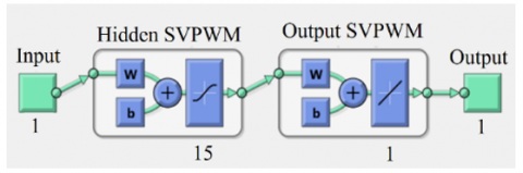
Figure 8. Neural network models used in space vector pulse width modulation coaching
Similarly, for a three-phase inverter. Determination of the input voltage of the load to control the operation of the speed of the three-phase induction motor, which is the output voltage of the three-phase inverter. Determining the output of a neural network is the modulation index value and frequency of the model in coaching, as shown in Figure 8.
Consequently, from both models of neural networks, there are multiple layers of conditions. The first layer is the part of the input, which receives the parameter values, variables and conditions. The second layer is the hidden section. This layer contains 15 sets and has a tangent sigmoid transfer function, in which this function receives positive and negative input signals. The third layer is the output part, there is a certain amount, the neural has a linear transfer function. However, once the neural network model is defined, the input dataset and target dataset will be used to further coach the neural network.
2.6.2 Fuzzy logic controller
In engineering, vague fuzzy logic and reasoning algorithms are used to control systems. Using the fuzzy logic algorithm to control the output voltage of the single-channel boost converter, there is a basis for the processing of the fuzzy logic algorithm as shown in Figure 9. For this research, fuzzy logic algorithms were used to detect changes in output voltage and current and process them to generate a single-channel boost converter control duty signal [22-24]. However, for the fuzzifier part, it defines variables and imports voltage and output current change data and duty cycle values.
Figure 9. Fuzzy logic algorithm diagram
However, for fuzzy conditions, the logic algorithm to control the duty cycle can be divided into five variables comprising NB (Negative Big), NS (Negative Small), ZE (Zero), PS (Positive Small) and PB (Positive Big) [25-28]. The single-channel boost converter control uses the basic conditions voltage variable, current variable input and duty cycle output as shown in Figure 10.
Figure 10. Control of the basic conditions of fuzzy logic
2.6.3 PID controller
This topic explains the basic application of PID control algorithms for Single-Channel Boost Converter and controls the angular position of three-phase induction motor drive [29-31]. However, this research uses the following two basic command transfer functions as
$\frac{Y(s)}{U(s)}=\frac{b}{s(s+a)}$ (27)
An ideal PID controller has the transfer function.
$C(s)=K_c\left(1+\frac{1}{\tau_1 s}+\tau_D s\right)$ (28)
where, Kc is the proportional gain, τ1 is the integral time constant and τD is the derivative gain. We rewrite the PID controller given in (30) into the transfer function form.
$C(s)=\frac{c_2 s^2+c_1 s+c_0}{s}$ (29)
By comparing (30) with (31), we have the relationships,
$K_c=c_1 ; \quad \tau_1=\frac{c_1}{c_0} ; \quad \tau_D=\frac{c_2}{c_1}$ (30)
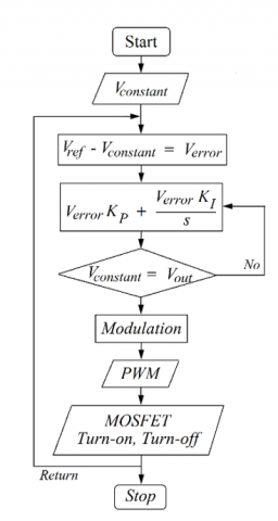
Consequently, in the design of the single-channel boost converter and controls the angular position of the three-phase induction motor. The first step is to find the parameters in (31), and then convert them to the PID controller using the necessary parameters in the next execution step [32]. However, this research paper summarizes the application of PID algorithms as Flowchart diagrams as shown in Figure 11 and Figure 12 respectively.
Figure 11. Diagram of single-channel boost converter with PID controlling
Figure 12. Diagram of SVPWM with PID controlling
Present the above research, literature, and principles. This research has produced prototypes starting from the design of the voltage regulator circuit of wind turbines, single-channel boost converter circuits, three-phase inverters connecting induction motor. This prototype consists of DC voltage capacitors, current filter inductors, MOSFET circuits, gate drive circuits, delay circuits, current detection circuits, voltage detection circuits, and three-phase inverter designs. Consequently, write commands for processing with mathematical model functions of the MATLAB/Simulink program into the microcontroller. The following sections will present the results of the prototype compared to the MATLAB/ Simulink program. It also analyzes the results for further development and application.
Figure 13 is a component of the prototype mechanism used for this research, for the experiment to be shown in the following section.
Figure 13. Components of the prototype mechanism
Nevertheless, the following sections are simulated using mathematical models of the MATLAB/Simulink program to compare with prototype mechanism experiments produced to control the single-channel DC/DC boost converter circuit with artificial neural networks, fuzzy logic and PID controllers [33].
Moreover, simulation and experimental topics will include heuristic analysis of ANNC, FLC, PIDC algorithms when the input voltage from wind turbines changes. The next topic was the simulation and experimentation of the prototype mechanism driving the three-phase induction motor to compare the response and voltage regulation performance of the algorithms used to control the three. The final topic is to simulate and experiment with the speed control prototype mechanism of a three-phase electric motor to compare the performance of the algorithm, with the following details.
(a) Simulation and experimentation ANNC algorithms
(b) Simulation and experimentation FLC algorithms
(c) Simulation and experimentation PIDC algorithms
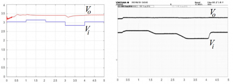
Figure 14. The control voltage regulation of single-channel DC/DC boost converter
Based on Figure 14 (a), (b) and (c), the prototype mechanism of the single-channel DC/DC boost converter is to experimentation the response and voltage regulation performance of the mechanism, which uses the control of the ANNC, FLC, PIDC algorithms [34]. However, compared to mathematical simulations with the MATLAB/Simulink program, it was found that the FLC algorithm can best regulate voltage and the next sequence is the ANNC algorithm. Similarly, for PIDC, it regulates pressure just as well as both algorithms. But the analysis revealed that ANNC, FLC, and PIDC, if written with more granular input conditions, could cause more constant voltage regulation. However, it is also important to properly design the inductor and capacitor to achieve minimal ripples as well [34].
(a) The voltage and current of the mechanism of ANNC
(b) The voltage and current of the mechanism of FLC
(c) The voltage and current of the mechanism of PIDC
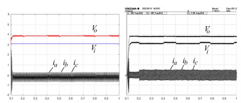
Figure 15. Single channel DC/DC boost converter load supply
Similarly, when the prototype mechanism of the single-channel DC/DC boost converter is applied in conjunction with the three-phase inverter and driven three-phase induction motor. Experiments comparing the response and performance of the DC/DC boost converter showed that even with the input voltage constantly changing, the FLC algorithm was able to control the mechanism to have the best constant and stable voltage. When considering ANNC and PIDC, it was found that ANNC was able to regulate the voltage of the mechanism with a slight difference, as shown in Figure 15 (a), (b) and (c).
Moreover, from Figure 15 (a), (b) and (c). When considering the output current of the three-phase inverter and the input current of the three-phase induction motor. When the motor was connected with an electromagnetic break to Based on Figure 14 (a), (b) and (c), the prototype mechanism of the single-channel DC/DC boost converter is to experimentation the response and voltage regulation performance of the mechanism, which uses the control of the ANNC, FLC, PIDC algorithms [34]. a load equal to 5 Nm, it was found that the currents of phases a, b, and c had almost the same flow current in all three phases. However, for a three-phase induction motor with a squirrel cage induction motor (SCIM) type rotor, if the parameter design has the same impedance per phase, it results in the same flow in each phase.
(a) The step load from 1 Nm to 5 Nm of ANNC
(b) The step load from 1 Nm to 5 Nm of FLC
(c) The step load from 1 Nm to 5 Nm of PIDC
Figure 16. The experiment increases the load 1-5 Nm
The following topics are experiments in bringing the mechanisms of the single-channel DC/DC boost converter and three-phase inverter to control the speed of the squirrel cage induction motor (SCIM) to a constant 1500 rpm. From Figure 16 (a), (b) and (c), once the speed of SCIM is controlled to be constant, the experiment increases the load from 1 Nm to 5 Nm respectively using electromagnetic break. Based on experiments of speed control with an ANNC, FLC, and PIDC algorithm of three-phase inverter, and at the same time the mechanism of the single-channel DC/DC boost converter controlled with an ANNC, FLC, and PIDC algorithm, it was found that the FLC algorithm can control voltage and speed in an astonishing and optimal way. However, for algorithms, ANNC and PIDC can control voltage and speed very well, although they are not equal to FLC. Moreover, if one considers the input current at the three-phase induction motor, it will be found that in the range of increasing the load to the FCL algorithm steps will generate more surge currents than the ANNC and PIDC algorithms.
Notwithstanding, the resulting surge current will not be much, but it is prudent to be careful with the equipment used for the mechanisms created. Consequently, interested parties and researchers should analyze and study additional causes for further development before applying them in the future.
Prototyping mechanisms and experiments compare the response and voltage control performance of single-channel DC/DC Boost Converter circuits with ANNC, FLC and PID algorithms. After proving the theoretical principle with mathematical simulation of the MATLAB/Simulink program with the prototype, the mechanism can be summarized as follows:
Part 1: Single-channel DC/DC boost converter designed and prototyped mechanisms for voltage control with ANNC, FLC and PID algorithms were found to be capable of satisfying voltage control according to the intended purpose and hypothesis. Responding to voltage changes from generators to wind turbines, it was found that the control of switching of basic power electronics produced a ripple condition of high output voltage of more than 5%. Similarly, responses to voltage changes controlled using the ANNC, FLC and PID algorithms showed ripples of output voltage less than 5%. However, for the ANNC and PIDC algorithms, voltage and speed control performance is very good, even if it is not equal to FLC. Moreover, if one considers the input current of the three-phase induction motor, it is found that during increased load modifications, the FCL algorithm generates more surge current than the ANNC and PIDC algorithms.
Part 2: The three-phase inverter designed and prototyped mechanism for the drive of the three-phase induction motor found that PWM control with the ANNC, FLC and PID algorithms can control the speed of the three-phase induction motor according to the specified conditions. Similarly, the ANNC, FLC and PID algorithms with the initial state response experiments of motor start showed that ANNC and PIDC algorithms can control overshoot better than FCL algorithms.
However, for the input voltage obtained from the generator (SCIG) of a constant speed wind turbine with a function controller topology, it allows the wind turbine to start smoothly by reducing the current flow, thus reducing the occurrence of alternating voltage surges before entering the single-channel DC/DC boost converter mechanism well. Although this research article does not go into detail on the part of the generator (SCIG) of a fixed-speed wind turbine. Consequently, the research team will continue to study and analyze it in the future and will present it on the next occasion. However, by comparing the performance and performance of the algorithms described above, it can be further developed by defining additional conditions and accompanying variables to make the algorithm more accurately responsive.
The author would like to thank Thonburi Rajabhat University, Thailand. That provide support for laboratories and tools for research work.
|
AC |
Alternating current |
|
DC |
Direct current |
|
SCIG |
Squirrel cage induction generator |
|
WECS |
Wind energy conversion system |
|
GB |
Gear blocks |
|
REC |
Full wave rectifier |
|
SVPWM |
Space vector pulse width modulation |
|
ANNC |
Artificial Neural Networks |
|
FLC |
Fuzzy Logic Controller |
|
PIDC |
PID Controller |
|
Vo |
Output voltage |
|
Vi |
Input voltage |
|
ia |
Current of phase a |
|
ib |
Current of phase b |
|
ic |
Current of phase c |
|
im |
Current of three-phase induction motor |
|
wm |
Speed of three-phase induction motor |
|
NB |
Negative Big |
|
NS |
Negative Small |
|
ZE |
Zero |
|
PS |
Positive Small |
|
PB |
Positive Big |
[1] Abazari, A., Monsef, H., Wu, B. (2019). Load frequency control by de‐loaded wind farm using the optimal fuzzy‐based PID droop controller. IET Renewable Power Generation, 13(1): 180-190. https://doi.org/10.1049/iet-rpg.2018.5392
[2] Blaabjerg, F., Chen, Z. (2005). Power electronics for modern wind turbines. Synthesis Lectures on Power Electronics, 1(1): 1-68.
[3] Ayachit, A., Kazimierczuk, M.K. (2018). Averaged small-signal model of PWM DC-DC converters in CCM including switching power loss. IEEE Transactions on Circuits and Systems II: Express Briefs, 66(2): 262-266. https://doi.org/10.1109/TCSII.2018.2848623
[4] Babaei, F., Lashkari, Z.B., Safari, A., Farrokhifar, M., Salehi, J. (2020). Salp swarm algorithm‐based fractional‐order PID controller for LFC systems in the presence of delayed EV aggregators. IET Electrical Systems in Transportation, 10(3): 259-267. https://doi.org/10.1049/iet-est.2019.0076
[5] Chen, L., Chen, G., Wu, R., Lopes, A.M., Tenreiro Machado, J.A., Niu, H. (2020). Variable coefficient fractional‐order PID controller and its application to a SEPIC device. IET Control Theory & Applications, 14(6): 900-908. https://doi.org/10.1049/iet-cta.2019.0361
[6] Purohit, C.S., Geetha, M., Sanjeevikumar, P., Maroti, P.K., Swami, S., Ramachandaramurthy, V.K. (2019). Performance analysis of DC/DC bidirectional converter with sliding mode and pi controller. International Journal of Power Electronics and Drive Systems, 10(1): 357-365. https://doi.org/10.11591/ijpeds.v10.i1.pp357-365
[7] Sreeshobha, E., Lakshmi, G.S. (2022). Performance analysis and comparison of PI controller and ANN controller of bidirectional DC/DC converter for hybrid ElectricVehicle system. In 2022 International Conference on Breakthrough in Heuristics and Reciprocation of Advanced Technologies (BHARAT), Visakhapatnam, India, pp. 31-36. https://doi.org/10.1109/BHARAT53139.2022.9932632
[8] Forouzesh, M., Siwakoti, Y.P., Gorji, S.A., Blaabjerg, F., Lehman, B. (2016). A survey on voltage boosting techniques for step-up DC-DC converters. In 2016 IEEE Energy Conversion Congress and Exposition (ECCE), Milwaukee, WI, USA, pp. 1-8. https://doi.org/10.1109/ECCE.2016.7854792
[9] Khan, H.S., Mohamed, I.S., Kauhaniemi, K., Liu, L. (2021). Artificial neural network-based voltage control of DC/DC converter for DC microgrid applications. In 2021 6th IEEE Workshop on the Electronic Grid (eGRID), New Orleans, LA, USA, pp. 1-6. https://doi.org/10.1109/eGRID52793.2021.9662132
[10] Khan, H.S., Aamir, M., Ali, M., Waqar, A., Ali, S.U., Imtiaz, J. (2019). Finite control set model predictive control for parallel connected online UPS system under unbalanced and nonlinear loads. Energies, 12(4): 581. https://doi.org/10.3390/en12040581
[11] Ibrahim, O., Yahaya, N.Z., Saad, N. (2016). Comparative studies of PID controller tuning methods on a DC-DC boost converter. In 2016 6th International Conference on Intelligent and Advanced Systems (ICIAS), Kuala Lumpur, Malaysia, pp. 1-5. https://doi.org/10.1109/ICIAS.2016.7824044
[12] Mohamed, I.S., Rovetta, S., Do, T.D., Dragicević, T., Diab, A.A.Z. (2019). A neural-network-based model predictive control of three-phase inverter with an output LC filter. IEEE Access, 7: 124737-124749. https://doi.org/10.1109/ACCESS.2019.2938220
[13] Cheng, L., Acuna, P., Aguilera, R.P., Jiang, J., Wei, S., Fletcher, J.E., Lu, D.D. (2017). Model predictive control for DC–DC boost converters with reduced-prediction horizon and constant switching frequency. IEEE Transactions on Power Electronics, 33(10): 9064-9075. https://doi.org/10.1109/TPEL.2017.2785255
[14] Forouzesh, M., Siwakoti, Y.P., Gorji, S.A., Blaabjerg, F., Lehman, B. (2017). Step-up DC–DC converters: a comprehensive review of voltage-boosting techniques, topologies, and applications. IEEE Transactions on Power Electronics, 32(12): 9143-9178. https://doi.org/10.1109/TPEL.2017.2652318
[15] Mishra, M., Ghosh, S., Panda, B., Mohanty, S. (2018). Design analysis of MPPT using fuzzy logic and artificial neural network controller. In 2018 International Conference on Recent Innovations in Electrical, Electronics & Communication Engineering (ICRIEECE), Bhubaneswar, India, pp. 2670-2676. https://doi.org/10.1109/ICRIEECE44171.2018.9009278
[16] Shamseldin, M.A., Sallam, M., Bassiuny, A.H., Ghany, A.A. (2019). A novel self-tuning fractional order PID control based on optimal model reference adaptive system. International Journal of Power Electronics and Drive Systems, 10(1): 230-241. https://doi.org/10.11591/ijpeds.v10.i1.pp230-241
[17] Duong, M.Q., Sava, G.N. (2017). Coordinated reactive power control of DFIG to improve LVRT characteristics of FSIG in wind turbine generation. In 2017 International Conference on Electromechanical and Power Systems (SIELMEN), Iasi, Romania, pp. 256-260. https://doi.org/10.1109/SIELMEN.2017.8123328
[18] Nayak, N., Mishra, S., Sharma, D., Kumar Sahu, B. (2019). Application of modified sine cosine algorithm to optimally design PID/fuzzy‐PID controllers to deal with AGC issues in deregulated power system. IET Generation, Transmission & Distribution, 13(12): 2474-2487. https://doi.org/10.1049/iet-gtd.2018.6489
[19] Nie, L., Guan, J., Lu, C., Zheng, H., Yin, Z. (2018). Longitudinal speed control of autonomous vehicle based on a self‐adaptive PID of radial basis function neural network. IET Intelligent Transport Systems, 12(6): 485-494. https://doi.org/10.1049/iet-its.2016.0293
[20] Bakeer, A., Mohamed, I.S., Malidarreh, P.B., Hattabi, I., Liu, L. (2022). An artificial neural network-based model predictive control for three-phase flying capacitor multilevel inverter. IEEE Access, 10: 70305-70316. https://doi.org/10.1109/ACCESS.2022.3187996
[21] Prasad, P.B., Lalitha, M.P., Sarvesh, B. (2018). Fractional order PID controlled cascaded re-boost seven level inverter fed induction motor system with enhanced response. International Journal of Power Electronics and Drive Systems, 9(4): 1784-1791. https://doi.org/10.11591/ijpeds.v9.i4.pp1784-1791
[22] Rajakumari, R.F., Deshpande, M. (2019). Comparative analysis of DC-DC converters. In 2019 2nd International Conference on Power and Embedded Drive Control (ICPEDC), Chennai, India, pp. 504-509. https://doi.org/10.1109/ICPEDC47771.2019.9036624
[23] Raj, R.N., Purushothaman, K.V., Singh, N.A. (2017). Adaptive TSK-type neural fuzzy controller for boost DC-DC converter. In 2017 IEEE International Conference on Circuits and Systems (ICCS), Thiruvananthapuram, India, pp. 441-446. https://doi.org/10.1109/ICCS1.2017.8326039
[24] Benkercha, R., Moulahoum, S., Colak, I. (2017). Modelling of fuzzy logic controller of a maximum power point tracker based on artificial neural network. In 2017 16th IEEE International Conference on Machine Learning and Applications (ICMLA), Cancun, Mexico, pp. 485-492. https://doi.org/10.1109/ICMLA.2017.0-114
[25] Sadeghpour, D., Bauman, J. (2021). High-efficiency coupled-inductor switched-capacitor boost converter with improved input current ripple. IEEE Transactions on Industrial Electronics, 69(8): 7940-7951. https://doi.org/10.1109/TIE.2021.3109505
[26] Gangavarapu, S., Rathore, A.K. (2019). Analysis and design of three-phase interleaved buck-boost derived PFC converter. In 2019 IEEE Industry Applications Society Annual Meeting, Baltimore, MD, USA, pp. 1-8. https://doi.org/10.1109/IAS.2019.8912447
[27] Saadatmand, S., Kavousi, M., Azizi, S. (2020). The voltage regulation of boost converters using dual heuristic programming. In 2020 10th Annual Computing and Communication Workshop and Conference (CCWC), Las Vegas, NV, USA, pp. 0531-0536. https://doi.org/10.1109/CCWC47524.2020.9031276
[28] Saadatmand, S., Shamsi, P., Ferdowsi, M. (2020). The voltage regulation of a buck converter using a neural network predictive controller. In 2020 IEEE Texas Power and Energy Conference (TPEC), College Station, TX, USA, pp. 1-6. https://doi.org/10.1109/TPEC48276.2020.9042588
[29] Saadatmand, S., Nia, M.S.S., Shamsi, P., Ferdowsi, M., Wunsch, D.C. (2019). Neural network predictive controller for grid-connected virtual synchronous generator. In 2019 North American Power Symposium (NAPS), Wichita, KS, USA, pp. 1-6. https://doi.org/10.1109/NAPS46351.2019.9000386
[30] Zhao, S., Blaabjerg, F., Wang, H. (2020). An overview of artificial intelligence applications for power electronics. IEEE Transactions on Power Electronics, 36(4): 4633-4658. https://doi.org/10.1109/TPEL.2020.3024914
[31] Wu, T.F., Chang, C.H., Chen, Y.H. (2000). A fuzzy-logic-controlled single-stage converter for PV-powered lighting system applications. IEEE Transactions on Industrial Electronics, 47(2): 287-296. https://doi.org/10.1109/41.836344
[32] Wang, Z., Zheng, Z., Li, C. (2021). A high-step-up low-ripple and high-efficiency DC-DC converter for fuel-cell vehicles. IEEE Transactions on Power Electronics, 37(3): 3555-3569. https://doi.org/10.1109/TPEL.2021.3112072
[33] Yanarates, C., Zhou, Z. (2022). Design and cascade PI controller-based robust model reference adaptive control of DC-DC boost converter. IEEE Access, 10: 44909-44922. https://doi.org/10.1109/ACCESS.2022.3169591
[34] Ahmed, Y., Hoballah, A. (2019). Adaptive filter-FLC integration for torque ripples minimization in PMSM using PSO. International Journal of Power Electronics and Drive Systems, 10(1): 48-57. https://doi.org/10.11591/ijpeds.v10.i1.pp48-57