Driss Meddah Medjahed | Giulio Lorenzini* | Redha Rebhi | Hijaz Ahmad | Younes Menni
© 2021 IIETA. This article is published by IIETA and is licensed under the CC BY 4.0 license (http://creativecommons.org/licenses/by/4.0/).
OPEN ACCESS
This research is based on an experimental investigation of four different types of heatsinks, which was backed up by a simulation analysis. The goal of this study is to determine the relevance of various heatsink forms and sizes, as well as to enhance the best situation. The cooling strength of these heatsinks was next investigated experimentally and then numerically, while adjusting in the same initial conditions, finding in principle that the experimental and numerical results agree, with a contrast ratio of less than 10.24%. As a consequence, we concluded that the coolant D3, which is circular and has a heat resistance of 0.582 K. W-1, is stronger than the D2 compact circular cooler, which has a resistance of 0.590 K. W-1. These two varieties were far superior to the regular D1 heatsink, which first debuted in the early days of computers and had a resistance of 0.595 K. W-1, but the best was the mixed engineering D4 heatsink, which had a heat resistance of 0.50 K. W-1. Changes were also made to the geometry of the best heatsink D4, by varying its heights (28, 23, 19, and 15 mm). The heat resistors were arranged in sequence (0.50, 0.560, 0.568, 0.586 kg/s), and the weights were arranger in order (3.12N, 2.56N, 2.11N and 1.67N).
modelling and theoretical studies, system safety engineering, computer and electronic devices, microprocessors, heatsinks, heat dissipation, cooling
Heat dissipation in electronic devices is a significant stumbling block to their downsizing high performance, and high integration. The air cooling approach is becoming inadequate to match the high density requirements for heat dissipation in such systems, necessitating the development of novel cooling methods [1].
Due to its great heat transfer capability, Tuckerman et al. [2] established in 1981 that MCHS technology is an effective cooling method. Through the micro-channel flow, low Reynolds numbers, and heat transfer coefficient, two elements are introduced that may effectively lower the thermal resistance between the coolant and the heated region. The latter is determined by the fluid thermal conductivity per channel diameter ratio. The heat transfer coefficient can be raised by around 2-3 times in the case of tiny channels due to the reduction in channel diameters [3].
Material type, channel form, channel size, and channel surface roughness are all factors that might influence MCHS [4, 5]. However, because to its high cost and complicated production process, the use of MCHS is limited for the time being [6]. Capozzoli and Primiceri [7] evaluated significant issues linked to the advantages and drawbacks of each cooling system investigated in a critical evaluation of existing and developing technologies for data center cooling systems in 2015. Khoshvaght-Aliabadi et al. [8] examined the cooling performance of a sinusoidal-wavy channel heat sink (SWMCHS) with a square cross section. The results reveal that SWMCHS has significant superior thermal performance than standard MCHS.
The convective heat transfer transmission of nanofluids containing TiO2 suspension in a narrow channel heat sink has been studied using single and two-phase models in 3D analysis [9]. The stack cooling of perpendicular parallel plates exposed to natural convection was objectively optimized, and the plate separation was varied from 200 to 100 mm, to increase the fluid rate of the sucked liquide through the plate pile while simultaneously increasing the heat transfer between the wall and ambient fluid [10]. The liquid metals, such as indium, a gallium, tin eutectic and Galinstan are known by their favorable thermophysical properties and their cooling efficiency greater by about 20-30 times than that of water [11].
Medjahed et al. [12] presented a model of heatsink to improve air conditioning, their study was based on the calculations of the thermal resistances and the maximum temperature of the heatsink base. The latter is very important because it illustrates whether the model is good or not, they started with a preliminary model and subsequently they made a lot of modifications on this model to find an optimal heat sink that gives a good heat transfer.
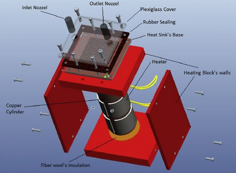
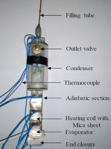
The scientists explored the heat-pulsed alumina/H2O nanofluid field in a 3D duct, and their findings revealed that increasing the size percentage of Al2O3 particle lowers the fluid temperature, however, using the nanofluid produces a pressure reduction in the channel [13, 14]. Valuable studies received by Jajja et al. [15] and Manova et al. [16] in different situations as shown in Figure 1.
(a) Heating block assembly [15]
(b) Ultra-thin multi-port minichannel thermosyphon [16]
Figure 1. Cooling of electronic devices
Menni et al. [17, 18] suggest that putting a channel with baffles in various situations into the flow can increase the efficiency of heat transmission inside the channel by using various designs of vortex generators. Menni et al. [19] also ran a number of flow models. In numerical experiments using porous fins, Hoseinzadeh et al. [20] employed the homotopy perturbation technique and the homotopy analysis technique to validate the solutions and compared them to the Runge-Kutta method. Hoseinzadeh et al. [21] verified the effect of storage engineering parameters such as PCM plate thickness and length, as well as the effect of air flow rate on storage outlet air temperature, in a numerical study of rectangular thermoelectric storage units with multiple phase-changing materials published in 2018.
Although, as stated at the outset of this introduction, air cooling has become insufficient to suit the demands of complicated electronic components. However, in recent years, it has been found in most laptops and other electronic devices. In this investigation, four commercial thermal heatsinks are used with various sorts that were cooled by air.
Various numerical and experimental experiments of these models were conducted in this manuscript to demonstrate the relevance of determining their shapes. The goal of each generation’s adjustments allowed us to derive new ideas for creating and enhancing computer and electronic device cooling. The effects of heatsinks height on thermal resistance are taken into account in order to discover ideal heatsink shapes that provide both high exchange heat transfer and lightweights. It began with experimental experiments, followed by numerical simulation study using Solid Works software.
The objective of the experiment is to assess the effectiveness of several commercial heatsinks as well as investigate the influence of their heights on their efficiency.
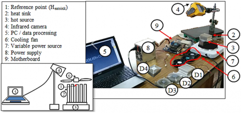
Figure 2 shows a schematic of the test bench that was used to represent the heatsink. The objective of these experiments was to find the best configuration that would give us the lowest temperature in the reference point in each trial under the identical conditions as the numerical research. The heat sink (2) was varied according to the experiment mode, and the hot source (3) was supplied by a variable power source (7).
Figure 2. Test bench
Thermal measurements were taken using a FLUK Ti10 thermal camera (4) [22], which allows scientists to see and record temperature readings (heatsink temperature) in point form (1). A thermal paste is used to connect the heatsink to the hot source (Figure 3). The fans (6) are driven by a motherboard (9) to guarantee that the microcomputer rotate at the correct speed and, the motherboard (9) receives electricity from the power supply (8).
Figure 3. Heatsink bonding to hot source
In this part, we will simply discuss the temperatures graph to compare the different types of heatsinks, and we will produce graphs of these experimental and numerical findings in the following numerical research to complete the talks and make the required comparisons.
The heatsinks (D1, D2, D3 and D4) were placed on top of the hot source each time, and we cooled the whole with different fans, the power source variable was regulated, the camera was directed towards the point (Tsource), then we waited a few minutes until the temperature value was stable (Tsource=350 K), and then we changed the camera’s direction to the reference point (px).
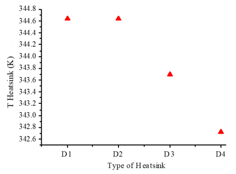
Figure 4. Variation of the temperature vs. the types of heatsinks
After collecting these temperatures for each model, it is possible to conclude that the heatsink D4 (heatsink with mixed geometry) is the best, since it has the lowest temperature measured in point px (Tpx=342 K) when compared to the other heatsinks (Figure 4).
In their experimental study, Ajaja et al. [15] looked at the influence of the spacing between the fins and the volume flow fluctuation on heat exchange and thermal performance, and discovered that reducing the distance between the fins enhances the transfer heat. This primarily what prompted us to consider the impacts of heatsink height on heat exchanger. As a result, a heatsink height of 28 mm was chosen as the start height, and the temperature at point py was calculated.
Figure 5. Heatsink D4 with reduced length
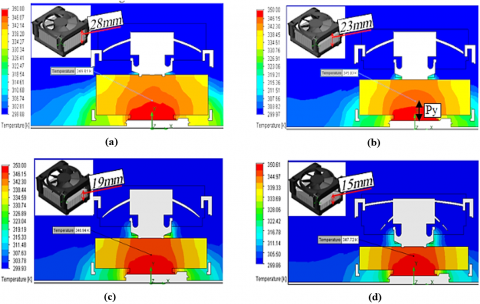
In this experiment, the length was shortened each time until the lengths of 23, 19 and 15 mm were attained, and the temperature was recorded in the same spots each time while preserving the same boundary conditions (to make this change in height, we cut it each time using a separator) (Figure 5). It is clear that the heights value and the minimum temperature are proportional. For large heights, the heatsink temperature is minimal (Figure 6). Thus, the length of the heatsink heights has significant impact on its efficiency. The height E1=28 mm is the best because it gives us the lowest temperature (Theatsink=345.81 K).
Figure 6. Variation of the temperature on the heat sink vs. heights
The experimental investigation is followed up with a numerical simulation using identical archetypes as in Table 1 to validate our models. The heat source was taken as a surface temperature of 350 K.
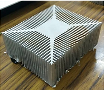
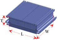
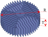
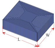
Table 1. Different types of heatsinks [D1: simple; D2: round (large size); D3: round (small size); D4: mixed]
|
Model |
Drawing with DAO |
Specifications |
|
D1 |
Weight: P=2.39 N Number of fins: N=28 Length: L=80 mm Width: W=80 mm Thickness: T=28 mm |
|
|
D2 |
Weight: P=1.72 N Number of fins: N=60 Diameter: R=95 mm Thickness: T=25 mm |
|
|
D3 |
Weight: P=0.98 N Number of fins: N=44 Diameter: R=84 mm Thickness: T=25 mm |
|
|
D4 |
Weight: P=3.12 N Number of fins: N=112 Length: L=82 mm Width: W=68 mm Thickness: T=28 mm |
Each model is put in a unique setting. The boundary conditions are discussed in details in Table 2.
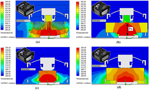
Because such points were generated in the experimental investigation, the findings were obtained as contours of temperatures for each model, with the temperature estimated in precise places px and py.
Table 2. Boundary conditions
|
Heatsink material |
Aluminium (ρ=2688.9 Kg/m3) |
|
Fluid |
Air |
|
Ambient temperature |
Tinlet=300 K |
|
Fan speed |
4400 RPM |
|
Heat source |
Surface temperature Tsource=350K |
4.1 Temperature contours of different heat sinks
Table 3 reports the different types of heat sinks with various experimental conditions.
Figure 7 shows that the heatsink D4 is the best situation (heatsink with mixed geometry) since its red zone (T=350) is modest compared to the others.
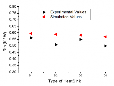
The graph in Figure 8 shows how numerical and experimental data are compared. If the value Rth for a certain heatsink is the smallest, it may be assumed that this situation provides adequate cooling, and hence this configuration is the best.
Table 3. Experimental conditions and different types of heatsinks
|
Heatsink |
D1 |
D2 |
D3 |
D4 |
|
heatsink Weight (N) |
2.39 |
1.72 |
0.98 |
3.12 |
|
T Source |
350 |
350 |
350 |
350 |
|
Rth (experimental) |
0.562 |
0.509 |
0.548 |
0.500 |
|
Rth (simulation) |
0.595 |
0.590 |
0.582 |
0.569 |
Figure 7. Temperature fields in different heat sinks: (a) D1, (b) D2, (c) D3, (d) D4
Figure 8. Variation in thermal resistance as a function of heatsink type
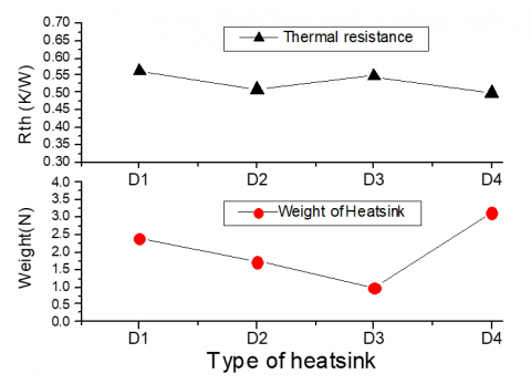
Figure 9. Comparison of thermal resistances and weights of heat sink
Figure 10. Temperature contours of different heights: (a) E1=28 mm, (b) E2=23 mm, (c) E3=19 mm, (d) E4=15 mm
The graph in Figure 9 compares the thermal resistances and weights for each heatsink to help you decide which is the best model. It is obvious that the heat sink D4 achieves good heat transfer because the thermal resistance is low (RTH=0.50 W/K), but this heatsink is very heavy compared to the others (P=3.12 N). Thus, the heatsink D3 is the best heatsink because it is very light (P=0.98 N), with a 59% improvement of 59%, and has a low thermal resistance with only a 9% loss.
4.2 Model D4 with different heights (E)
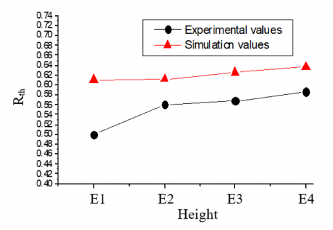
The heights of the most heatsink D4 are modified in this section to investigate their impacts on thermal resistance. The temperature contours are shown in Table 4 and Figure 10. A comparison between the numerical and experimental data are also conducted as reported in Figure 11.
Table 4. Different thicknesses of the D4 heatsink
|
Length E (mm) |
E1=28 |
E2=23 |
E3=19 |
E4=15 |
|
Heatsink Weight (N) |
3.12 |
2.56 |
2.115 |
1.67 |
|
Tsource |
350 |
350 |
350 |
350 |
|
Tpy (exp.) |
337.5 |
342 |
342.6 |
344 |
|
Tpy (numerical) |
345.81 |
345.93 |
346.94 |
347.72 |
It is worth noting that the two outcomes, simulation and experimental, have a comparable sensation, but there is also a significant discrepancy between the two outcomes owing to a lack of experience accuracy.
The plot in Figure 11 gives a comparison between the thermal resistances and the weights for each heatsink thickness. It is clear that the heatsink with E1=28 mm realizes a good heat transfer because it gives a low of thermal resistance (Rth=0.61 K/W) but it remains heavier than the others (P=3.12 N), therefore, we select the heatsink with length E3=19 mm which is with a weight of (P=2.11 N) and gives us a thermal resistance (Rth=0.62 K/W) as optimal heatsink.
Figure 11. Thermal resistances variation as a function of thickness heatsink type
This article looks at an experimental study followed by a numerical analysis.
The heatsinks are placed under the same conditions in the experimental study (ambient temperature, Tambient=300 K and hot source, Tsource=350K) to compare them (Simple D1, Round with large size D2, Round with small size D3, and mixed D4) taking into account good heat transfer and light weight.
The best heatsink was the D4 heat sink because its basic temperature is the lowest (Theatsink=342.7 K), but due to its heavy weight (P=3.12 N), the heatsink D3 was chosen as the optimal heatsink because it is very light (weight of 0.98 N) and gives a low temperature (Theatsink=343.69 K) similar to the previous D4.
Then, in the second phase, to validate the influence of heatsink height on efficiency, the same settings were maintained at the previous study limit of the D4 and its height was reduced each time, resulting in new heatsinks of the same type with varied heights.
To determine the ideal height, a comparison is made. This is the height that provides a low base temperature and light weights, of course. The best heat sink with 19 mm height gave us a Theatsink=345.7 K, with a weight of P=2.11 N.
[1] Mahajan, R., Nair, R., Wakharkar, V., Swan, J., Tang, J., Vandentop, G. (2002). Emerging directions for packaging technologies. Intel Technology Journal, 6(2): 62-75.
[2] Tuckerman, D.B., Pease, R.F.W. (1981). High-performance heat sinking for VLSI. IEEE Electron Device Letters, 2(5): 126-129. https://doi.org/10.1109/EDL.1981.25367
[3] Zhang, R., Hodes, M., Lower, N., Wilcoxon, R. (2013). Thermo-fluid characteristics of a minichannel heat sink cooled with liquid metal. In 29th IEEE Semiconductor Thermal Measurement and Management Symposium, pp. 159-165. https://doi.org/10.1109/SEMI-THERM.2013.6526822
[4] Rosa, P., Karayiannis, T.G., Collins, M.W. (2009). Single-phase heat transfer in microchannels: The importance of scaling effects. Applied Thermal Engineering, 29(17-18): 3447-3468. https://doi.org/10.1016/j.applthermaleng.2009.05.015
[5] Wei, X., Joshi, Y. (2004). Stacked microchannel heat sinks for liquid cooling of microelectronic components. J. Electron. Packag., 126(1): 60-66. https://doi.org/10.1115/1.1647124
[6] Zhang, H., Chen, L., Liu, Y., Li, Y. (2013). Experimental study on heat transfer performance of lotus-type porous copper heat sink. International Journal of Heat and Mass Transfer, 56(1-2): 172-180. https://doi.org/10.1016/j.ijheatmasstransfer.2012.08.047
[7] Capozzoli, A., Primiceri, G. (2015). Cooling systems in data centers: State of art and emerging technologies. Energy Procedia, 83: 484-493. https://doi.org/10.1016/j.egypro.2015.12.168
[8] Khoshvaght-Aliabadi, M., Sahamiyan M., Hesampour, M., Sartipzadeh, O. (2016). Experimental study on cooling performance of sinusoidal-wavy minichannel heat sink. Applied Thermal Engineering, 92: 50-61. https://doi.org/10.1016/j.applthermaleng.2015.09.15
[9] Naphon, P., Nakharintr, L. (2015). Numerical investigation of laminar heat transfer of nanofluid-cooled mini-rectangular fin heat sinks. Journal of Engineering Physics and Thermophysics, 88(3): 666-675. https://doi.org/10.1007/s10891-015-1235-1
[10] Safikhani, H., Dolatabadi, H. (2016). Multi-objective optimization of cooling of a stack of vertical minichannels and conventional channels subjected to natural convection. Applied Thermal Engineering, 96: 144-150. https://doi.org/10.1016/j.applthermaleng.2015.11.094
[11] Dean, R.N., Harris, D.K., Palkar, A.Y., Wonacott, G.D. (2012). Liquid metal-filled micro heat pipes for thermal management of solid-state devices. IEEE Transactions on Industrial Electronics, 59(12): 4888-4894. https://doi.org/10.1109/TIE.2012.2196893
[12] Medjahed, D.M., Ameur, H., Ariss, A, Medjadji, N., Mahammedi, A. (2016). Heat transfer improvement in micro-channel heat sinks by modifying some design and operating conditions. International Review of Mechanical Engineering (I.RE.M.E.), 10(6): 395-404.
[13] Hoseinzadeh, S., Otaghsara, S.T., Khatir, M.Z., Heyns, P.S. (2019). Numerical investigation of thermal pulsating alumina/water nanofluid flow over three different cross-sectional channel. International Journal of Numerical Methods for Heat & Fluid Flow, 30(7): 3721-3735. https://doi.org/10.1108/HFF-09-2019-0671
[14] Hoseinzadeh, S., Heyns, P.S., Kariman, H. (2019). Numerical investigation of heat transfer of laminar and turbulent pulsating Al2O3/water nanofluid flow. International Journal of Numerical Methods for Heat & Fluid Flow, 30(3): 1149-1166. https://doi.org/10.1108/HFF-06-2019-0485
[15] Jajja, S.A., Ali, W., Ali, H.M., Ali, A.M. (2014). Water cooled minichannel heat sinks for microprocessor cooling: Effect of fin spacing. Applied Thermal Engineering, 64(2): 76-82. https://doi.org/10.1016/j.applthermaleng.2013.12.007
[16] Manova, S., Godson Asirvatham, L., Nimmagadda, R., Raja Bose, J., Wongwises, S. (2019). Cooling of high heat flux electronic devices using ultra-thin multiport minichannel thermosyphon. Applied Thermal Engineering (2019). https://doi.org/10.1016/j.applthermaleng.2019.114669
[17] Menni, Y., Azzi, A. (2018). Numerical analysis of thermal and aerodynamic fields in a channel with cascaded baffles. Periodica Polytechnica Mechanical Engineering, 62(1): 16-25. https://doi.org/10.3311/PPme.10613
[18] Menni, Y., Azzi, A., Zidani, C., Benyoucef, B. (2016). Numerical analysis of turbulent forced-convection flow in a channel with staggered l-shaped baffles. Journal of New Technology and Materials, 6(2): 44-55. https://doi.org/10.12816/0043933
[19] Menni, Y., Azzi, A., Zidani, C. (2017). Use of waisted triangular-shaped baffles to enhance heat transfer in a constant temperature-surfaced rectangular channel. Journal of Engineering Science and Technology, 12(12): 3251-3273.
[20] Hoseinzadeh, S., Heyns, P.S., Chamkha, A.J., Shirkhani, A. (2019). Thermal analysis of porous fins enclosure with the comparison of analytical and numerical methods. Journal of Thermal Analysis and Calorimetry, 138(1): 727-735. https://doi.org/10.1007/s10973-019-08203-x
[21] Hoseinzadeh, S., Ghasemiasl, R., Havaei, D., Chamkha, A.J. (2018). Numerical investigation of rectangular thermal energy storage units with multiple phase change materials. Journal of Molecular Liquids, 271: 655-660. https://doi.org/10.1016/j.molliq.2018.08.128