Ahmed Allali* | Sadia Belbachir | Abdelkader Lousdad
© 2024 The authors. This article is published by IIETA and is licensed under the CC BY 4.0 license (http://creativecommons.org/licenses/by/4.0/).
OPEN ACCESS
Ventilation, carried out using centrifugal fans, is essential for obtaining good quality ambient air. Its role is to satisfy hygiene and comfort needs. It aims in particular to provide fresh air, in order to allow the proper functioning of the various devices, to evacuate air polluted by various pollutants and to combat humidity and condensation. In this context, the objective of this work is to study the internal flow of humid air for different concentrations in a fan rotor using the ANSYS-CFX software, based on the finite volume method. Flow turbulence is taken into account using the k-Ɛ model. The scientific contribution in this field consists of showing that the concentration of humid air has a considerable effect on the properties of the flow such as: pressure, shear stresses and flow speed which is in agreement with the results of experimental studies. This study can be used to locate the area’s most exposed to this change in flow properties and which will result in premature damage to the blades by erosion and a reduction in fan efficiency. It will therefore be possible to take preventive measures to minimize the harmful effects of humidity concentration on centrifugal fans.
fan, impeller, dry air, humid air, turbulent flow
Centrifugal fans are receiver turbo machines comprising one or more wheels around an axis, driven by mechanical power transmitted to it. Their design consists of one or more impellers with rotating vanes, suction and injection mechanisms. The air is sucked in parallel to the axis of rotation and propelled by centrifugal force perpendicular to this same axis. They are widely used, notably in air conditioning systems used in the aeronautical industry, the automobile industry and in many other applications. Centrifugal fans used to exhaust hot humid air will be the subject of this work. It is in this context that we propose to study the flow of humid air in the rotor of a fan. We seek to see the influence of the concentration of humid air on the properties of the flow. Several of our works that have been carried out have touched the field of turbo machinery [1]. Scientific research on fans includes numerical and experimental studies of the aerodynamics of a centrifugal fan with backward-facing blades [2]. Work on improving fan system performance [3] and the basics of flow in an axial fan [4]. Characterization of the flow in mining ventilation fan blades [5]. Simulation and analysis of an axial fan for sending heat into the tube tunnel furnace, and find the relationship between the total pressure and the total pressure efficiency of the fan at different blade angles and different operating conditions. Inlet air flow [6]. The performance optimization study of a blade axial fan was analyzed in 3D [7]. Numerical and experimental analysis of the influence of the blade perforation on the internal flow field [8]. A study of air distribution by fan coil and displacement systems as well as the prediction and reduction of aerodynamic noise of the multi-blade centrifugal fan was carried out respectively [9, 10]. More other work concerning cross flow fans [11-16]. In our case we focused on the study of the influence of the concentration of humid air on the properties of the flow circulating through the blades of a fan. A comparison between dry air and humid air is proposed. We focused on the study of the impact of concentration of air humidity on the blades of a centrifugal fan impeller which can cause premature wear of the blades and reduce the lifespan of the fan. Most of the research proposed in this area focuses much more on the study of ventilation than on the study of fans.
The geometry is reconstructed from the geometric information of the fan wheel and its characteristics which are summarized in Table 1 and Table 2. The creation of the geometry is done by software called ICEM. It allows you to create 3D geometry according to the model, directly to real scale from objects such as points, lines, surfaces and volumes.
Table 1. Characteristics of the ventilator
|
Mass Flow Q [kg/s] |
Rotation Speed N [trs/min] |
|
0.15 |
4500 |
Table 2. Geometric dimensions of the impeller of the ventilator
|
Dimensions |
Value |
|
Average diameter at blade entry: d1 [mm] |
92 |
|
Width at blade entry: b1 [mm] |
42 |
|
blade entry angle β1 [°] |
24 |
|
Average diameter at blade exit: d2 [mm] |
180 |
|
Width at blade exit: b2 [mm] |
30 |
|
blade exit angle: β2 [°] |
24 |
|
Number of blades: z |
10 |
|
Blade thickness: e [mm] |
1 |
Humid air is a mixture of gases containing water vapor. The thermodynamic properties of this mixture are strongly influenced by the presence of water vapor, which can also condense under certain temperature and pressure conditions. Knowledge of a descriptive parameter of humidity is necessary to characterize the thermodynamic state of humid air Table 3.
Table 3. Thermodynamic properties of the air
|
Concentration of Humid Air |
Dry Air |
Humid Air 20% |
Humid Air 40% |
Humid Air 60% |
|
Specific heat capacity Cp [KJ.kg-1.K-1] |
1.01 |
1.205 |
1.405 |
1.610 |
|
Density [kg.m-3] |
0.93 |
0.87 |
0.80 |
0.73 |
|
Thermal conductivity l0 -3 [W.m-1.K-1] |
31.3 |
32.01 |
32 |
30.8 |
|
Dynamic viscosity l0-6 [kg.m-1.s-1] |
21.9 |
20.9 |
19.4 |
17.3 |
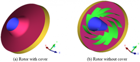
The configuration of the rotor under study is with and without cover of a ventilator represented in Figure 1. The wall of the rotor is assumed to be not deformable and unfavorable to sliding. The simulation was carried out using a rotor with its cover. But for greater clarity of the simulation results, the cover was removed so that we could see the inside of the rotor.
Figure 1. Configuration of the rotor
The geometrical complexity generated by the aerodynamic forms of the different components constituent of the turbo-machines make the numerical modeling of the flows very difficult.
However, the appearance of the new meshing techniques has allowed simplifying the problem and obtaining excellent results. Meshing is an important phase in the simulation of turbo-machines due to its effect on the solution.
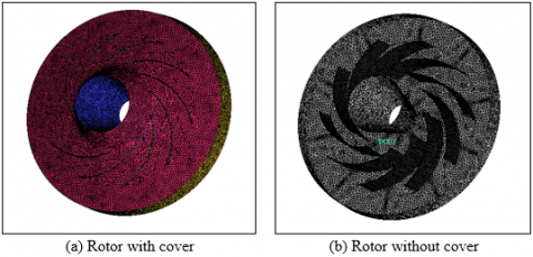
The meshing was made using the computational software code ANSYS ICEM. The mesh is of structured tetrahedral type as shown in Figure 2.
The tetras are very flexible elements which make it possible to faithfully reconstruct the complex geometry of the passages in the fan with sufficient refinement. The counterpart of the use of tetras is the emergence of a large number of variables to be stored, which quickly makes the dimension of the problem to be solved quite large and difficult to handle. The generation of the mesh in each fluid domain is highly automated through an adequate distribution of the areas to be meshed and a good adjustment of the parameters.
Figure 2. Meshing of the rotor
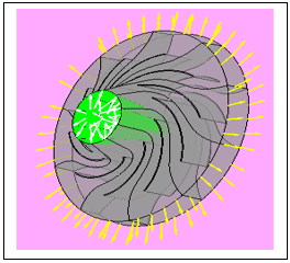
The domain of the computation is defined by CFX-Pre module of the computational code ANSYS-CFX. The internal flow is assumed to be tridimensional, turbulent (k-Ɛ model) of a compressible fluid at a temperature of 100℃ with inlet pressure of 101325 Pa and an outlet mass flow rate equal to 0.15 kg/s. The calculation of the parameters is based on Nervier Stocks’ equations and energy equation. The interface chosen is of Rotational periodicity type. The rotational speed is 4500 trs/min. The loading has been modulated as shown in Figure 3.
Figure 3. Boundary conditions
The results concerning the pressure, the shear rate, the shear stresses and the speed are grouped in order to obtain a comparison for each humid air concentration. The evolutions of these parameters are illustrated in figures from Figure 4 to Figure 10.
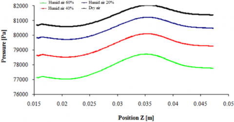
7.1 Evolution of the pressure
From Figures 4 and 5 it can be noticed that the complex form of the rotor creates a geometric dissymmetry which is deprecated on the pressure field. The fluid penetrates axially and is subjected to a sudden change of the trajectory under the effect of the centrifugal forces generated by the rotation of the wheel. This change of direction of the fluid particles causes a partial feed of the blades of the wheel leading to considerable loss of pressure.
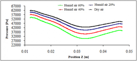
Figure 4. Evolution of the pressure at the intrados with respect to position (Z)
From the obtained pressure plots along the Z-axis it is observed that there exists a significant gap between the four types of fluids. The pressure is decreased at the intrados with respect to the blade extrados. More the concentration of humid air is increased the more the pressure decreases. We notice from the pressure plots at the intrados that their values are higher at the inlet and continuously decreasing up point Z=0.035 where the value of the pressure is minimum. After this point, the values of the pressure increase continuously. While, for the pressure plots at the extrados in the inlet region of the blades, the values of the pressure are lower with respect to the outlet region and at point Z=0.035 the pressure reaches its maximum value. This reduction in pressure in the fan suction zone is observed where the air is sucked in by the blades. The pressure increases in the compression zone of the air flow or the fan blades accelerate the air. A region of low pressure is observed downstream of the fan, resulting from the formation of the recirculation zone.
Figure 5. Evolution of the pressure at the intrados with respect to position (Z)
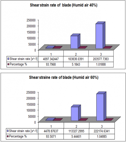
7.2 Profile of the speed of deformation
The action of a flow on a wall is characterized by the shear stress at the wall. It expresses the friction force acting tangentially on the wall, per unit area. From the four histograms for different gas types, we notice that the shear rate distribution is not uniform with very different proportions in the blade.
The strain rate values oscillate strongly with a percentage of 0.9% of the blade. The fan blade shear rate increases with increasing moist air concentration Figure 6.
Figure 6. Percentage speed of deformation in the blade
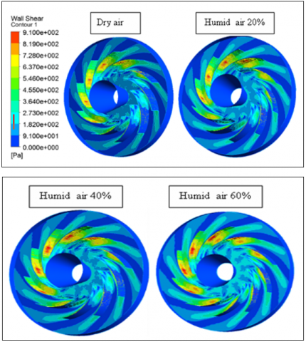
7.3 Shear stress
According to the stress distribution contours given in Figure 7, the shear stresses are not uniformly distributed and we notice that in the blade inlet region the shear stress is greater than that of the remaining part of the fan rotor.
Figure 7. Shear stress contours
The shear stress in the fan rotor increases with increasing humid air concentration. From the Newtonian fluid formula, we deduce that as the fluid viscosity increases and consequently the speed gradient decreases, the shear stress decreases.
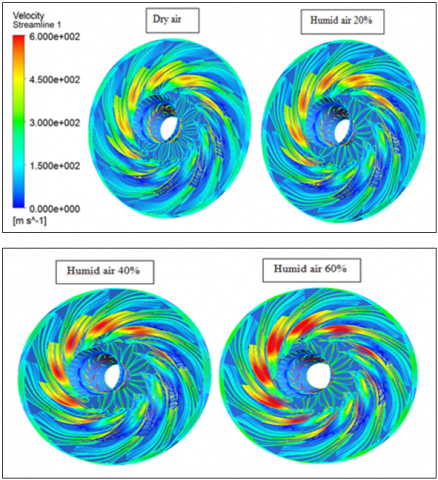
7.4 Streamlines
The representation of the streamlines in Figure 8 allows us to see the structure of the flow in the rotor.
Figure 8. The streamlines in the rotor
The areas of the blades near the rotor inlet are denser in the case of more concentrated humid air. On the other hand, the organization of the streamlines is almost similar for the four types of fluids studied. Dry air is more resistant than humid air to the formation of recirculation zones generated by the presence of bends in the rotor. This recirculation zone is observed downstream of the fan, creating a region of low speed and local stagnation. Maximum speeds are reached near the fan blades, indicating an acceleration of the airflow as it is propelled by the blades. The higher the viscosity rate in the fluid, the less important these zones are. This shows that the structure of the flow is sensitive to the nature of the fluid. This study can be beneficial for targeting specific areas that require more intense ventilation.
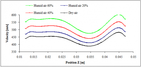
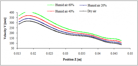
7.5 Evolution of the velocities
Figures 9 and 10 represent the flow velocity modulus. They show an increase in speed with increasing concentration of humid air. The velocity module decrease due to the geometry of the rotor blade wall which represents a curvature and also the boundary layer which represents the thin fluid layer which is influenced by contact with the wall. Variations in blade profile shape, curvature, and thickness result in differences in the velocity fields, with regions of higher or lower velocity depending on the fan blade profile. The values of the speed curves at the level of the intrados, the exit speed is slightly higher than the entry speed and the minimum speed is at the point Z=0.035. As for the speed values at the level of the extrados, the curves are decreasing from the input region to the end of the output region, that is to say that the higher the value of Z, the lower the value of the speed.
Figure 9. Evolution of the velocity module with respect to position (Z) at the intrados
Figure 10. Evolution of the velocity module with respect to position (Z) at the extrados
To conclude, this work allowed us to see how the different properties of air flow in the rotor of a fan are influenced by the humidity level in the air. It was found that for high concentration of humid air, the pressure values are less compared to those of dry air in both intrados and extrados positions of the fan blade. The pressure values are large at the extrados compared to the intrados. On the other hand, the flow velocity modules evolve in an inverse manner compared to the pressure evolution. The shear stress in the fan rotor increases with increasing humid air concentration. In the inlet region of the blade the shear stress is greater than that of the remaining part of fan rotor. Dry air is more resistant than humid air to the formation of recirculation zones generated by the presence of bends in the rotor. The nature of the fluid has a considerable effect on the structure of the flow. These results may have an impact on the efficiency and performance of the fan. They represent a contribution to suggest the best solution to maximize energy efficiency and prevent damage to fans operating in humid environments.
[1] Allali, A., Belbachir, S., Alami, A., Boucham, B., Lousdad, A. (2020). The effect of the outlet angle on the thermomechanical behavior of a centrifugal compressor blade. Journal of the Mechanical Behavior of Materials, 29(1): 1-8. https://doi.org/10.1515/jmbm-2020-0001
[2] Zhang, J.H., Chu, W.L., Zhang, H.G., Wu, Y.H., Dong, X.J. (2016). Numerical and experimental investigations of the unsteady aerodynamics and aero-acoustics characteristics of a backward curved blade centrifugal fan. Applied Acoustics, 110: 256-267. https://doi.org/10.1016/j.apacoust.2016.03.012
[3] Berkeley, L. (2003). Improving Fan System Performance a Sourcebook for Industry U.S. Department of Energy Energy Efficiency and Renewable Energy, Washington, D.C. 20585 DOE/GO-102003-1294. https://www.nrel.gov/docs/fy03osti/29166.pdf.
[4] Hudson Products Corporation. A McDermott company. The Basics of Axial Flow Fans 2000. pp: 1-35. https://www.eurovent.eu/sites/default/files/field/file/PP%20-%202015-05-23%20-%20Attachment%20-%20 Hudson%20tip%20clearance%20example%20-%20page%2015%20-%20figure%206.pdf.
[5] Hassen, A.E. (2021). Flow characterization in mine ventilation fan blade design using CFD. Journal of Sustainable Mining, 20(3): 2. https://doi.org/10.46873/2300-3960.1063
[6] Yang, T.C., Chen, X.L., Cheng, H.M. (2015). Aerodynamic performance analysis of axial-fan in low pressure pipeline based on ANSYS CFX. In Proceedings of the 2015 Joint International Mechanical, Electronic and Information Technology Conference. https://doi.org/10.2991/jimet-15.2015.65
[7] Koten, A.P.D.H. (2018). CFD modeling and multi-objective optimization of the axial fan parameters. Journal of Energy Systems, 2(4): 137-144. https://doi.org/10.30521/jes.454146
[8] Yang, X.L., Wu, C.H., Wen, H.B., Zhang, L.L. (2017). Numerical simulation and experimental research on the aerodynamic performance of large marine axial flow fan with a perforated blade. Journal of Low Frequency Noise, Vibration and Active Control, 37(3): 410-421. https://doi.org/10.1177/0263092317714697
[9] Cammarata, G., Galluccio, M., Vinci, D., Raciti, L. (2016). Air distribution through fan coil and displacement systems. International Journal of Heat and Technology, 34(2): S249-S254. https://doi.org/10.18280/ijht.34S209
[10] Zhou, S.Q., Wang, J. (2014). Prediction and reduction of aerodynamic noise of the multiblade centrifugal fan. Hindawi Publishing Corporation, Advances in Mechanical Engineering, 2014: 712421. https://doi.org/10.1155/2014/712421
[11] Toffolo, A., Lazzaretto, A., A. Martegani, D. (2004). Cross-flow fan design guidelines for multi-objective performance optimization. Proceedings of the Institution of Mechanical Engineers, Part A: Journal of Power and Energy, 218: 33-42. https://doi.org/10.1243/095765004322847071
[12] Chen, A., Li, S., Huang., D. (2008). Numerical analysis of aerodynamic noise radiated from cross flow fan front. Frontiers of Energy and Power Engineering in China, 2: 443-447. https://doi.org/10.1007/s11708-008-0063-9
[13] Toffolo, A. (2005). On the theoretical link between design parameters and performance in cross-flow fans: A numerical and experimental study. Computers & Fluids, 34(1): 49-66. https://doi.org/10.1016/j.compfluid.2004.04.002
[14] Shih, Y.C., Hou, H.C., Chiang, H. (2008). On similitude of the cross flow fan in a split type air-conditioner. Applied Thermal Engineering, 28(14-15): 1853-1864. https://doi.org/10.1016/j.applthermaleng.2007.11.022
[15] Dang, T.Q., Bushnell, P.R. (2009). Aerodynamics of cross-flow fans and their application to aircraft propulsion and flow control. Progress in Aerospace Sciences, 45(1-3): 1-29. https://doi.org/10.1016/j.paerosci.2008.10.002
[16] Moon, Y.J., Cho, Y., Nam, HS. (2003). Computation of unsteady viscous flow and aero acoustic noise of cross flow fans. Computers & Fluids, 32(7): 995-1015. https://doi.org/10.1016/S0045-7930(02)00068-3