Yuan Wang![]()
© 2024 The authors. This article is published by IIETA and is licensed under the CC BY 4.0 license (http://creativecommons.org/licenses/by/4.0/).
OPEN ACCESS
In the context of the global energy crisis and environmental shifts, solar energy, recognized for its cleanliness and renewability, has increasingly captured attention in the application within the architectural sector. As a significant portion of energy consumption, the electrification of buildings and their transformation towards green systems are crucial for energy saving and emission reduction. With technological advancements, solar-powered building electrical systems have emerged as a focal point of research. The core issues affecting their widespread application are the system's thermodynamic efficiency and integration strategies. Despite advancements in solar cell efficiency and device-level optimization, there remains a deficiency in system-level thermodynamic analysis and integrated optimization, limiting the efficiency and practicality of solar energy in construction. This study initiates with an energy and exergy analysis to delve into the thermodynamic efficiency of solar-powered building electrical systems, clarifying the efficiency of energy conversion and the irreversibility losses. Building on these findings, strategies for system integration and operational optimization are proposed, aiming for a comprehensive optimization of solar systems through the establishment of targeted design and operational standards. This research not only provides a theoretical foundation for enhancing the energy efficiency of solar systems but also offers practical guidance for designing and managing efficient, sustainable building electrical systems.
solar energy, building electrical systems, thermodynamic efficiency, energy analysis, exergy analysis, system integration, operational optimization
With the continuous increase in global energy consumption and the exacerbation of environmental issues, the development and utilization of renewable energy have become urgent issues to be addressed worldwide [1-3]. Among renewable energy technologies, solar energy has become a focal point of research due to its cleanliness, inexhaustibility, and wide distribution [4, 5]. Particularly in the field of architecture, the utilization of solar energy can not only reduce the operational energy consumption of buildings but also help decrease greenhouse gas emissions, which is of significant importance for achieving green buildings and sustainable development [6, 7]. As one of the key technologies to achieve this goal, the study of the thermodynamic efficiency and integration strategies of solar-powered building electrical systems is particularly important.
The application of solar energy technology in buildings is not only related to energy saving but also a key factor in improving the quality of the building environment and promoting economic sustainable development [8-10]. Effective solar energy integration strategies can ensure that buildings are self-sufficient in energy under different environmental and climatic conditions, while optimizing energy consumption patterns and improving energy efficiency [11, 12]. Therefore, conducting in-depth analyses of the thermodynamic efficiency and integration strategies of solar-powered building electrical systems is of great theoretical and practical significance for promoting the application of solar energy technology in buildings.
However, existing research mostly focuses on the singular performance evaluation of solar energy systems or device-level optimizations, with less attention given to systemic thermodynamic efficiency analyses and comprehensive integration optimization strategies [13-17]. This has led to suboptimal performance of solar energy systems in practical applications, where system integration often lacks targeted design and operational optimization standards, failing to fully realize the potential environmental and economic benefits of solar energy [18-20].
This paper first conducts a detailed analysis of the thermodynamic efficiency of solar-powered building electrical systems, using energy and exergy analysis methods to systematically assess the energy losses and irreversibilities in the solar conversion process, revealing the key factors affecting system efficiency. Secondly, the paper proposes a set of integration and operational optimization schemes for solar-powered building electrical systems, starting from integrated design to clarify optimization objectives and establish a comprehensive evaluation standard. This research not only provides guidance for optimizing the thermodynamic performance of solar systems but also lays a theoretical and practical foundation for the efficient integration and operational management of building electrical systems, which is of significant research value for promoting the widespread application and energy efficiency improvement of solar technology in the field of architecture.
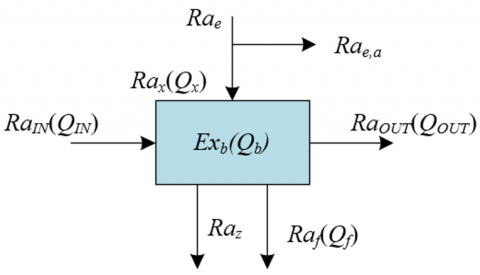
As the building industry's requirements for energy efficiency continue to increase, solar-powered building electrical systems have shown their immense potential and challenges. Therefore, it is crucial to conduct an in-depth analysis of the thermodynamic performance of these systems. This paper studies solar thermal systems through energy and exergy analysis, which can not only reveal the efficiency losses and irreversibilities in the energy conversion and utilization process but also identify and quantify various influencing factors, providing precise scientific basis for system design and optimization. Figure 1 shows the thermodynamic model of the solar thermal system.
Figure 1. Thermodynamic model of the solar thermal system
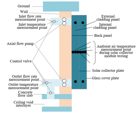
Figure 2. Temperature measurement points arrangement in the solar thermal system
2.1 Energy analysis
Energy analysis provides us with an effective tool for assessing energy conversion efficiency and system performance. Specifically, by conducting an energy analysis on the solar thermal system, this paper is able to quantitatively calculate the energy flow in the process of collecting, converting, and distributing solar energy, identify the main segments of energy loss, and assess the impact of different design parameters on system performance. Figure 2 presents the temperature measurement points arrangement of the solar thermal system.
Establishing the energy balance equation for the solar thermal system is a basic step in energy analysis. This equation considers all energy flows entering and leaving the system, including solar radiation energy, environmental heat losses, and the energy gained or lost through the working fluid. The following equation provides the energy balance equation for the constructed thermal system:
$W_x=W_y+W_f+\left(W_{O U T}-W_{I N}\right)$ (1)
Furthermore, the effective heat obtained by the solar thermal system is calculated. Effective heat refers to the thermal energy that the system actually converts and is available for use, reflecting the system's actual working capacity. This step calculates the effective energy gain by monitoring the solar irradiance at the system's input and the thermal energy flow at the output, thereby assessing the collection efficiency. This process takes into account the effects of actual operating conditions, such as weather changes, sunlight hours, etc. Assume the mass flow rate of water is represented by l, the specific heat capacity of water at constant pressure is represented by Zo, and the inlet and outlet temperatures of water in the thermal system are represented by Sd,IN and Sd,OUT, respectively. The following equation provides the formula for calculating the effective heat obtained by the solar thermal system:
$W_i=W_{\text {OUT }}-W_{I N}=l Z_o\left(S_{d, O U T}-S_{d, I N}\right)$ (2)
Assume the effective light-collecting area of the thermal system is represented by $X_o$. The total heat loss coefficient of the thermal system is represented by $I_m$, the heat dissipation coefficient of the thermal system is represented by $D_E$, the efficiency factor of the thermal system is represented by $D$, the light conversion rate is represented by $\lambda_0$, and the temperatures of the thermal system and the environment are represented by $S_c, S_x$. Considering these factors such as heat losses and light conversion efficiency, the calculation formulas are as follows:
$W_i=X_o\left[T-I_m\left(S_c-S_x\right)\right]$ (3)
$W_i=X_o D_E\left[T-I_m\left(s_{d, I N}-s_x\right)\right]$ (4)
$T=\lambda_0 U_S$ (5)
$D_E=\frac{l Z_o}{X_o I_m}\left[1-\exp \left(-\frac{D^{\prime} I_m X_o}{l Z_o}\right)\right]$ (6)
Finally, the system efficiency of the thermal system is calculated. This step involves comparing the effective heat with the total energy input (such as total solar radiation energy) to derive the efficiency value. System efficiency not only reflects the performance of the collector but also includes the efficiency of other system components, such as heat exchangers, storage systems, etc. This efficiency indicator is directly related to the economic and practical aspects of energy conversion, being a key parameter for optimizing system design and improving performance. The following equation provides the formula for calculating the system efficiency of the thermal system:
$\lambda_{s g}=\frac{W_i}{X_o U_S}$ (7)
Considering the temperature distribution in the thermal system, the following can be applied:
$\frac{S_{d, \text { OUT }}-S_x-\frac{T}{I_M}}{S_{d, I N}-S_x-\frac{T}{I_M}}=\exp \left(\frac{D^{\prime} I_M X_o}{l Z_o}\right)$ (8)
The efficiency of the solar thermal system under stable operation can also be calculated using the following equation:
$\begin{align}
& {{\lambda }_{sg}}=\frac{l{{Z}_{o}}\left[ \left( {{S}_{d,IN}}-{{S}_{x}}-\frac{T}{{{I}_{M}}} \right)\left( \text{exp}\left( -\frac{D'{{I}_{M}}{{X}_{o}}}{l{{Z}_{o}}} \right)-1 \right) \right]}{{{X}_{o}}{{U}_{S}}} \\
& =\frac{l{{Z}_{o}}\left[ \text{exp}\left( \frac{D'{{I}_{M}}{{X}_{o}}}{l{{Z}_{o}}} \right)\left( {{S}_{d,OUT}}-{{S}_{x}}-\frac{T}{{{I}_{M}}} \right)\text{exp}\left( -\frac{D'{{I}_{M}}{{X}_{o}}}{l{{Z}_{o}}} \right)-1) \right]}{{{X}_{o}}{{U}_{S}}} \\
\end{align}$ (9)
2.2 Exergy analysis
As an important means of measuring the irreversibility of systems, exergy analysis plays an irreplaceable role in enhancing the thermodynamic efficiency of solar thermal systems. Through exergy analysis, the irreversible processes present in the system, such as heat dissipation, fluid friction, and chemical reactions, can be qualitatively and quantitatively analyzed, thereby revealing the fundamental limitations of system efficiency.
Firstly, the exergy balance equation of the system is established. The exergy balance equation takes into account the exergy flows received and emitted by the system, including solar radiation, environmental heat transfer, and working fluid flow, among all factors that can cause changes in the system's exergy. To establish exergy balance, it is necessary to measure or calculate the energy and material enthalpy and exergy flows, ensuring that the sum of all input and output exergy flows is zero, or equals the generation of exergy within the system, thereby revealing the system's irreversibility. The exergy input to the solar thermal system includes the exergy of absorbed solar heat and the exergy of heat in the water entering the thermal system, represented by RAx and RAIN, respectively. The system's exergy output is the exergy of heat in the water exiting the thermal system, represented by RAOT. The system's exergy loss comprises the exergy of heat dissipated by the thermal system and the exergy loss caused by irreversible processes in the thermal system, represented by RAf and RAz, respectively. The following equation provides the expression for the system's exergy balance equation:
$\sum R_{A_x}+\sum R_{A_{I N}}-\sum R_{A O U T}=\sum R_{A_z}+\sum R_{A_f}$ (10)
The process of heat transfer is often accompanied by a temperature gradient, and the temperature gradient is the main cause of exergy generation. By calculating the heat exergy, it can be determined how much available energy is lost in the heat transfer process, thereby assessing the heat transfer efficiency. Assuming the heat transfer amount during the heat transfer process is represented by W, and the temperature of the heat transfer substance is represented by S, the following equation provides the calculation formula for the heat exergy of the heat transfer process when the environmental temperature is S0:
$R_{a_{H E}}=Q\left(1-\frac{S_0}{S}\right)$ (11)
The calculation of exergy involves the quality of solar radiation, i.e., its temperature level. Higher fire exergy means the thermodynamic quality of solar radiation is higher, and the system may utilize this part of the energy more efficiently. The calculation of fire exergy requires solar radiation power data, as well as the difference with the environmental temperature. These data can usually be obtained through weather stations or solar radiation monitoring equipment. Assuming the solar surface temperature is represented by St, the following equation provides the calculation formula for the solar radiation fire exergy RAe:
$R_{A_e}=U_S X_O\left(1-\frac{S_x}{S_t}\right)$ (12)
The mass flow, i.e., the working fluid flow, is the medium of energy transfer in the thermal system. The calculation of its exergy value needs to consider the state of the working fluid (such as temperature and pressure) and its flow characteristics in the system. By calculating the exergy of the mass flow, the energy utilization efficiency during the working fluid transportation process can be assessed, and how to improve the working fluid flow to reduce energy loss can be determined. The calculation formulas for the exergy of the working fluid water in the thermal system are as follows:
$R_{A d}=l Z_o\left[\left(S_d-S_x\right)-S_x \ln \left(\frac{S_d}{S_x}\right)\right]$ (13)
$R_{A N}=l Z_o\left[\left(S_{d, I N}-S_x\right)-S_x \ln \left(\frac{S_{I N}}{S_x}\right)\right]$ (14)
$R_{A_{\text {OUT }}}=l Z_o\left[\left(S_{d, O U T}-S_x\right)-S_x \ln \left(\frac{S_{d, O U T}}{S_x}\right)\right]$ (15)
When the working fluid in the system absorbs or releases heat, its state changes, and accordingly, its exergy increases. This increase in exergy represents the irreversible losses in the energy conversion process. To calculate the exergy increase caused by the state change of the working fluid, it is necessary to track the state changes of the working fluid in the collector, heat exchanger, and storage system. In the calculation process, the enthalpy and entropy changes of each state point need to be converted into exergy changes, to assess the irreversible losses in the energy conversion and transfer process. The following equation provides the calculation formula for the increase in exergy of the working fluid water in the thermal system:
$R_{A_{d, O U T}}-R_{A_{d, N V}}=l Z_o\left[\left(S_{d, O U T}-S_{d, I N}\right)-S_x \ln \left(\frac{S_{d, O U T}}{S_{d, I N}}\right)\right]$ (16)
Exergy efficiency considers the exergy balance of all components of the system and is an important indicator for evaluating the overall thermodynamic performance of the system. By comparing the total exergy input of the system and the exergy output of useful work, the system's exergy efficiency can be derived. The calculation formula for the exergy efficiency of the thermal system is:
${{\lambda }_{ra}}=\frac{l{{Z}_{o}}\left[ {{S}_{d,OUT}}-{{S}_{d,IN}} \right]-{{S}_{x}}\text{ln}\left( \frac{{{S}_{d,OUT}}}{{{S}_{d,IN}}} \right)}{{{X}_{o}}{{U}_{S}}\left[ 1-\left( \frac{{{S}_{x}}}{{{S}_{t}}} \right) \right]}=\frac{l{{Z}_{o}}\left\{ \begin{align}
& \left( {{S}_{d,OUT}}-{{S}_{d,IN}}-\frac{T}{{{I}_{M}}} \right)\left[ 1-\text{exp}\left( \frac{{{I}_{M}}{{X}_{o}}D'}{l{{Z}_{o}}} \right) \right]- \\
& {{T}_{a}}\ln \left( \frac{{{T}_{f,out}}}{\text{exp}\left( \frac{{{I}_{M}}{{X}_{o}}D'}{l{{Z}_{o}}} \right){{S}_{d,OUT}}+\left( {{S}_{x}}+\frac{T}{{{I}_{M}}} \right)\left[ 1-\text{exp}\left( \frac{{{I}_{M}}{{X}_{o}}D'}{l{{Z}_{o}}} \right) \right]} \right) \\
\end{align} \right\}}{{{X}_{o}}{{U}_{S}}\left[ 1-\left( \frac{{{S}_{x}}}{{{S}_{t}}} \right) \right]}$ (17)
Figure 3. Model architecture of a solar-powered building electrical system
As the global focus on sustainable development and green buildings continues to grow, solar-powered building electrical systems, as a solution utilizing renewable resources, have become particularly important in research and development. This paper focuses on enhancing the thermodynamic efficiency of solar systems in buildings and optimizing system integration strategies, which can provide scientific theoretical basis and practical technical support for the energy optimization management of building electrical systems. This, in turn, promotes the development of intelligent buildings and smart cities, with significant economic, environmental, and social benefits. Figure 3 presents the model architecture of a solar-powered building electrical system.
3.1 Optimization objective design
The optimization objective design of this paper is centered around the internal energy flow of the solar-powered building electrical system, conducting empirical research on a specific community through a refined simulation platform. Specifically, the research will first conduct a comprehensive assessment of the total energy demand of the target community, including peak and base load analysis. Based on this, further assessment and optimization of the configuration and size of system components are carried out to ensure maximization of thermodynamic efficiency. Then, considering the economy, an optimal balance between economic investment and energy output is found through cost-benefit analysis to reduce the total operational cost of the system. Meanwhile, the environmental impact is considered, specifically by calculating and optimizing CO2 emissions to achieve an environmentally friendly system design. The entire optimization process will employ a multi-objective optimization method, striving not only for maximum energy efficiency but also ensuring the system is sustainable in terms of economic and environmental benefits. Figure 4 provides the integration and operational optimization strategies of the solar-powered building electrical system.
Before the integration and operational optimization of the solar-powered building electrical system, thermodynamic models of the main components in the system were established, as follows:
To fully utilize solar energy and enhance the performance of the collection system, this paper first conducts thermodynamic modeling of the collection system. The model uses energy balance equations to describe the energy exchange between the inside and outside of the collector, including the absorption of incident solar energy, the thermal gain of the fluid inside the system, and heat loss due to the environment. By simulating heat acquisition under different weather conditions, the design parameters of the collector, such as its inclination, area, fluid type, and flow rate, can be optimized to maximize thermal energy collection. Assume the total heat collected by the system in the s-th hour is represented by Wz(s). The total area of the solar thermal system is represented by Xt. The total solar radiation in the s-th hour is represented by H(s). The collection efficiency of the system in the s-th hour is represented by λz(s). The temperature of the collection system in the s-th hour is represented by sIN(s). The external temperature of the storage tank in the s-th hour is represented by sx(s). The heat transfer coefficient is represented by Jz. Thus, the model of the collection system is:
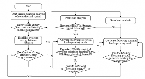
Figure 4. Integration and operational optimization strategies of the solar-powered building electrical system
The thermal storage tank is a key component of the solar system, used to store thermal energy to balance supply and demand. The thermodynamic model of the thermal storage tank is based on the thermodynamic principles of heat storage and release. The model uses the law of conservation of energy to describe the process of thermal energy storage, taking into account the thermal conduction of the storage medium, natural convection, and heat exchange with the external environment. Assume the total heat stored in the thermal storage tank in the s-th hour is represented by W2(s). The time difference is represented by ΔS. The rate of heat storage and release of the thermal storage tank in the s-th hour is represented by R2(g). The minimum amount of heat storage in the thermal storage tank is represented by (W2)MIJN. The external temperature of the thermal storage tank in the s-th hour is represented by sx(s), and the heat stored during the start to end time interval is represented by z. Thus, the model of the thermal storage tank is:
$\left\{ \begin{align}
& {{W}_{z}}\left( s \right)=0.001{{X}_{t}}\cdot H\left( s \right){{\lambda }_{z}}\left( s \right) \\
& {{W}_{z}}\left( f \right)=\sum\limits_{0}^{24}{{{W}_{z}}\left( s \right)} \\
& {{\lambda }_{z}}\left( s \right)={{x}_{0}}-{{x}_{1}}{{\left( {{s}_{IN}}\left( s \right)-{{s}_{x}}\left( s \right)/H\left( s \right)-{{x}_{2}}\left( {{s}_{IN}}\left( s \right)-{{s}_{x}}\left( s \right) \right) \right)}^{2}}/G(t) \\
& {{\lambda }_{z}}\left( s \right)\cdot {{e}_{z}}\left( s \right)\ge 0 \\
& {{e}_{z}}\left( s \right)\in \left\{ 0,1 \right\} \\
\end{align} \right.$ (18)
The ORC power generation system is a key link in converting thermal energy into electrical energy. This model analyzes and calculates the energy and entropy changes in the system through the first and second laws of thermodynamics, considering the irreversible losses in the actual cycle. The model also needs to include descriptions of the performance of key components (such as evaporators, condensers, turbines, and pumps) and the working fluid state equation to predict the system's power generation efficiency and output power under different working conditions. Assume the power generation of the ORC system in the s-th hour is represented by R3(s). The heat absorbed by the ORC system in the s-th hour is represented by W3(s). The minimum amount of heat storage in the thermal storage tank is represented by W2. The power generation efficiency of the ORC system in the s-th hour is represented by λ3(g). The binary variable of the s-th hour is represented by e3(s). Thus, the model of the ORC power generation system is:
$\left\{\begin{array}{l}W_2(s+1)=W_2(s)+\Delta S \cdot R_2(g) \\ \left(W_2\right)_{M N} \leq W_2(s) \leq W_2 \\ \Delta S \cdot R_2(g) \leq 0.28 W_2 \\ W_2(0)=W_2(8800)=z\end{array}\right.$. (19)
$\left\{\begin{aligned} R_3(s)= & W_3(s) \lambda_{P E Z}(g) \\ \lambda_3(s)= & -9.89 \times 10^{-8} \cdot s_{O U T}(s+1)^3 \\ & +2.65 \times 10^{-5} \cdot s_{O U T}(s+1)^2-1.65 \times 10^{-3} s_{\text {OUT }}(s+1) \\ & +5.17 \times 10^{-6} s_{I N}\left(s^2\right)-1.65 \times 10^{-3} s_{I N}(s) \\ & +2.8 \times 10^{-4} s_{I N}(s)-0.089 \\ \lambda_3(g) & e_3(s) \geq 0 \\ R_3(s) \leq & R_3 \\ e_3(s) \in & \{0,1\}\end{aligned}\right.$ (20)
The intermittency of solar power generation requires that the energy storage system can efficiently store and release energy. When thermodynamically modeling the energy storage system, it should include both electrochemical energy storage (such as batteries) and thermal energy storage aspects. The model should cover parameters like the charge and discharge characteristics, efficiency, cycle life, and self-discharge rate of batteries. For thermal energy storage, a model including heat losses, thermal storage material characteristics, and heat transfer mechanisms needs to be established. Assume the energy stored by the energy storage system in the s-th hour is represented by R4(s). The heat consumed by the energy storage system in the s-th hour is represented by W4(s). The energy storage efficiency of the energy storage system in the s-th hour is represented by λzg(g), thus the model of the energy storage system is:
$R_4(s)=W_4(s) \lambda_{z g}(g)$ (21)
Based on the energy flow balance relationship of the solar-powered building electrical system, the following energy flow balance relationship can be further constructed:
$\left\{\begin{array}{l}\frac{W_v(f)}{W_z(f)}=j\left(1-\lambda_{P E Z-v}\right) \\ j\left(W_z(s)-\Delta S R_2(s)\right)=\sum_1^k \sigma_3(s) W_3(s) \\ \sum_1^k \sigma_3(s) W_3(s)\left(1-\lambda_{P E Z-v}\right) \geq W_v(s)\end{array}\right.$ (22)
3.2 Integration and operational optimization
This paper focuses on optimizing the integration and operation of solar-powered building electrical systems to improve thermodynamic efficiency and minimize the system's energy consumption and CO2 emissions. Genetic Algorithm (GA) is a heuristic search algorithm that simulates the process of natural selection and genetics, finding the optimal solution through survival of the fittest. In this research, GA is used to optimize the operational parameters of the system, such as the operating points of the solar-powered building electrical system, the operating hours of chillers and steam boilers, and the charging and discharging strategies of the energy storage system. Through iterative searching, GA seeks the optimal solution within the parameter space to minimize CO2 emissions and energy consumption. To validate the effectiveness of GA, its optimization results are compared with those obtained from the orthogonal optimization algorithm. Orthogonal optimization is a systematic experimental design method that analyzes the effects of multiple factors on experimental outcomes with a limited number of experiments. Through simulation experiments, the performance differences between the two methods in the same building electrical system can be compared. Here, this paper introduces the solar energy guarantee rate as an evaluation metric to solve the quantitative assessment problem of the system's environmental benefits. On one hand, this metric measures the effects of energy saving and emission reduction, ensuring the design and operation of the building electrical system maximize the use of renewable energy and reduce dependence on fossil fuels. On the other hand, this metric helps guide the energy complementarity and storage strategies in system design, making it more efficient and flexible to deal with the intermittency and uncertainty of solar power generation. Assume the solar energy guarantee rate is represented by γtr, the total electricity used by users is represented by W, and the total electricity provided by the system is represented by Wtr, then the calculation formula is:
$\lambda_{t r}=\frac{W_{t r}}{W} \times 100 \%$ (23)
This paper identifies CO2 emission volume as a key indicator to measure the system's energy-saving benefits, reflecting the overall impact of the system on the environment. The CO2 emissions of devices such as generators and steam boilers are directly related to their fuel consumption. The optimization goal is to adjust the system's operational parameters to reduce the operating hours of these devices and improve their energy efficiency, thereby reducing CO2 emissions.
The system can adapt to changing energy demands and resource supply through different operating modes, such as Following Electrical Load (FEL) and Following Thermal Load (FTL) strategies. In FEL mode, the solar-powered building electrical system prioritizes meeting the building's electrical demand, possibly at the expense of some thermal efficiency. In FTL mode, the system prioritizes meeting thermal demand and provides additional electrical output, which may result in thermal losses but improves thermal utilization. When there is excess electricity or heat, the energy storage system can store this energy, and chillers and refrigeration units can also use surplus electricity to meet cooling demands. Energy storage not only provides flexibility for the building but also helps reduce reliance on traditional energy sources by storing excess solar energy.
Table 1 shows that as solar irradiance increases, the overall trend is for system efficiency to decrease. Specifically, when irradiance increases from 300 W/m² to 400 W/m², system efficiency decreases from 0.57 to 0.56, a reduction of 0.01, with sensitivity 1 at 0.01 and sensitivity 2 at 0.022. When irradiance increases to 500 W/m², the decrease in system efficiency becomes more pronounced to 0.52, with sensitivity 1 at 0.0124 and sensitivity 2 at 0.025. As irradiance continues to increase to 600 W/m², system efficiency remains at 0.52, indicating stability in this range. Further increases in irradiance to 700 W/m² and 800 W/m² result in system efficiency decreasing to 0.48 and 0.46, respectively, with sensitivity 1 remaining at 0.011 and 0.012, and sensitivity 2 remaining relatively stable at 0.022. Sensitivity analysis shows that the efficiency of solar thermal systems is relatively sensitive to changes in solar irradiance, especially in the range below 600 W/m². With increasing irradiance, there is a certain degree of reduction in system efficiency.
Table 1. Sensitivity of solar thermal system efficiency to solar irradiance
|
Solar Irradiance (W/m2) |
System Efficiency |
Sensitivity 1 |
Sensitivity 2 |
|
300 |
0.57 |
- |
- |
|
400 |
0.56 |
0.01 |
0.022 |
|
500 |
0.52 |
0.0124 |
0.025 |
|
600 |
0.52 |
0.011 |
0.023 |
|
700 |
0.48 |
0.011 |
0.022 |
|
800 |
0.46 |
0.012 |
0.022 |
|
Average |
0.0112 |
0.0223 |
|
Table 2 shows the changes in the efficiency of the solar thermal system and its sensitivity as the ambient temperature varies from 20℃ to 30℃. Specifically, when the ambient temperature increases from 20℃ to 22℃, system efficiency slightly increases from 0.504 to 0.511, with sensitivity 1 at 0.0024 and sensitivity 2 at 0.0061. This indicates that in this temperature range, system efficiency slightly improves as the ambient temperature rises. When the ambient temperature increases from 22℃ to 24℃, system efficiency remains unchanged (0.511), however, sensitivity 1 decreases to 0.0016 and sensitivity 2 to 0.0042, indicating that in this range, the effect of temperature change on system efficiency is no longer significant. From 24℃ to 26℃, system efficiency slightly decreases to 0.508, with sensitivity 1 at 0.001 and sensitivity 2 at 0.0024, indicating that as ambient temperature continues to rise, system efficiency begins to be negatively affected. From 28℃ to 30℃, system efficiency returns to 0.504, with both sensitivity 1 and 2 at 0, indicating that system efficiency is unaffected by ambient temperature in this range. Sensitivity analysis shows that system efficiency only slightly improves or remains stable with an increase in ambient temperature when temperatures are lower. As ambient temperature further increases, system efficiency begins to decrease, but between 28℃ to 30℃, efficiency tends to stabilize.
Table 2. Sensitivity of solar thermal system efficiency to ambient temperature
|
Ambient Temperature (℃) |
System Efficiency |
Sensitivity 1 |
Sensitivity 2 |
|
20 |
0.504 |
- |
- |
|
22 |
0.511 |
0.0024 |
0.0061 |
|
24 |
0.511 |
0.0016 |
0.0042 |
|
26 |
0.508 |
0.001 |
0.0024 |
|
28 |
0.506 |
0.0004 |
0.0009 |
|
30 |
0.504 |
0 |
0 |
|
Average |
0.00111 |
0.00265 |
|
Table 3. Sensitivity of solar thermal system efficiency to cooling water temperature (heat dissipation loss)
|
Cooling Water Temperature (℃) |
System Efficiency |
Sensitivity 1 |
Sensitivity 2 |
|
6 |
0.498 |
- |
- |
|
7 |
0.497 |
0.004 |
0.01 |
|
8 |
0.512 |
0.005 |
0.011 |
|
10 |
0.511 |
0.004 |
0.001 |
|
11 |
0.513 |
0.0032 |
0.008 |
|
12 |
0.514 |
0.003 |
0.008 |
|
Average |
0.00375 |
0.0095 |
|
Table 3 provides the relationship between cooling water temperature and the efficiency of the solar thermal system, calculating two different sensitivity indicators. From the table, it is observed that when the cooling water temperature increases from 6℃ to 7℃, system efficiency slightly decreases from 0.498 to 0.497, with sensitivity 1 at 0.004 and sensitivity 2 at 0.01. This means that efficiency is slightly sensitive to changes in cooling water temperature. When the cooling water temperature continues to rise to 8℃, system efficiency significantly increases to 0.512, a more noticeable change than from 6℃ to 7℃, with sensitivity 1 rising to 0.005 and sensitivity 2 also increasing to 0.011. As cooling water temperature increases from 8℃ to 10℃, system efficiency slightly decreases to 0.511, but the change is minimal, and the variations in sensitivity 1 and sensitivity 2 are not significant. With further increases in cooling water temperature to 11℃ and 12℃, system efficiency continues to slowly increase, reaching 0.513 and 0.514 respectively, indicating a slight improvement in system efficiency with increasing cooling water temperature. The average values of sensitivity 1 and sensitivity 2 are 0.00375 and 0.0095, respectively, reflecting that the variation in system efficiency is relatively insensitive to changes in cooling water temperature across the entire temperature range. Sensitivity analysis shows that the efficiency of the solar thermal system demonstrates certain sensitivity to changes in cooling water temperature, especially at lower temperatures. There is no strong negative or positive correlation between efficiency and cooling water temperature, suggesting that system design has considered changes in cooling water temperature and made certain optimizations.
Table 4. Summary of factors affecting solar thermal system efficiency
|
Influencing Factor |
Sensitivity 1 |
Sensitivity 2 |
|
Heat Source Temperature |
0.0112 |
0.0221 |
|
Ambient Temperature |
0.00111 |
0.00265 |
|
Cooling Water Temperature |
0.00378 |
0.0098 |
Table 4 provides a summary view, showing the three key factors affecting the efficiency of the solar thermal system (heat source temperature, ambient temperature, cooling water temperature) and their respective values for sensitivity 1 and sensitivity 2. The table indicates that heat source temperature has the largest impact on system efficiency. The higher values of sensitivity 1 and sensitivity 2 indicate that system efficiency is very sensitive to changes in heat source temperature. This is logical, as the core function of the thermal system is to capture and convert thermal energy, making heat source temperature a key parameter directly affecting efficiency. Compared to heat source temperature and cooling water temperature, ambient temperature has the least impact on system efficiency. This suggests that the system design performs relatively well in resisting fluctuations in ambient temperature, or that these temperature changes have a lesser direct impact on system efficiency. Cooling water temperature has a moderate impact on system efficiency. Although not as sensitive as heat source temperature, the values of sensitivity indicate that the temperature of the cooling water remains a noteworthy factor to consider in system design and operation.
For the data provided in Figure 5, the effectiveness of the proposed integration and operational optimization scheme for the solar-powered building electrical system can be assessed by analyzing temperature changes at measurement points with variations in solar irradiance before and after improvement. Firstly, for each measurement point's temperature, it is observed that temperatures generally trend upward with increasing solar irradiance. This aligns with expectations for the solar thermal system; as solar irradiance intensifies, the collection efficiency and output should increase accordingly. It can be concluded that the proposed optimization scheme effectively enhances the performance of the collection system, especially at the upper and middle measurement points, where temperature increases significantly, indicating enhanced collection efficiency. The temperature change at the lower measurement point is not significant, which may be due to specific factors in the collection system design or heat loss issues. However, due to performance improvements at the upper and middle measurement points, it can be considered that overall system efficiency has improved.
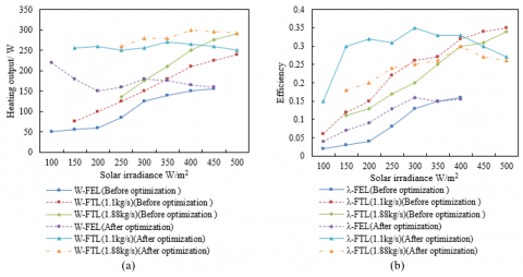
From Figure 6(a), it is observed that before optimization, W-FEL increases from 50 to 155 as solar irradiance increases. After optimization, W-FEL heating output significantly increases in the low irradiance range (100-200), reaching a range of 220 to 150, then decreases with increased irradiance, and later maintains relative stability in the 160-180 range. Before optimization, at a flow rate of 1.1kg/s, W-FTL heating output increases from 75 to 240 with increasing irradiance. After optimization, at a flow rate of 1.1kg/s, W-FTL heating output significantly increases across all irradiance ranges, especially in lower irradiance ranges, increasing from 255 to 270, and slightly decreases at higher irradiance. Before optimization, at a flow rate of 1.88kg/s, W-FTL increases from 135 to 290 with irradiance. After optimization, at a flow rate of 1.88kg/s, W-FTL overall heating output improves across all irradiance ranges, especially in mid to high irradiance ranges (300-500), maintaining between 280 to 300, showing the stability of system performance after optimization. It can be concluded that the optimized system exhibits higher heating output than before optimization at different flow rates, especially at lower solar irradiance. This indicates that the optimization scheme significantly improves system performance under various operating conditions. The FEL strategy, in particular, performs exceptionally well in low irradiance ranges after optimization. This is due to the optimization scheme enhancing collection efficiency or improving the system's adaptability to low irradiance conditions. For the FTL strategy at two different flow rates, system performance significantly improves across all irradiance ranges after optimization. This indicates that the proposed optimization measures enhance the overall heating capability of the system, regardless of the load conditions. Analyzing the heating output validates the effectiveness of the optimization scheme proposed in the paper in real-world applications. The system not only increases heating output after optimization but also maintains good performance stability across a wider range of irradiance.
Figure 5. Temperature changes at different measurement points in the collection system before and after integration and operational optimization improvements with variations in solar irradiance
Figure 6. Changes in heating output and efficiency of the solar thermal system before and after integration and operational optimization with variations in solar irradiance
From Figure 6(b), it is seen that before optimization, λ-FEL increases from 0.02 to 0.16, gradually improving efficiency as solar irradiance increases. After optimization, λ-FEL significantly improves at low irradiance, increasing from 0.04 to 0.155, with less noticeable efficiency improvement at higher irradiance. Before optimization, at a flow rate of 1.1kg/s, λ-FTL increases from 0.06 to 0.35, improving efficiency with increasing solar irradiance. After optimization, at a flow rate of 1.1kg/s, λ-FTL significantly improves across all irradiance ranges, especially at lower irradiance, jumping from 0.15 to over 0.3, and reaching a peak of 0.35 in the medium irradiance range, with a slight decrease in efficiency afterwards. Before optimization, at a flow rate of 1.88kg/s, λ-FTL increases from 0.11 to 0.34 as irradiance increases. After optimization, at a flow rate of 1.88kg/s, λ-FTL improvements are significant across all irradiance ranges, especially at lower irradiance, with efficiency improving to 0.18-0.2, then gradually increasing with irradiance, and slightly decreasing at high irradiance ranges but overall maintaining a high level. It can be concluded that the optimized system, under both FEL and FTL strategies, shows significantly improved collection efficiency across different irradiance levels. This demonstrates that the optimization measures effectively enhance the ability of solar energy to be converted into useful energy. The optimization improvements for the FEL strategy are particularly noticeable at lower irradiance. This means the system's performance under low light conditions is significantly enhanced, which is particularly important in conditions of insufficient sunlight such as cloudy days or during early morning and late evening. The FTL strategy shows efficiency improvements for both flow rates. At a low flow rate of 1.1kg/s, the efficiency improvement is particularly significant, due to the optimized system being more adaptable to different operating conditions. For a high flow rate of 1.88kg/s, efficiency improvements are also significant, especially at lower irradiance, indicating that optimization measures also enhance system performance under high demand conditions.
(a) Continuous cycle
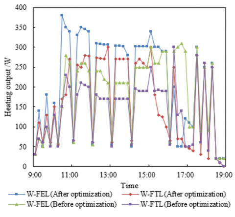
(b) Intermittent cycle
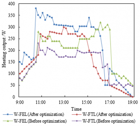
Figure 7. Changes in heating output of the system under different operating modes
By comparing the data from Figure 7, the performance of the solar-powered building electrical system under two operating modes, continuous and intermittent cycles, can be analyzed. It is noted that under the continuous cycle mode, W-FEL (after optimization) sees significant increases in heating output at certain times, such as from 80 to 150 at 9:00, and from 50 to 0 at 19:00. This indicates that the optimization scheme improves system efficiency during most time periods. W-FTL (after optimization) also shows an increase in heating output at most points, especially during high-demand periods, such as at 11:00 and 13:00, where heating output rises from 200 and 180 to 270 and 255, respectively. Under the intermittent cycle mode, changes in W-FEL (after optimization) are not very significant at most points but show a great increase in peak times, such as from 150 to 380 at 15:00, demonstrating the optimization scheme significantly enhances peak supply capacity. W-FTL (after optimization) also increases in heating output at peak times like 11:00 and 13:00, with little to no change or slight decreases at other times. It can be concluded that the optimization scheme significantly enhances the performance of the solar electrical system in continuous cycle mode, especially during periods of high electrical and thermal loads. In the intermittent cycle, the optimized system also shows stronger heating capabilities during peak times, but the improvement in non-peak periods is not very noticeable. The optimization scheme focuses on enhancing the system's heating capability during high demand peaks, helping to utilize solar energy resources more effectively and provide stronger support when energy demand is high.
The paper first conducts a detailed study on the thermodynamic efficiency of the solar electrical system through energy and exergy analysis methods. It assesses the energy losses and irreversibility in the solar conversion process, identifying key factors affecting system efficiency, such as solar irradiance, ambient temperature, and cooling water temperature. An integrated design and operational optimization scheme is proposed, setting optimization objectives and establishing a set of comprehensive evaluation standards. Sensitivity analysis is conducted to determine the main influencing parameters on the efficiency of the solar thermal system.
The paper analyzes the temperature changes at different measurement points in the collection system before and after improvement with variations in solar irradiance. It compares the changes in heating output and efficiency before and after optimization with variations in solar irradiance. The changes in heating output under two operating modes, continuous and intermittent cycles, are studied. Experimental results show that the optimization scheme significantly improves heating efficiency during high-demand periods, especially in continuous cycle mode. In intermittent cycle mode, the system also displays stronger heating capabilities during peak times, but improvements in non-peak periods are not very noticeable. Sensitivity analysis reveals the system's dependency on key parameters, providing data support for further system design.
In summary, this paper successfully proposes and validates an integration and operational optimization scheme for a solar-powered building electrical system, significantly enhancing the system's thermal efficiency. By employing thermodynamic analysis methods comprehensively, key factors affecting system efficiency are identified and optimized. Future research could further explore more efficient designs for solar collectors and how to better integrate the collection system with the building electrical system. More advanced control strategies can be developed to respond in real time to environmental changes and usage demands, achieving more refined energy management.
[1] Cui, Y., Zhao, H. (2023). Marine renewable energy project: The environmental implication and sustainable technology. Ocean & Coastal Management, 232: 106415. https://doi.org/10.1016/j.ocecoaman.2022.106415
[2] Chen, S. (2024). Renewable energy technology innovation and urbanization: Insights from China. Sustainable Cities and Society, 102: 105241. https://doi.org/10.1016/j.scs.2024.105241
[3] Hao, Y., Li, X., Murshed, M. (2023). Role of environmental regulation and renewable energy technology innovation in carbon neutrality: A sustainable investigation from China. Energy Strategy Reviews, 48: 101114. https://doi.org/10.1016/j.esr.2023.101114
[4] Naimovičius, L., Bharmoria, P., Moth-Poulsen, K. (2023). Triplet–triplet annihilation mediated photon upconversion solar energy systems. Materials chemistry frontiers, 7(12): 2297-2315. https://doi.org/10.1039/D3QM00069A
[5] Sutikno, T., Samosir, A.S., Aprilianto, R.A., Purnama, H. S., Arsadiando, W., Padmanaban, S. (2023). Advanced DC–DC converter topologies for solar energy harvesting applications: A review. Clean Energy, 7(3): 555-570. https://doi.org/10.1093/ce/zkad003
[6] Gevorgian, A., Pernigotto, G., Gasparella, A. (2023). Machine learning techniques and 3D GIS building model for accurate solar radiation prediction on building facades in mountainous and urban regions. In Proceedings of the 18th IBPSA Conference, Shanghai, China, pp. 1113-1120. https://doi.org/10.26868/25222708.2023.1300
[7] Sagade, A.A., Sagade, N.A., Belgasim, B., Tawfik, M.A., Kulkarni, S., Shulka, S.K. (2023). Building integrated innovative non-imaging concentrating solar collector for clean cooking under low sun elevation. Sustainable Energy Technologies and Assessments, 57: 103234. https://doi.org/10.1016/j.seta.2023.103234
[8] Huang, X.Y., He, J.W., Huang, Y.X., Cai, Y., Wang, W.W., Zhao, F.Y. (2023). Numerical analysis of solar ventilated façade integrated thermoelectric energy harvesting panel for simultaneous building thermal insulation and power generation. Journal of Building Engineering, 76: 107304. https://doi.org/10.1016/j.jobe.2023.107304
[9] Allouhi, A., Amine, M.B., Reisch, C. (2023). Multi-objective optimization of solar energy systems for electricity and hot water generation in collective residential buildings considering the power-to-heat concept. Applied Thermal Engineering, 230: 120658. https://doi.org/10.1016/j.applthermaleng.2023.120658
[10] Bosu, I., Mahmoud, H., Ookawara, S., Hassan, H. (2023). Applied single and hybrid solar energy techniques for building energy consumption and thermal comfort: A comprehensive review. Solar Energy, 259: 188-228. https://doi.org/10.1016/j.solener.2023.05.006
[11] Gürbüz, H., Demirtürk, S., Akçay, H., Topalcı, Ü. (2023). Experimental investigation on electrical power and thermal energy storage performance of a solar hybrid PV/T-PCM energy conversion system. Journal of Building Engineering, 69: 106271. https://doi.org/10.1016/j.jobe.2023.106271
[12] Chandrasekar, M. (2023). Building-integrated solar photovoltaic thermal (BIPVT) technology: a review on the design innovations, aesthetic values, performance limits, storage options and policies. Advances in Building Energy Research, 17(2): 223-254. https://doi.org/10.1080/17512549.2023.2185675
[13] Alim, M.A., Tao, Z., Saeed, N., Hao, X., Abden, M. J., Rahman, A. (2022). Effect of reflective coating on thermal and electrical performances of solar roof tiles. Energy Conversion and Management, 270: 116251. https://doi.org/10.1016/j.enconman.2022.116251
[14] Miglioli, A., Aste, N., Del Pero, C., Leonforte, F. (2023). Photovoltaic-thermal solar-assisted heat pump systems for building applications: Integration and design methods. Energy and Built Environment, 4(1): 39-56. https://doi.org/10.1016/j.enbenv.2021.07.002
[15] Rotas, R., Fotopoulou, M., Drosatos, P., Rakopoulos, D., Nikolopoulos, N. (2023). Adaptive dynamic building envelopes with solar power components: Annual performance assessment for two pilot sites. Energies, 16(5): 2148. https://doi.org/10.3390/en16052148
[16] Liang, S., Zheng, H., Liu, S., Ma, X. (2022). Optical design and validation of a solar concentrating photovoltaic-thermal (CPV-T) module for building louvers. Energy, 239: 122256. https://doi.org/10.1016/j.energy.2021.122256
[17] Aneli, S., Arena, R., Tina, G.M., Gagliano, A. (2023). Improvement of energy self-sufficiency in residential buildings by using solar-assisted heat pumps and thermal and electrical storage. Sustainable Energy Technologies and Assessments, 60: 103446. https://doi.org/10.1016/j.seta.2023.103446
[18] Wang, F., You, T. (2023). Synergetic performance improvement of a novel building integrated photovoltaic/thermal-energy pile system for co-utilization of solar and shallow-geothermal energy. Energy Conversion and Management, 288: 117116. https://doi.org/10.1016/j.enconman.2023.117116
[19] Amara, M.B., Balghouthi, M. (2023). Colored filter's impact on the solar cells' electric output under real climatic conditions for application in building integrated photovoltaics. Journal of Building Engineering, 76: 107276. https://doi.org/10.1016/j.jobe.2023.107276
[20] Jalalizadeh, M., Fayaz, R., Delfani, S., Mosleh, H.J., Karami, M. (2021). Dynamic simulation of a trigeneration system using an absorption cooling system and building integrated photovoltaic thermal solar collectors. Journal of Building Engineering, 43: 102482. https://doi.org/10.1016/j.jobe.2021.102482