Tingting Cheng![]()
© 2024 The author. This article is published by IIETA and is licensed under the CC BY 4.0 license (http://creativecommons.org/licenses/by/4.0/).
OPEN ACCESS
With escalating environmental standards and the pursuit of energy efficiency, Gasoline Direct Injection (GDI) technology has become crucial for enhancing engine performance and reducing emissions. As a vital component of the engine, the design of the piston ring significantly influences the thermodynamic performance of the engine. This paper systematically studies the thermodynamic impact of piston ring gaps in GDI engines. Initially, through the analysis of heat transfer and piston strength associated with piston ring gaps, the effects on engine thermal efficiency and structural stability are explored. Subsequently, by integrating three different thermal analysis boundary conditions and mechanical load conditions, we assess how these variables affect the piston’s thermal state and engine performance. Existing studies, often relying on simplified models or empirical formulas, tend to overlook the complex thermodynamic and mechanical interactions under actual operating conditions, resulting in inadequate predictive accuracy. This research introduces more complex boundary condition simulations, aiming to provide a more precise method for predicting piston performance, thus offering theoretical support and practical guidance for the optimization of GDI engine design. This study not only fills the research gap regarding piston ring gaps but also provides new perspectives and data support for engine design and optimization, contributing to the advancement of efficient, low-emission engine technologies.
Gasoline Direct Injection (GDI) technology, piston rings, thermodynamic performance, heat transfer analysis, boundary conditions
In recent years, with increasingly stringent environmental protection requirements and the continuous improvement of fuel economy, GDI technology has been widely applied due to its excellent dynamic performance and potential to reduce emissions [1-3]. As an important component of the engine, the structure and gap of the piston rings directly affect the thermodynamic efficiency and overall performance of the engine. Optimization of piston ring gaps not only improves fuel combustion efficiency but also reduces emissions of oil and gas, and is one of the key factors in enhancing the performance of GDI engines [4-7].
For GDI engines, the design and performance analysis of piston rings holds significant research importance. Studying the impact of piston ring gaps on the thermodynamic performance of engines can provide theoretical bases and data support for engine design, further optimizing engine structure, and enhancing its efficiency and environmental adaptability [8, 9]. Additionally, accurate piston thermal analysis can effectively predict performance changes of the engine under different operating conditions, providing a scientific basis for studies on engine reliability and durability [10-12].
However, existing studies often focus on empirical models and simplified calculation methods, which tend to overlook the complex thermodynamic and mechanical interactions, making it difficult to accurately predict the behavior of piston components under extreme conditions [13-15]. Moreover, the settings of boundary conditions are often too idealized, failing to fully reflect the complexity of the actual operating environment, thus affecting the accuracy and practicality of model predictions [16].
This paper primarily studies two aspects: firstly, by analyzing the heat transfer and piston strength associated with piston ring gaps in GDI engines, it explores how variations in gaps affect the thermodynamic performance of the engine; secondly, regarding piston thermal analysis, this paper will consider three different boundary conditions and mechanical load conditions to simulate the environment more accurately under actual operating conditions. These studies not only fill the gaps in existing research but also provide more precise and practical design references, offering theoretical and technical support for the optimization and performance enhancement of GDI engines. Through these in-depth analyses, this paper aims to further advance GDI engine technology, achieving higher energy efficiency and lower emissions.
2.1 Heat transfer analysis
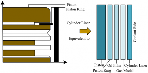
The gap of piston rings significantly impacts the thermodynamic performance of GDI engines, especially in terms of heat transfer analysis. Optimizing the piston ring gap can effectively regulate the internal heat flow and thermal losses within the engine, thereby affecting the combustion efficiency and overall thermal efficiency. Detailed heat transfer analysis of piston ring gaps can reveal how different gap sizes influence the fuel combustion process, as well as the distribution and transfer of heat. Such analysis aids in understanding how piston ring gaps adjust thermal energy losses under different operating conditions, providing theoretical basis and data support for designing more efficient engines. This not only optimizes engine energy efficiency but also reduces harmful emissions, enhancing the engine’s environmental adaptability and economic performance. Figure 1 shows the heat transfer model of a piston in a GDI engine.
In GDI engines, thermal management of the piston is particularly critical because direct fuel injection causes higher local combustion temperatures. Compared to conventional engines, the piston tops in GDI engines not only receive high temperature heat flows from the combustion chamber but must also cope with more complex and intense thermal loads. For this reason, the design of piston ring gaps plays a key role in GDI engines. These gaps not only provide necessary allowances for thermal expansion but also affect the paths of heat conduction, thereby regulating the heat flow from the piston top to the bottom. In effective thermal management strategies, pistons are often equipped with internal cooling oil chambers, where the injection of cooling oil not only enhances cooling efficiency but also helps reduce thermal stress on the piston and piston rings, further increasing the engine’s thermal efficiency and mechanical stability.
Figure 1. Heat transfer model of a piston in a GDI engine
In the heat transfer analysis of the piston ring gaps in a GDI engine, constructing the heat conduction differential equation is one of the key steps, based on the fundamental principles of Fourier's law and energy conservation. Fourier's law describes the flow of heat through a conductor as being proportional to the temperature gradient, i.e., the relationship between heat flux density and temperature gradient. During the heat transfer process in piston ring gaps, heat moves from the high-temperature piston top through the solid piston material to relatively cooler parts. This process can be expressed by a heat conduction differential equation that considers the temporal and spatial changes in the heat transfer process. Assume the density of the control volume is represented by ϑ, the specific heat capacity by z, the thermal conductivity within the control volume by η, and the heat generated per unit time and volume by Θ. The constructed heat conduction differential equation is as follows:
$\vartheta z\frac{\partial S}{\partial s}=\frac{\partial }{\partial a}\left( \eta \frac{\partial S}{\partial a} \right)+\frac{\partial }{\partial b}\left( \eta \frac{\partial S}{\partial b} \right)+\frac{\partial }{\partial c}\left( \eta \frac{\partial S}{\partial c} \right)+\Theta $ (1)
Although the interior of a piston in a GDI engine does not directly contain a heat source, compared to traditional engines, pistons in direct injection engines endure higher thermal loads due to the direct injection of fuel into the combustion chamber. Therefore, while constructing the heat conduction differential equation for piston ring gaps in a GDI engine, it may be simplified as a heat conduction process without internal heat sources, but it must consider the inhomogeneity of the temperature field and higher local temperature gradients caused by direct fuel injection. The simplified heat conduction differential equation should reflect the heat conduction path from the top to the bottom of the piston and take into account the thermal conductivity of the piston material and the actual conditions of boundary conditions, such as the temperature and flow rate of the cooling oil.
$\vartheta z\frac{\partial S}{\partial s}=\eta \left( \frac{{{\partial }^{2}}S}{\partial {{a}^{2}}}+\frac{{{\partial }^{2}}S}{\partial {{b}^{2}}}+\frac{{{\partial }^{2}}S}{\partial {{c}^{2}}} \right)$ (2)
Considering the uniqueness of the operating environment for pistons in GDI engines, heat transfer analysis is often set as a steady-state process to simplify the heat conduction differential equation of the piston ring gaps. This paper assumes that the heat transfer coefficient remains constant throughout the operation cycle, meaning it disregards potential transient fluctuations in heat transfer, focusing on the distribution and impact of steady-state heat flow. Because frequent fuel injections and high-temperature combustion lead to an extremely complex temperature field, this simplification helps in accurately predicting and assessing the stability of heat transfer between the piston top and ring gaps.
$\frac{{{\partial }^{2}}S}{\partial {{a}^{2}}}+\frac{{{\partial }^{2}}S}{\partial {{b}^{2}}}+\frac{{{\partial }^{2}}S}{\partial {{c}^{2}}}=0$ (3)
2.2 Piston strength analysis
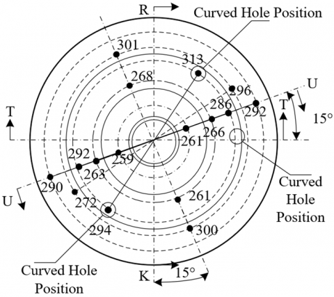
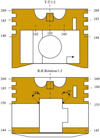
This paper further carries out a study on piston strength analysis. In the high temperature and high pressure working environment of the engine, the mechanical strength and durability of the piston directly affect the reliability and lifespan of the engine. Through systematic analysis of piston strength, the performance of pistons under different materials, designs, and processing conditions can be assessed, especially their structural stability under extreme conditions. This analysis helps in optimizing the design of pistons, selecting appropriate materials and manufacturing processes to withstand the effects of high temperatures and high stresses. Figure 2 shows a test sample oriented towards piston strength analysis.
Figure 2. Test sample for piston strength analysis
In the piston ring strength analysis of GDI engines, this paper uses the fourth strength theory (Mises strength theory) to predict the structural stability and failure risk of piston rings under complex load conditions. The Mises strength theory is based on the equivalent stress of the stress state to assess material yield, which is particularly suitable for dealing with multiaxial stress states under the conditions of high-speed operation and high-pressure combustion of engines. In GDI engines, piston rings endure thermal and mechanical stresses far beyond those of traditional engines, as direct fuel injection leads to higher local temperatures and pressures. By applying the Mises strength theory, the behavior of piston rings under these high-stress conditions can be accurately analyzed, predicting potential points of brittle fracture or plastic yielding, thereby designing more durable and reliable piston rings. Assume that the shape change energy ratio is represented by ia, the first principal stress by δ1, the second principal stress by δ2, and the third principal stress by δ3, and the material's modulus of elasticity by R. The shape change energy of the piston ring under complex stress can be calculated as follows:
${{i}_{a}}=\frac{1+\omega }{6R}\left[ {{\left( {{\delta }_{1}}-{{\delta }_{2}} \right)}^{2}}+{{\left( {{\delta }_{2}}-{{\delta }_{3}} \right)}^{2}}+{{\left( {{\delta }_{3}}-{{\delta }_{1}} \right)}^{2}} \right]$ (4)
Assuming the material's Mises stress is represented by δt, the allowable stress by [δ], with δ1≥δ2≥δ3. The stress yield condition can be characterized by the following equation:
${{\delta }_{s}}=\sqrt{\frac{1}{2}\left[ {{\left( {{\delta }_{1}}-{{\delta }_{2}} \right)}^{2}}+{{\left( {{\delta }_{2}}-{{\delta }_{3}} \right)}^{2}}+{{\left( {{\delta }_{3}}-{{\delta }_{1}} \right)}^{2}} \right]}\le \left[ \delta \right]$ (5)
In studying the thermal analysis of pistons in GDI engines, considering appropriate boundary conditions is crucial, as they directly impact the accuracy and reliability of thermal simulations. This paper conducts a detailed study of three types of boundary conditions: fixed temperature boundary conditions, fixed heat flux boundary conditions, and convective heat exchange boundary conditions. These conditions simulate the behavior of the piston under different thermal environments, such as the direct impact of the coolant environment, thermal interactions between the piston and combustion gases, and heat radiation or convective losses on the piston surface. Such categorical research aids in precisely describing and predicting the temperature distribution and thermal stresses of the piston during actual operation, providing key data for optimizing engine design, particularly in enhancing thermal efficiency and reducing the risk of overheating.
On the other hand, the study of mechanical load boundary conditions focuses on the mechanical forces acting on the piston, which are crucial for assessing the piston's structural integrity and durability. In GDI engines, the piston withstands periodic loads from high-pressure combustion gases in the combustion chamber, as well as mechanical friction with the cylinder walls and piston rings. Clarifying the magnitude and distribution of these loads, and how they change with operating conditions, is key to designing pistons that can withstand high temperatures and pressures, thereby extending the engine's lifespan. This research, by simulating different mechanical load scenarios, reveals the specific impacts of these conditions on the piston's thermal behavior and physical fatigue, further enhancing understanding of the engine's overall performance and reliability, and aiding in the advancement of engine technology.
3.1 Heat transfer boundary theory
Figure 3. Piston heat transfer temperature field testing situation
In GDI engines, the internal cooling mechanisms of the piston are crucial for its performance and durability, especially in high-pressure and high-temperature combustion environments. Compared to traditional engines, pistons in GDI engines endure more intense and uneven thermal loads, making the heat transfer process of the piston ring gaps and their accurate calculation particularly important. According to Newton's Law of Cooling, the heat transfer between the cooling oil and the inner oil chamber walls of the piston can be calculated based on the convective heat transfer coefficient of the coolant, and the temperature difference between the piston wall and the coolant. The key to this process is determining an effective convective heat transfer coefficient and accurately measuring or estimating the temperature gradient between the wall and the coolant, involving steady-state analysis and transient response analysis of heat transfer to ensure optimal thermal performance and structural integrity of the piston under the harshest conditions. Figure 3 shows the testing situation of the piston heat transfer temperature field. Assuming that the heat exchange between the fluid and the solid surface is represented by wq, the heat exchange coefficient between the fluid and the solid surface by j, the temperature of the fluid flowing over the solid surface by Sd, and the solid surface temperature by Sq, the calculation formula is:
${{w}_{q}}=j\left( {{S}_{d}}-{{S}_{q}} \right)$ (6)
The boundary conditions for the thermal analysis of pistons in GDI engines are categorized into three types:
The first type of thermal boundary condition specifies the temperature of the piston ring gap surface. This is usually based on the actual temperature of the piston top in contact with the combustion chamber, which is significantly influenced by the high temperatures caused by direct fuel injection. Thus, the boundary temperature can be set as a constant or as a function varying with engine operating parameters, to accurately reflect the thermal environment under actual operating conditions. The setting of this boundary condition is particularly critical for simulating the thermal load distribution at the piston top, as it directly affects engine performance and the thermal stress response of piston materials. Assuming $\text{Ξ}$ represents the boundary, the function expression is as follows:
$\left.S\right|_{\Xi}=d\,(a, b, c, s)$ (7)
The second type of thermal boundary condition involves the heat flux density at the boundary, which is also crucial for the thermal analysis of piston ring gaps in GDI engines. In this case, the heat flux density might be set based on the heat conduction model from the piston top to the ring gap, which includes direct transfer of heat during the combustion process and local temperature increases caused by fuel injection. This heat flux density is typically set as a constant or as a function that changes with engine operating conditions, allowing the model to precisely calculate how heat is transferred from high-temperature areas to cooler regions. The function expression is as follows:
$-j\frac{\partial S}{\partial v}\left| _{\Xi } \right.=h\left( a,b,c,s \right)$ (8)
The third type of thermal boundary condition specifies the surface heat transfer coefficient between the piston and the surrounding fluid, as well as the temperature of the surrounding fluid. This boundary condition is fundamental for simulating the convective heat exchange during the piston cooling process. Considering the extreme temperatures that pistons in direct injection engines may encounter, this simulation of convective heat transfer is crucial for ensuring the reliability and safety of the piston during extended operation. Proper selection of the heat transfer coefficient and fluid temperature can help more accurately predict and control piston temperature, thus optimizing engine design and enhancing efficiency. Assuming the convective heat transfer coefficient is represented by g, and the wall temperature by S, the function expression is as follows:
$-j\frac{\partial S}{\partial v}\left| _{\Xi } \right.=g\left( S-{{S}_{d}} \right)\left| _{\Xi } \right.$ (9)
3.2 Three types of boundary conditions for piston thermal analysis
Although pistons experience complex variations in temperature and heat transfer coefficients during the working cycle, these changes are brief, primarily manifesting as steady-state thermal loads. Integrating the three types of boundary conditions applicable to the thermal analysis of piston ring gaps in GDI engines, further calculations are performed on relevant parameters.
(1) Average Heat Transfer Coefficient and Average Gas Temperature
Since the temperature and pressure peaks caused by direct injection technology are more intense and transient compared to traditional engines, it is necessary to capture these rapidly changing thermal dynamics more meticulously to ensure that the thermal analysis of piston ring gaps accurately reflects the thermal loads and efficiency under actual operating conditions. For this purpose, the calculation of the average heat transfer coefficient and average gas temperature employs the modified Eichelberg formula. This study calculates the gas heat transfer coefficient βh for each crankshaft angle, a step particularly suited to the rapidly changing combustion conditions in direct injection technology. Assuming the correction factor is represented by j0, the average velocity by Zl, the instantaneous gas pressure by Oh, and the instantaneous gas temperature by Sh, the calculation formula is:
${{\beta }_{h}}={{j}_{0}}\sqrt[3]{{{Z}_{l}}}\sqrt{{{O}_{h}}{{S}_{h}}}$ (10)
Subsequently, by integrating over the entire working cycle, the average heat transfer coefficient βhl inside the cylinder is obtained.
${{\beta }_{hl}}=\frac{1}{4\pi }\int_{0}^{4\pi }{{{\beta }_{h}}{{f}_{\psi }}}$ (11)
Similarly, the average gas temperature Shl is also obtained through the integral average of temperatures within the cycle.
${{T}_{gm}}=\frac{1}{4\pi }\int_{0}^{4\pi }{{{T}_{g}}{{d}_{\phi }}}$ (12)
(2) Piston Top Surface Heat Transfer Coefficient
Due to the specificity of its injection and combustion modes, the heat transfer coefficient on the piston top surface in GDI technology exhibits spatial distribution characteristics different from those in traditional engines. The heat transfer coefficient depends not only on the radial distance r from various points on the piston top to the center but also shows nonlinear variation characteristics. Specifically, the heat transfer coefficient exhibits one trend when the distance r is less than the distance V from the piston center to the position of the maximum heat transfer coefficient; when r is greater than V, it displays a different variation pattern. This piecewise function description allows for more accurate simulation and analysis of the heat flow changes caused by direct fuel injection and combustion at different parts of the piston top under high-pressure combustion conditions. Assuming the average heat transfer coefficient inside the cylinder is represented by xhl, the distance from the piston center by e, and the distance from the piston center to the maximum heat transfer coefficient position by V. The calculation formula when r < V is:
${{\beta }_{e}}=\frac{2{{\beta }_{hl}}}{1+{{e}^{0.1{{\left[ \frac{V}{25.4} \right]}^{1.5}}}}}{{e}^{0.1}}{{\left[ \frac{r}{25.4} \right]}^{1.5}}$ (13)
And when r > V, the calculation formula is:
${{\beta }_{r}}=\frac{2{{\beta }_{hl}}}{1+{{e}^{0.1{{\left[ \frac{V}{25.4} \right]}^{1.5}}}}}{{e}^{0.1}}{{\left[ \frac{2V-r}{25.4} \right]}^{1.5}}$ (14)
(3) Heat Transfer Coefficients for Piston Ring Grooves and Skirt Surface
Accurately calculating the heat transfer coefficients for the piston ring grooves, the fire lands, and the skirt is crucial for assessing the overall thermal behavior of the piston in GDI engine thermal analysis. These areas face different thermal loads and cooling requirements due to their position and function within the piston. The heat transfer coefficient for the piston ring groove area (β1), which often involves parts in direct contact with combustion gases and is directly affected by high-frequency fuel injection, may be higher than in traditional engines. The heat transfer coefficient for the piston skirt (β2), involving the contact surface between the piston and the cylinder wall, must also consider additional heat flow caused by high-pressure injection in GDI engines. The heat transfer coefficient for the fire land (β3) describes the part of the piston closest to the combustion area, directly exposed to extreme temperatures and pressures. Calculating these area-specific heat transfer coefficients using applicable empirical formulas can better understand the thermal stress and heat transfer characteristics of each part during engine operation, thus optimizing piston design and ensuring stability and efficiency under high load and high-temperature conditions. Assuming the thermal conductivities for the piston ring, oil film, and cylinder liner are represented by λ1, λ2, λ3, and their thicknesses by x, y, z respectively, the heat transfer coefficient between the cylinder liner and the cooling water by ημ, and the gap between the cylinder liner and the piston ring by ∆v, the calculation formula for β1 is:
${{\beta }_{1}}={{\left( \frac{x}{{{\eta }_{1}}}+\frac{y}{{{\eta }_{2}}}+\frac{y}{{{\eta }_{3}}}+\frac{1}{{{\eta }_{\mu }}} \right)}^{-1}}$ (15)
The calculation formula for β2 is:
${{\beta }_{2}}={{\left( \frac{y}{{{\eta }_{2}}}+\frac{y}{{{\eta }_{3}}}+\frac{1}{{{\eta }_{\mu }}} \right)}^{-1}}$ (16)
The calculation formula for β3 is:
${{\beta }_{3}}={{\left( \frac{\Delta v}{{{\eta }_{1}}}+\frac{y}{{{\eta }_{3}}}+\frac{1}{{{\eta }_{\omega }}} \right)}^{-1}}$ (17)
(4) Heat Transfer Coefficient of the Piston Interior
In the thermal analysis of piston ring gaps in GDI engines, the stability of the heat transfer coefficient within the piston cavity is crucial for accurately simulating the internal thermal behavior of the piston. Compared to traditional engines, the piston cavity in GDI engines faces a more complex thermal environment due to direct fuel injection into the combustion chamber, experiencing higher temperature gradients and pressure changes. Despite this, the heat transfer coefficient within the piston cavity is generally stable and can be calculated using applicable empirical formulas that consider the impact of direct injection characteristics on heat transfer. This empirical calculation method allows engineers to quickly assess and optimize the cooling performance of the piston interior, ensuring thermal stress remains within controllable limits while enhancing the overall thermal efficiency of the engine. Assuming the thickness of the piston top by σ, the thermal conductivity of the piston by η, the top temperature of the piston by S1, the bottom temperature of the piston cavity by S2, and the temperature inside the crankcase by Sv, the calculation formula is:
${{\beta }_{v}}=\frac{\left( {{S}_{1}}-{{S}_{2}} \right)\eta }{\left( {{S}_{2}}-{{S}_{v}} \right)\sigma }$ (18)
(5) Heat Transfer Coefficient of the Piston's Internal Oil Chamber
The heat transfer coefficient of the internal oil chamber in GDI engines can also be calculated using empirical formulas that take into account the specific high-temperature and high-pressure conditions associated with direct injection technology. Unlike traditional engines, pistons in GDI engines experience more intense temperature fluctuations and higher pressures, making the design and evaluation of the heat transfer performance of the internal oil chamber more complex. Empirical formulas need to be calibrated based on actual measurement data and advanced thermal fluid simulation technologies to ensure that the cooling efficiency inside the piston meets the cooling demands under extreme operating conditions. Assuming the equivalent diameter is represented by F*, the average heat transfer coefficient by g, the Prandtl number by Oed, the Nusselt number by Vid, the thermal conductivity of the oil by η0, and the average height of the oil chamber by y, the calculation formulas are:
$\begin{align} & {{V}_{id}}=0.495E_{rd}^{0.57}{{F}^{*0.24}}O_{ed}^{0.29} \\ & {{F}^{*}}=\frac{F}{y} \\ & {{V}_{id}}=\frac{gf}{{{\eta }_{0}}} \\\end{align}$ (19)
3.3 Mechanical load boundary conditions for pistons
In the thermal analysis of piston ring gaps in GDI engines, in addition to thermal loads, the piston also endures complex mechanical loads, and the interaction of these two physical fields significantly impacts the piston's performance and durability. For this reason, it is crucial to use a sequential coupling method, taking the piston's steady-state temperature field as a known condition and coupling it with mechanical loads for calculations. The piston experiences extreme mechanical stresses during its operational cycle, especially under the high gas pressures caused by direct fuel injection into the combustion chamber and at moments of maximum inertial forces at the top and bottom dead centers. For example, under the maximum burst pressure condition Pmax, the bottom face of the first ring groove and the area below it endure a pressure of 0.75 Pmax, while the first ring land and the area above and below the second ring groove experience a pressure of 0.25 Pmax, with the bottom face of the second ring groove set to a pressure of 0.2 Pmax. Such distribution of mechanical loads, combined with corresponding accelerations, ensures accurate simulation of the mechanical and thermal stresses the piston undergoes under actual operating conditions. Additionally, for different operating conditions (such as idle, medium load, and full load), thermal-mechanical coupled fields are simulated under maximum cylinder pressures of 5 MPa, 7 MPa, and 9 MPa, respectively, to ensure optimization of performance and assessment of structural integrity of the GDI engine pistons under various pressure and temperature conditions. This coupled analysis helps designers gain a deeper understanding of the complex thermomechanical behavior of piston ring gaps, providing more precise data support for engine design.
The data presented in Table 1 shows the thermal boundary conditions experienced by various parts of a piston in a GDI engine, including heat transfer coefficients and ambient temperatures. From the table, it is evident that there are significant differences in the thermal loads faced by different parts of the piston. For example, the piston top surface (top and combustion face) has a heat transfer coefficient of 600 W/m²·℃ with an ambient temperature of 678℃, indicating a very high thermal load due to direct contact with combustion gases. In contrast, the skirt has a heat transfer coefficient of 800 W/m²·℃ but an ambient temperature of only 75.8℃, reflecting a significantly lower thermal load compared to the top, despite its higher heat transfer coefficient. The upper surface of the second ring has the highest heat transfer coefficient at 1987 W/m²·℃ with an ambient temperature of only 125℃, indicating strong heat transfer effects at this location, even though the ambient temperature is lower.
From the analysis of these data, it can be concluded that the differences in thermal loads borne by various parts of the piston and their impact on the overall thermodynamic performance are very significant. This is particularly important in the design and optimization of GDI engines. Areas of high thermal load such as the piston top and the upper surface of the second ring require special attention to prevent excessive temperatures that could lead to thermal damage or failure of the piston.
Table 1. Thermal boundary conditions of piston rings in a GDI engine
|
Boundary |
Heat Transfer Coefficient (W.m-2.℃-1) |
Ambient Temperature /℃ |
|
|
Piston Top Surface (top and combustion face) |
600 |
678 |
|
|
Fire Land |
50 |
425 |
|
|
1st Ring |
Upper Surface |
1425 |
426 |
|
Inner Surface |
81 |
315 |
|
|
Lower Surface |
458 |
235 |
|
|
1st Ring Land |
100 |
125 |
|
|
2nd Ring |
Upper Surface |
1987 |
125 |
|
Inner Surface |
100 |
125 |
|
|
Lower Surface |
3400 |
125 |
|
|
2nd Ring Land |
200 |
125 |
|
|
3rd Ring |
Upper Surface |
1458 |
114 |
|
Inner Surface |
200 |
114 |
|
|
Lower Surface |
1426 |
114 |
|
|
Piston Pin Bore |
500 |
75.8 |
|
|
Skirt |
800 |
75.8 |
|
|
Piston Interior |
Upper |
600 |
75.8 |
|
Middle |
500 |
75.8 |
|
|
Lower |
400 |
75.8 |
|
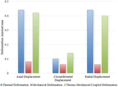
Figure 4. Comparison of deformation in GDI engine piston rings under thermal, mechanical, and thermo-mechanical coupled deformation
Figure 4 shows data reflecting axial, circumferential, and radial displacements of pistons in GDI engines under three conditions: thermal deformation, mechanical deformation, and thermo-mechanical coupled deformation. The data indicates that thermal deformation is more significant in axial and radial displacements, at 0.44 mm, while circumferential displacement is relatively smaller, at 0.1 mm. Mechanical deformation displays smaller displacements in all directions, averaging about 0.06 mm to 0.08 mm, suggesting that deformation under purely mechanical loading is limited. Thermo-mechanical coupled deformation data shows axial displacement at 0.42 mm, circumferential at 0.14 mm, and radial at 0.4 mm, indicating that under combined thermal and mechanical loads, the overall deformation of the piston is close to that of pure thermal deformation but slightly reduced. These results demonstrate that thermal loads play a dominant role in piston deformation, particularly in axial and radial deformations, while mechanical loads also cause some deformation, though their impact is relatively smaller. This finding emphasizes the importance of thermo-mechanical coupled analysis, as pistons in actual operating conditions are subjected to both thermal and mechanical loads. This study, by considering the complex boundary conditions and loading scenarios of pistons in actual operational environments, provides deformation data and analysis that is closer to reality, thereby helping to assess the thermodynamic performance and structural strength of pistons more accurately.
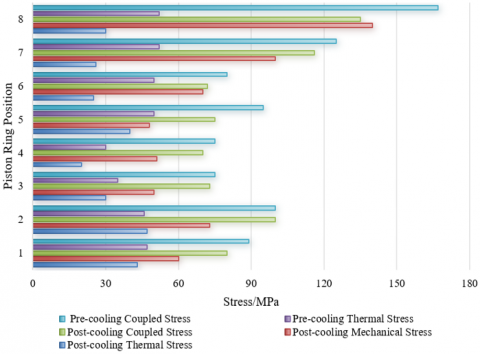
Figure 5. Comparison of piston ring stresses in GDI engines before and after oil chamber cooling
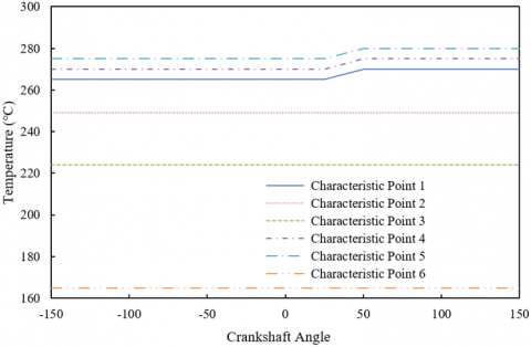
Figure 6. Temperature variations at different characteristic points in the piston ring gap of GDI engines
Figure 5 presents data comparing thermal stress, mechanical stress, and coupled stress of piston rings in GDI engines before and after oil chamber cooling. The data shows that thermal and coupled stresses before cooling are generally higher than those after cooling, with thermal stress at location 1 dropping from 47 MPa before cooling to 43 MPa after, and coupled stress dropping from 89 MPa to 80 MPa. However, mechanical stress in most locations shows a significant increase after cooling, particularly at location 8, rising from an unmentioned value before cooling to 140 MPa. This indicates that oil chamber cooling significantly reduces thermal and coupled stresses, but may increase mechanical stress in certain areas due to uneven material or structural responses. The results conclude that an increase in mechanical stress suggests a need to optimize cooling strategies in design and practical applications to prevent piston failure due to stress concentration. This research provides important insights into improving engine efficiency and reliability by systematically analyzing the thermodynamic performance and structural strength of piston rings.
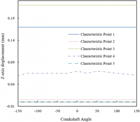
Figure 6 displays temperature change data at six characteristic points within the piston ring gap of GDI engines at different crankshaft angles. The data reveals that most characteristic points maintain a stable temperature throughout the observation period. For example, temperatures at characteristic points 1, 2, 3, and 6 remain consistent across all crankshaft angles, showing temperatures of 265℃, 249℃, 224℃, and 165℃, respectively. However, characteristic points 4 and 5 exhibit temperature increases at certain specific crank angles, with point 4 rising from 270℃ to 275℃, and point 5 from 275℃ to 280℃. This indicates that while most locations maintain stable temperatures throughout the operational cycle, temperatures at some locations vary with changes in crankshaft angle. These results highlight the position-dependent nature of temperature distribution in the piston ring gap, with some points potentially showing temperature increases influenced by crankshaft angle. This non-uniform distribution and variation of temperatures are crucial for understanding the thermal behavior of piston ring gaps in actual operation, especially in considering the balance and optimization of thermal loads during the design stage.
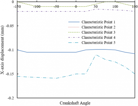
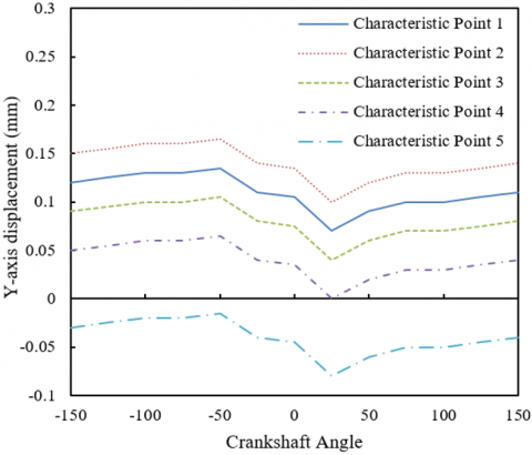
Figure 7. Axial displacement variation curves at different characteristic points in the piston ring gap of a GDI engine
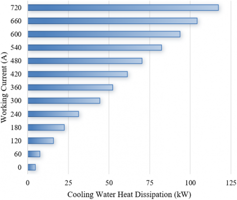
Figure 8. Cooling water heat dissipation in different steady-state conditions of the tested GDI engine
In the three sets of data presented in Figure 7, we observe significant differences in the axial displacement variations of different characteristic points in the piston ring gap of a GDI engine at various crankshaft angles. The first set of data shows that characteristic point 5 has the largest range of displacement changes, from -0.155 to -0.11, indicating that the displacement response at some characteristic points is very sensitive to changes in temperature or mechanical loads. In the second set of data, characteristic points 2 and 3 show relatively large positive displacements, where characteristic point 2 changes from 0.15 to 0.14 and characteristic point 3 from 0.09 to 0.08. The third set of data exhibits more stable displacement conditions, especially for characteristic points 1 and 3, where the displacements remain at fixed values of 0.17 and 0.22, respectively, showing that under certain conditions, some areas may be less affected or their displacements effectively controlled. These detailed displacement data allow for a deeper understanding of the dynamic behavior of the piston ring gap in actual working environments.
The data shown in Figure 8 reflects the heat dissipation of cooling water in a tested GDI engine under different working currents, where the range of working currents is from 0 to 720 mA, and the cooling water heat dissipation ranges from 4.7 to 117.2 W. The data shows a clear linear increase trend in cooling water heat dissipation as the working current increases. The heat dissipation is 7.6 W at 60 mA and rises to 117.2 W as the current increases to 720 mA. This gradual increasing trend indicates that the engine's thermal load is closely related to the increase in current, thereby affecting the thermal burden on the cooling system. Detailed analysis of this data leads to the conclusion that during the operation of the GDI engine, the required cooling capacity significantly increases with the load. This result validates the importance and accuracy of the thermal analysis and strength analysis methods used in the study, particularly when considering engine design and cooling system optimization. The cooling water heat dissipation data provide an empirical basis for engine temperature control and cooling system design, ensuring engine efficiency and safety under various operating conditions.
Table 2. Thermal balance analysis data measured in steady state test of the tested GDI engine
|
Working Current (A) |
Output Power (kW) |
Cooling Water Temperature Difference (℃) |
Cooling Water Flow Rate (m3/h) |
|
30.2 |
6.8 |
1.24 |
3.21 |
|
60.1 |
12.8 |
1.78 |
3.35 |
|
120.4 |
24.5 |
3.52 |
3.78 |
|
182.2 |
37.8 |
4.35 |
4.25 |
|
245.2 |
48.2 |
5.36 |
4.89 |
|
300.2 |
58.9 |
6.48 |
5.98 |
|
360.1 |
68.9 |
6.89 |
6.34 |
|
420.1 |
78.9 |
7.84 |
6.78 |
|
485.2 |
87.9 |
8.24 |
7.35 |
|
542.2 |
98.2 |
8.79 |
7.89 |
|
600.2 |
103.2 |
8.36 |
9.42 |
|
660.5 |
111.4 |
8.79 |
11.25 |
|
720.5 |
116.9 |
9.78 |
11.36 |
Table 2 provides the thermal balance analysis data for the tested GDI engine under various working current conditions, including output power, cooling water temperature difference, and cooling water flow rate. The data shows that as the working current increases, the output power increases from 6.8 kW to 116.9 kW, and the cooling water temperature difference and flow rate also increase accordingly. Specifically, the cooling water temperature difference rises from 1.24°C to 9.78°C, and the cooling water flow rate increases from 3.21 m³/h to 11.36 m³/h. This growth trend indicates that as the engine load increases, the cooling system must handle a greater thermal load, requiring more cooling water flow and a higher temperature difference for effective heat dissipation. From these data, it can be concluded that the thermal management strategy of the GDI engine must be optimized according to its operating conditions to maintain efficient operation and thermal balance under different loads. Effective cooling water management not only ensures the appropriate temperature of engine components but also helps to enhance overall thermal efficiency. Therefore, the thermal analysis and piston strength analysis conducted in this study provide valuable data support for engine design and optimization, confirming the accuracy and practicality of the methods through actual thermal balance data, and providing a scientific basis for the design and adjustment of the engine’s thermal management system.
This study systematically analyzes the thermodynamic behavior and mechanical response of the piston ring gap in GDI engines, through a series of experiments that evaluated the piston ring's thermal boundary conditions, deformation, stress responses, temperature distribution, and its displacement changes, as well as the overall thermal balance performance of the engine. Through detailed analysis of the piston ring thermal boundary conditions, we identified the areas of the piston top and ring gap that are most significantly affected by heat; deformation analysis of the piston ring revealed the response of the piston structure under thermal and mechanical loads; stress analysis results highlighted the importance of cooling strategies for reducing thermal and mechanical stresses; and through analysis of temperature and displacement changes at characteristic points, we further confirmed the dynamic characteristics of the piston ring gap during engine operation.
Combining these experimental data, the study shows that optimization of the piston ring gap is crucial for enhancing engine efficiency and durability. These results not only provide significant theoretical and experimental bases for engine design but also assist in predicting and managing thermal issues in engines under high-load conditions. The limitations of the study mainly lie in the potential differences between experimental conditions and actual application scenarios. Future research could further explore the impact of more variables under different operating conditions on piston behavior, as well as long-term fatigue and wear issues that may arise in actual applications.
Future research directions should focus on extending these experimental results to a broader range of operating conditions and exploring more types of materials and cooling strategies to understand the performance of the piston ring gap more comprehensively in actual operation. Additionally, introducing more advanced simulation technologies to predict wear patterns and failure mechanisms under long-term operation can further optimize engine design and operational strategies to improve fuel efficiency and reduce emissions.
This paper was funded by the Hebei Provincial Department of Education Science and Technology Project (Grant No.: B20111810); the Project "Optimization Design of Piston Profile for EQ6102 Diesel Engine".
[1] Özer, S. (2021). Effects of alternative fuel use in a vehicle with TSI (turbocharged direct-injection spark-ignition) engine technology. International Journal of Green Energy, 18(12): 1309-1319. https://doi.org/10.1080/15435075.2021.1904406
[2] Chen, W., Yu, S., Pan, J., Fan, B., Zuo, Q., Zhang, B., Yang, X. (2022). Effect analysis of the forward flow fuel injection angle on stratified combustion process in a high-pressure direct injection diesel Wankel engine (HPDI-DWE). Energy Conversion and Management, 253: 115179. https://doi.org/10.1016/j.enconman.2021.115179
[3] Sun, W., Jiang, M., Guo, L., Zhang, H., Jia, Z., Qin, Z., Zhu, Y. (2023). Numerical study of injection strategies for marine methanol/diesel direct dual fuel stratification engine. Journal of Cleaner Production, 421: 138505. https://doi.org/10.1016/j.jclepro.2023.138505
[4] Yang, L.J., Lei, J.L., Song, G.F., Zhang, H.F., Mo, R., Zhang, D.S. (2023). Grey relation analysis and prediction of lube oil consumption and crankcase blow-by in piston ring pack for agricultural diesel engine. Transactions of the Chinese Society of Agricultural Engineering, 39(15): 57-66. https://doi.org/10.11975/j.issn.1002-6819.202305138
[5] Vaghar, M.M., Moosavian, A., Ehteram, M.A. (2021). An experimental and theoretical investigation on the effects of piston clearance and oil viscosity on Cranktrain friction. Proceedings of the Institution of Mechanical Engineers, Part E: Journal of Process Mechanical Engineering, 235(6): 2230-2239. https://doi.org/10.1177/09544089211036227
[6] Koo, B., San Andrés, L. (2023). A model and experimental validation for a piston rings-squeeze film damper: A step toward quantifying air ingestion. Journal of Engineering for Gas Turbines and Power, 145(4): 041012. https://doi.org/10.1115/1.4055712
[7] Ding, C.P., Vuilleumier, D., Kim, N., Reuss, D.L., Sjöberg, M., Böhm, B. (2020). Effect of engine conditions and injection timing on piston-top fuel films for stratified direct-injection spark-ignition operation using E30. International Journal of Engine Research, 21(2): 302-318. https://doi.org/10.1177/1468087419869785
[8] Liu, R., Huang, K., Qiao, Y., Ji, H., Wu, H. (2023). Atomization characteristics of low-volatility heavy fuel for low-pressure direct injection aviation piston engines. Journal of Energy Resources Technology, 145(4): 042304. https://doi.org/10.1115/1.4056156
[9] Huang, J., Gao, J., Wang, Y., Yang, C., Ma, C., Tian, G. (2023). Effect of asymmetric fuel injection on combustion characteristics and NOx emissions of a hydrogen opposed rotary piston engine. Energy, 262: 125544. https://doi.org/10.1016/j.energy.2022.125544
[10] Zhao, Z., Wang, L., Yu, C., Liu, X. (2024). Combustion system design for spark ignition direct injection engine with aviation heavy fuel. Transactions of Beijing institute of Technology, 44(2): 163-171. https://doi.org/10.15918/j.tbit1001-0645.2023.080
[11] Schöler, J., Wigger, S., Kaiser, S.A. (2023). Quantitative fluorescence-based imaging of in-cylinder fuel film thickness at kHz frame rates in a production-type direct-injection spark-ignition engine. International Journal of Engine Research, 24(6): 2489-2504. https://doi.org/10.1177/14680874221136172
[12] Deng, Y.P., Miao, N., Liu, Y.S., Wu, D.F., Li, X.H. (2018). Analysis on clearance seals in miniature multistage swash plate compressor considering piston motion effects. IET Conference Publications, 2018(CP743): 91-96.
[13] Mohamed, E.S. (2018). Performance analysis and condition monitoring of ICE piston-ring based on combustion and thermal characteristics. Applied Thermal Engineering, 132: 824-840. https://doi.org/10.1016/j.applthermaleng.2017.12.111
[14] Lei, J., Zhang, D., Deng, X., Bi, Y., Zhou, F., Yang, Y. (2018). Influence of piston ring component structural parameters on diesel engine blow-by and oil consumption. Transactions of the Chinese Society of Agricultural Engineering, 34(5): 54-62.
[15] Shen, Z., Wang, X., Zhao, H., Lin, B., Shen, Y., Yang, J. (2021). Numerical investigation of natural gas-diesel dual-fuel engine with different piston geometries and radial clearances. Energy, 220: 119706. https://doi.org/10.1016/j.energy.2020.119706
[16] Nie, S., Li, S., Yin, F., Zhou, X., Hu, Z. (2020). Study on fluid-solid coupling of deformation characteristics of piston bush in water hydraulic pumps. China Mechanical Engineering, 31(10): 1135-1141.