Ning Zhang![]()
© 2024 The author. This article is published by IIETA and is licensed under the CC BY 4.0 license (http://creativecommons.org/licenses/by/4.0/).
OPEN ACCESS
With the advancement of industrial manufacturing, the reliability and safety of mechanical equipment have increasingly become a focus of attention. Overheating failures, as one of the common types of malfunctions, have emerged as crucial areas of research for enhancing production efficiency and ensuring the stable operation of equipment. However, traditional fault diagnosis methods exhibit significant shortcomings in terms of real-time performance and accuracy, especially when analyzing thermal stress under complex conditions. To address this issue, this study proposes a method for diagnosing and preventing overheating failures in mechanical equipment based on numerical analysis of temperature and thermal stress fields. Initially, a fluid-thermal-structural coupled model incorporating transient temperature fields was established, overcoming computational instabilities caused by overheating deformations and large deformation meshes through improved numerical calculation methods. Subsequently, by integrating fuzzy inference techniques, the model's ability to judge uncertain information was enhanced, thereby improving the accuracy and reliability of fault analysis. This research not only optimizes the fault diagnosis process but also provides a new theoretical basis and technical approach for the prevention of mechanical equipment failures, offering significant engineering application value.
mechanical equipment, overheating failures, temperature field, thermal stress field, fluid-thermal-structural coupling, fuzzy inference, fault diagnosis, fault prevention
With the rapid development of industrial automation and intelligent manufacturing, the stable operation of mechanical equipment has become key to ensuring production safety and improving economic efficiency [1, 2]. However, mechanical equipment frequently experiences overheating under long-term or high-load conditions, which not only affects the normal function of the equipment but can also lead to structural damage and even major accidents [3, 4]. Therefore, precise analysis of the temperature field and thermal stress field of mechanical equipment is of great significance for diagnosing and preventing overheating failures [5, 6]. Traditional mechanical overheating failure diagnosis usually relies on post-event analysis and empirical judgment, lacking real-time monitoring and prediction capabilities. The introduction of advanced numerical analysis methods offers a new solution to this problem.
In-depth study of the mechanical response of mechanical equipment under thermal load is of great theoretical and practical significance for fault diagnosis and prevention [7-9]. Numerical simulation technology can simulate the temperature distribution and thermal stress field during equipment operation, providing a scientific basis for the optimization design of mechanical structures, early warning of faults, and life prediction [10, 11]. Especially under complex working conditions, traditional theoretical analysis and experimental methods are often limited by conditions or costs, while the application of numerical analysis methods can make up for this deficiency, improving the accuracy and efficiency of fault diagnosis [12, 13].
Although existing thermal stress analysis methods have made some progress at the theoretical and application levels, there are still some challenges in the analysis of mechanical equipment overheating failures. For example, establishing an accurate fluid-thermal-structural coupled model often requires complex calculation processes, and numerical convergence problems are frequently encountered when dealing with large deformation meshes, which limits the accuracy and stability of the model in practical engineering applications [14-16]. In addition, existing methods are also inadequate in handling fuzzy and uncertain information, which makes it difficult to cope with the complex and variable actual situation of equipment status in practical engineering applications [17-19].
This paper focuses on the key scientific issues of diagnosing and preventing overheating failures in mechanical equipment. Firstly, a fluid-thermal-structural coupled model based on transient temperature fields was constructed, and by introducing advanced numerical calculation methods, the numerical convergence problems caused by overheating deformation calculations and large deformation meshes were solved, providing a new computational tool for temperature monitoring and thermal stress analysis of mechanical equipment. Secondly, this paper uses fuzzy inference technology to analyze the overheating failures of mechanical equipment, effectively handling the uncertain information in the model, and improving the accuracy and reliability of fault diagnosis. These parts of the research not only expand the application of the fluid-thermal-structural coupled model in the fault diagnosis of mechanical equipment but also provide a theoretical foundation and technical support for the prevention of future thermal failures, possessing significant academic value and broad application prospects.
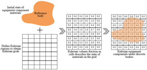
In the study of overheating failures in mechanical equipment, due to the involvement of complex multi-physical field changes, such as fluid flow, heat transfer, and solid thermal expansion, traditional Computational Fluid Dynamics (CFD) finite element methods fall short in addressing these coupling effects. This is especially the case when dealing with significant fluid mesh deformation, where traditional methods might lead to non-convergent computational results, failing to reflect the actual physical phenomena. This situation becomes particularly pronounced in simulating transient temperature fields highly relevant to real-life situations, as it requires the model to accurately simulate temperature changes over time and their impact on the mechanical performance of components. To address these issues, this study employs a combined Eulerian-Lagrangian (CEL) method with thermal-coupling. This method can effectively handle the physical property changes caused by temperature variations, especially the interactions at the fluid-solid interface, thus providing more robust simulation results. The Eulerian approach defines the process of device componentry as shown in Figure 1.
Figure 1. Process of defining device components by Eulerian approach
The basic idea of implementing the analysis method proposed in this paper includes the following key steps: First, establish a fluid-thermal-solid coupled physical model, where the fluid part uses an Eulerian description and the solid part uses a Lagrangian description, ensuring the stability of the solid mesh is not affected by fluid mesh deformation during the simulation. Second, through numerical method improvements, such as time-stepping optimization and iterative solving strategies, to ensure numerical stability during the computation process and enhance the timeliness of the analysis. Lastly, introduce transient temperature field analysis to better handle and interpret the uncertainty and complexity in the data, making this method capable of not only predicting and analyzing overheating failures in mechanical equipment but also providing a scientific basis for fault handling in practical operations.
Choosing transient temperature field for finite element analysis can address the overheating issues faced by mechanical equipment in actual operation, as these issues often involve thermal loads that vary over time. In real-world applications, overheating of mechanical equipment is often not a constant state but varies over time due to changes in external conditions or internal working processes. Transient analysis can simulate and analyze how temperatures change over time and how these temperature changes affect the physical properties of materials and structural integrity. The expression for the relationship between temperature and time in the transient temperature field of mechanical equipment is as follows:
$S=d(a, b, c, s)$ (1)
When analyzing the transient temperature field of mechanical equipment overheating failures, it is first necessary to construct the control equations for the heat transfer process. This typically involves applying the law of energy conservation to derive the heat conduction equation for solids and the convection-conduction equation for fluids. In the solid domain, the heat conduction equation is often expressed as a combination of Fourier's law and energy conservation, while in the fluid domain, the Navier-Stokes equations need to be considered to model the effect of fluid motion on heat transfer. The purpose of constructing these equations is to form a complete mathematical model that can describe the thermal behavior and thermal stress distribution of mechanical equipment under various operating conditions. Assuming the temperature field variable is represented by S, the thermal conductivity coefficients in directions a, b, and c are represented by ja, jb, jc, the material density by ϑ, the heat generation intensity per unit body by W, and the specific heat capacity by zS, the three-dimensional transient heat transfer equation for S is given by the following formula:
$\frac{\partial}{\partial a}\left(j_a \frac{\partial S}{\partial a}\right)+\frac{\partial}{\partial b}\left(j_b \frac{\partial S}{\partial b}\right)+\frac{\partial}{\partial c}\left(j_c \frac{\partial S}{\partial c}\right)+\vartheta W=\vartheta z_S \frac{\partial S}{\partial s}$ (2)
Next, in the stage of setting the heat transfer boundary conditions, the characteristics of the actual working environment of the mechanical equipment must be considered. Depending on different operating conditions and material properties, different types of boundary conditions can be set, such as describing the transient process with the object surface temperature or heat flux as a function of time, or setting thermal convection conditions on the object boundary, where the convective heat transfer coefficient may vary with the fluid's flow characteristics and temperature. These conditions reflect the external environment's impact on the equipment's thermal state, ensuring the model can more accurately predict the temperature distribution in actual operations. The purpose of this step is to allow the numerical model to accurately reflect the thermal interaction between the equipment and its environment, providing appropriate physical boundaries for transient analysis. Assuming the given temperature and heat flux on the surface are represented by S- and w-d, the outward normal cosines on the boundary by va, vb, vc, the heat exchange coefficient by g-z, the shape factor by d, the product of emissivity coefficients of radiating bodies by γ, the Stefan-Boltzmann constant by δ0, and the ambient temperature by S∞. The following formula gives the expression for the given object surface temperature as a function of time variation:
$S(a, b, c, s)=\bar{S}(s)$ (3)
The equation for the given object surface heat flux as a function of time variation is given by the following formula:
$j_a \frac{\partial S}{\partial a} v_a+j b \frac{\partial S}{\partial b} v_b+j_c \frac{\partial S}{\partial c} v_c=\bar{w}_d(s)$ (4)
The expression for thermal convection set on the object boundary is given by the following formula:
$j_a \frac{\partial S}{\partial a} v_a+j_b \frac{\partial S}{\partial b} v_b+j_c \frac{\partial S}{\partial c} v_c=\bar{g}_z\left(S_{\infty}-S\right)$ (5)
The expression for thermal radiation is given by the following formula:
$j_a \frac{\partial S}{\partial a} v_a+j_b \frac{\partial S}{\partial b} v_b+j_c \frac{\partial S}{\partial c} v_c=\gamma d \delta\left(S_{\infty}^4-S^4\right)$ (6)
Finally, in the step of solving the heat transfer process equations, it is necessary to find the minima U of the equations in both spatial and temporal domains. This involves discretizing the continuous problem and iteratively solving the temperature distribution at different time points throughout the entire operating cycle of the equipment. The solving process needs to ensure the stability and convergence of the calculations to obtain a reliable transient temperature field. The key to this step is to transform the mathematical model into a numerical problem that can be iteratively solved using computer algorithms, thereby simulating the complex thermal phenomena occurring in actual overheating failure processes. The following formula gives the initial temperature condition is consistent, the minima U can be calculated using the following formula when the object of study satisfies s=0, S(a,b,c,s)=S-0(a,b,c):
$\underset{S\in _{UZ}^{YZ\left\{ {{Y}_{1}},{{Y}_{2}},{{Y}_{3}} \right\}}}{\mathop{MIN}}\,U=\frac{1}{2}\int{_{\Psi }^{1}\left[ {{j}_{a}}{{\left( \frac{\partial S}{\partial a} \right)}^{2}}+{{j}_{b}}{{\left( \frac{\partial S}{\partial b} \right)}^{2}}+{{j}_{c}}{{\left( \frac{\partial S}{\partial c} \right)}^{2}}-2\left( \vartheta W-\vartheta {{z}_{S}}\frac{\partial S}{\partial s} \right)S \right]d\psi }$ (7)
The functional obtained after coupling the above equation with Eqs. (4)-(6) is given by the following formula:
$\underset{S\in _{UZ}^{YZ\left\{ {{Y}_{1}} \right\}}}{\mathop{MIN}}\,I=\frac{1}{2}\int{_{\Psi }^{1}\left[ {{j}_{a}}{{\left( \frac{\partial S}{\partial a} \right)}^{2}}+{{j}_{b}}{{\left( \frac{\partial S}{\partial b} \right)}^{2}}+{{j}_{c}}{{\left( \frac{\partial S}{\partial c} \right)}^{2}}-2\left( \vartheta W-\vartheta {{z}_{S}}\frac{\partial S}{\partial s} \right)S \right]d\Psi }-\int\limits_{{{Y}_{2}}}^{1}{{{{\bar{w}}}_{d}}SdX+\int\limits_{{{Y}_{3}}}^{1}{{{g}_{z}}}}{{\left( {{S}_{\infty }}-S \right)}^{2}}dX$ (8)
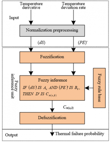
Traditional judgment methods, when dealing with thermal failures of mechanical equipment, usually rely on hard thresholds (such as temperature limits) to determine the occurrence of failures. This approach may not accurately reflect the dynamic changes in equipment thermal state and the trend of failure development in practical applications. The thermal failure of mechanical equipment is often a gradual process, related not only to the current working state but also influenced by usage history, environmental conditions, and other factors. Traditional methods struggle to effectively evaluate the intermediate process of failures and lack the ability to predict future failure risks. Introducing fuzzy theory for thermal failure analysis can quantify uncertainty and partial fuzzy information into thermal failure probabilities. This not only allows for a quantitative description of the degree of thermal failure of components but also enables the prediction and assessment of future thermal failure risks of equipment, providing new ideas and methods for equipment health management and failure prevention. This paper first identifies the key factors affecting the thermal failure of mechanical equipment components and selects temperature derivatives and temperature deviation rates as input variables. Furthermore, it uses Gaussian membership functions to quantify the above input variables into fuzzy logic values. Based on a set fuzzy rule library, these logical language values activate corresponding fuzzy rules for inference. Finally, the centroid method is used to convert fuzzy logic result values into specific numerical values, achieving quantitative analysis of thermal failure of mechanical equipment components. Figure 2 shows the architecture of the fuzzy inference system for mechanical equipment overheating failure states.
Figure 2. Architecture of the fuzzy inference system for mechanical equipment overheating failure states
3.1 Input preprocessing and fuzzification
The temperature derivative reflects the rate of temperature change over time, indicating the speed of temperature rise or fall during equipment operation, which is crucial for capturing the instantaneous changes in thermal state. Meanwhile, the temperature deviation rate describes the deviation between the current working temperature and the component design temperature, which helps to determine whether the equipment is operating within the designed thermal working range. Choosing these two parameters as inputs aims to comprehensively capture the dynamic process and static state of thermal failure, thereby providing accurate input information for thermal failure analysis. Assume the temperatures at moments s and (s-1) are represented by Ss and Ss-1, the component's design temperature by SNO, and the time interval by Δs. The following formula gives the calculation for the two parameters.
$\left\{\begin{array}{l}d S_s=\frac{S_s-S_{s-1}}{\Delta s} \\ P E_s=\frac{S_s-S_{N O}}{S_{o O}}\end{array}\right.$ (9)
These key indicators can provide information on the immediate changes and relative stability of the equipment's thermal state. Since the raw data may contain noise and its distribution might not be suitable for direct fuzzification, input preprocessing is necessary. Assume the allowable minimum and maximum values for component temperature change rate are represented by MIN1 and MAX1, and for component temperature deviation rate by MIN2 and MAX1. The following formula provides the normalization calculation:
$\left\{\begin{array}{l}\left(d S_s\right)^{\prime}=\frac{2}{M A X_1-M I N_1}\left(d S_s-\frac{M A X_1+M I N_1}{2}\right) \\ \left(P E_s\right)^{\prime}=\frac{2}{M A X_1-M I N_1}\left(P E_s-\frac{M A X_1+M I N_1}{2}\right)\end{array}\right.$ (10)
After normalization, fuzzification is required. This step is essential for converting precise numerical values into membership degrees within a fuzzy set, crucial for handling uncertainty and partial truth. This allows the system to deal with various situations between completely true and completely false, thereby better mimicking human reasoning and making complex decisions. Specifically, the preprocessed data is mapped into fuzzy sets through Gaussian membership functions, defining the membership degree of each input value to a fuzzy set. This membership not only reflects the similarity of input values to certain logical language values but also provides a basis for the activation of fuzzy rules, enabling subsequent fuzzy inference to comprehensively assess the thermal failure risk of mechanical equipment based on these fuzzified input values.
3.2 Fuzzy inference
In the analysis of mechanical equipment overheating failures, a single indicator often cannot fully reflect the complexity of the fault, while multi-indicator combined analysis can provide more comprehensive fault characteristic information. Using a dual-input single-output fuzzy inference statement can effectively integrate the two key indicators: the rate of temperature change over time, which reflects the speed of thermal state changes, and the temperature deviation rate, reflecting relative stability, to form a comprehensive judgment of the equipment's thermal state. This helps to address complex overheating phenomena that are difficult to capture with a single data point, enhancing the accuracy of fault diagnosis and the effectiveness of prevention measures. Assuming the logical language values corresponding to (dS)', (PE)', and D' are represented by Au, Bk, and Cm(u,k), respectively, the inference formula for thermal failure probability D' based on normalized (dS)' and (PE)' is:
$\begin{aligned} & \text { IF }(d S)^{\prime} \text { IS } A_u A N D(P E) \text { ' IS } B_k,T H E N D^{\prime} \text { IS } C_{m(u, k)}\end{aligned}$ (11)
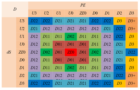
Figure 3. Fuzzy rule table
In the process of analyzing mechanical equipment overheating failures based on fuzzy inference, when generating fuzzy rules, this paper chooses to comprehensively consider the exponential relationship between temperature and failure probability in the Arrhenius model, as well as factors such as thermal damage caused by overheating, such as thermal fatigue fracture. Specifically, based on the thermal damage characteristics and failure data of component materials at different temperatures, an exponential model between temperature and failure probability is established. Then, this model is combined with the rate of temperature change to form input variables for designing fuzzy rules. These rules grade temperature increase and change speed according to fuzzy logic and map these grades to fuzzy sets of failure probability. Figure 3 shows the fuzzy rule table. The input fuzzy sets include: U0~U3 represent four levels of negative direction from small to large. ZE0 is the zero level; D0~D3 represent four levels of positive direction from small to large. The output fuzzy sets include: ZE0 is the zero level; D01, D01~D31, D31 represent eight levels of positive direction from small to large. Assuming the levels of logical language values corresponding to (PE)' and (dS)' are represented by u and k, and the level of logical language value corresponding to D' is represented by CRA(u,k), the model expression is given by:
$C_{R A(u, k)}=\left[\frac{5}{4} \times \sqrt{(u+1)^2+k^2}\right]$ (12)
3.3 Defuzzification
The defuzzification process converts the fuzzy logic results generated by the fuzzy inference framework into precise risk assessment numerical values. For this purpose, the centroid method is used to convert fuzzy logic result values into a specific numerical value, achieving quantitative analysis of thermal failure of mechanical equipment components. Specifically, the output of fuzzy inference is first mapped to a fuzzy set, represented by a membership function indicating different risk levels. Then, the defuzzification method is applied to calculate the representative value of this fuzzy set to determine a specific value between 0 and 1, reflecting the thermal failure risk of the component. This value integrates factors such as the rate of temperature rise and the current temperature's deviation from the design working temperature, providing a quantitative basis for the maintenance decision-making of mechanical equipment. Assuming the logical value obtained from fuzzy inference is represented by Cm(u,k), the symmetry axis of the membership function by Cm(u,k), and the membership value calculated using the Mamdani inference algorithm by MIN(ωu,ωk), with the membership of the fuzzy set corresponding to (dS)' represented by ωu and that corresponding to (PE)' by ωk. The formula for calculating the corresponding thermal failure probability using the centroid method is:
$D=\frac{\sum_{u=1}^V \sum_{k=1}^L C_{m(u, k)}^{\prime} M \mathbb{I}\left(\omega_u, \omega_k\right)}{\sum_{u=1}^V \sum_{k=1}^L M I N\left(\omega_u, \omega_k\right)}$ (13)
3.4 Model validity test
This paper collected temperature deviation rates and temperature change rates of various components of mechanical equipment under different working conditions, as well as recorded corresponding thermal failure incidents, through experiments and historical failure data. By inputting these data into the fuzzy inference model, the model's accuracy in predicting thermal failure probability is verified. A three-dimensional graph visualizing thermal failure probabilities under different temperature deviation rates and change rates was drawn to ensure the model accurately reflects components' thermal state under various temperature conditions. Further, by comparing the thermal failure probabilities output by the model with actual failure data, the model's accuracy and reliability are evaluated, and model parameters or rules are adjusted to improve the model's predictive performance.
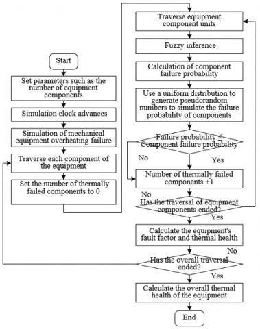
Finally, the thermal state assessment results of each component are integrated to construct an overall thermal state model for the equipment. This paper thoroughly considers the thermal failure probability of individual components and their impact weight on overall machine performance. In this way, component-level risk assessments are elevated to the system level, making the overall equipment thermal failure risk assessment more comprehensive and systematic. Moreover, by continuously monitoring and analyzing the trend of overall thermal state indicators, not only can the health status of equipment be monitored in real time, but preventive measures can also be taken in advance based on model-predicted results, thereby avoiding potential overheating failures and enhancing the reliability and safety of mechanical equipment. Figure 4 presents the mechanical equipment thermal failure state analysis process.
Figure 4. Mechanical equipment thermal failure state analysis process 4 experimental results and analysis
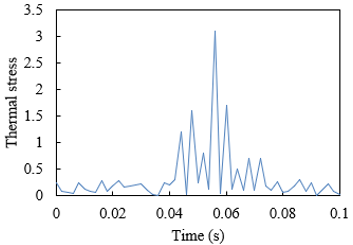
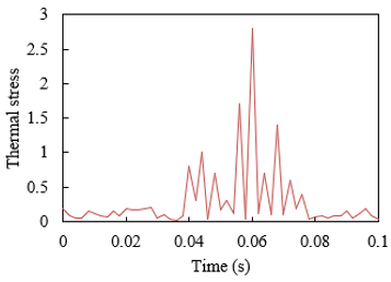
Figure 5 presents the thermal stress-time curves for different mechanical equipment components during thermal failure processes due to wear and thermal expansion. When analyzing the thermal stress-time curves, the focus is on the trend of thermal stress changes over time and the time points when the thermal stress reaches its extreme values. By comparing the peak values and fluctuations of thermal stress in both processes, the impact of wear and thermal expansion on mechanical components can be evaluated. During the wear process, the thermal stress starts at 0.25, then rapidly decreases, reaching a low point at 0.01 seconds, and gradually increases thereafter; during the thermal expansion process, the thermal stress starts at 0.19, with an initial value lower than that in the wear process, then also decreases rapidly and reaches a low point at 0.01 seconds. Looking at the thermal stress-time curves of these two processes, both wear and thermal expansion can cause significant changes in thermal stress of mechanical components to varying degrees, and the peak thermal stress in the wear process is higher than that in the thermal expansion process, indicating that wear has a more significant impact on the component's thermal stress. Significant fluctuations in thermal stress can lead to material fatigue, increasing the risk of component failure. The fluid-thermal-structural coupled model based on transient temperature fields proposed in this paper, by successfully calculating these fluctuations and peak values, has proven its effectiveness in capturing thermal stress changes. Especially in dealing with high thermal stress peaks caused by wear and relatively stable thermal stress changes caused by thermal expansion, the accuracy and stability of the model are particularly crucial. Therefore, the computational method proposed in this paper can be considered effective for predicting and analyzing thermal stress in mechanical equipment during thermal failure processes, providing a powerful computational tool for temperature monitoring and thermal stress analysis of mechanical equipment.
(a) Wear
(b) Thermal expansion
Figure 5. Thermal stress-time curves for different mechanical equipment components during thermal failure processes
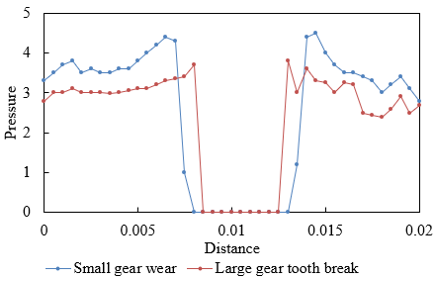
Figure 6 presents the wear contact normal thermal pressure curve for mechanical equipment gear components. As shown in Figure 6, in the initial phase of small gear wear, the thermal pressure starts at 3.3 and rapidly rises to 4.4, indicating that thermal pressure increases sharply at the start of wear. In the middle stage, the thermal pressure drops to 0, corresponding to temporary separation of the small gear contact surface or material removal caused by overheating failure. In the later stages, the thermal pressure rises again to 4.5, then gradually decreases to 2.8, showing a cyclical pattern of recovery and re-increase during the wear process. In the initial phase of large gear tooth breakage, the thermal pressure starts at 2.8 and grows relatively steadily to 3.7, showing a more gradual growth trend. After the tooth breakage occurs, the thermal pressure suddenly drops to 0, due to the loss of gear contact caused by the breakage. In the later stages, the thermal pressure rapidly rises to 3.8, then decreases and stabilizes, fluctuating between 2.5 and 2.9, showing instability and a gradually stabilizing trend after the breakage. It can be concluded that the small gear wear data show dynamic changes during the wear process, including sharp increases, decreases, and recovery. This indicates that gear wear leads to unstable fluctuations in thermal pressure, further causing more complex thermo-mechanical problems. The large gear tooth breakage data show sudden changes in thermal pressure caused by breakage and subsequent instability. The changes in thermal pressure in this case are more dramatic than in wear but eventually stabilize. The fluid-thermal-structural coupled model proposed in the paper accurately predicts these trends in thermal pressure changes, verifying that the method is effective in simulating mechanical equipment overheating failures. Particularly, the model can handle numerical problems caused by large deformations and transient temperature fields, indicating its potential application value in complex thermo-mechanical coupling problems.
Figure 6. Wear contact normal thermal pressure curve for mechanical equipment gear components
Table 1 shows the gear maximum stress and shear conditions under combined thermal failure of mechanical equipment components. It can be seen from the table that Stress 1 has a smaller positive value (55.26) and a larger negative value (121.25), indicating that compressive stress dominates in wear conditions. Stress 2 has a smaller positive value (31.25) and a very large negative value (256.21), further emphasizing the significance of negative stress (compressive stress). Both positive and negative values exist for Shear 1 and Shear 2, but with a significant difference between them, highlighting the importance of force asymmetry under wear conditions. The method proposed in the paper is able to distinguish the significant changes in stress and shear under two different thermal failure conditions of wear and thermal expansion, indicating the model is sensitive to capturing stress distributions under different failure modes. At the same time, the data show the complexity of stress distribution under different failure modes, as the model can precisely calculate these complex stress states, further proving its high accuracy and reliability.
Table 1. Gear maximum stress and shear conditions under combined thermal failure of mechanical equipment components
|
|
Stress 1 |
Stress 2 |
Shear 1 |
Shear 2 |
||||
|
|
Positive |
Negative |
Positive |
Negative |
Positive |
Negative |
Positive |
Negative |
|
Wear |
55.26 |
121.25 |
31.25 |
256.21 |
17.89 |
103.1 |
46.59 |
67.25 |
|
Thermal Expansion |
78.26 |
73.26 |
27.56 |
224.87 |
8.23 |
26.58 |
28.23 |
82.3 |
Table 2. Thermal parameters of common mechanical equipment components
|
Component |
Operating Temperature Range (℃) |
Survival Temperature Range (℃) |
||
|
MinOP |
MaxOP |
MinSU |
MinSU |
|
|
Bearing |
-41 |
74 |
-64 |
149 |
|
Gear |
-28 |
71 |
-54 |
94 |
|
Piston |
-11 |
71 |
-41 |
94 |
|
Crankshaft |
-41 |
81 |
-54 |
94 |
|
Turbine Blade |
-54 |
81 |
-54 |
84 |
|
Heat Exchanger Tubes |
-11 |
71 |
-41 |
94 |
|
Connecting Rod |
0 |
44 |
-31 |
61 |
|
Cylinder Liner |
-24 |
81 |
-35 |
85 |
|
Seal Ring |
11 |
81 |
-79 |
149 |
|
Brake Disc |
0 |
44 |
-21 |
61 |
Table 2 provides the operating and survival capabilities of common mechanical equipment components at different temperature ranges. It can be observed from the table that the operating and survival temperature ranges of different components vary significantly. For example, bearings have a lower maximum operating temperature but a higher maximum survival temperature, meaning bearings can withstand higher temperatures for short periods without damage. Some components, such as connecting rods and brake discs, have lower maximum operating temperatures, indicating they are more sensitive to temperature and overheating can quickly affect their performance. On the other hand, the survival temperature ranges of seal rings and bearings are broader, indicating they can tolerate larger temperature fluctuations. It can be concluded that the fuzzy inference technique used in this paper to analyze overheating failures and effectively handle uncertainty in the model is beneficial for improving the accuracy and reliability of fault diagnosis. This is primarily because fuzzy inference can deal with the uncertainty and ambiguity caused by temperature fluctuations, and through fuzzy logic, the system can better handle the fuzzy states between normal and abnormal, aiding in the earlier identification of potential overheating issues.
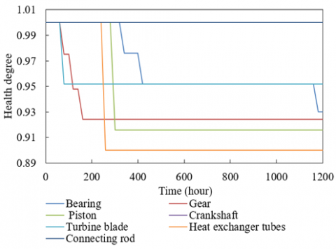
Figure 7. Thermal health of mechanical equipment components
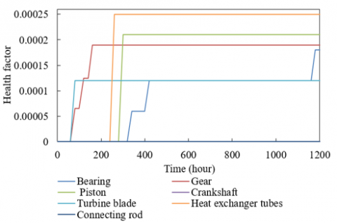
Figure 8. Thermal fault factors of mechanical equipment components
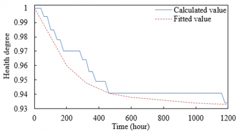
Figure 7 provides thermal health assessment values for a series of mechanical equipment components after operating for different numbers of hours. These values indicate that the health condition of the components changes over time due to wear, aging, or other influencing factors. From the figure, it's observed that the healthiness of bearings, gears, pistons, turbine blades, and heat exchanger tubes decreases over time, while crankshafts and connecting rods remain intact throughout the observation period. Figure 8 records the fault factor measurements of different mechanical equipment components at various operating hours. It's evident that bearings and gears exhibit a slight increase in fault factors after extended operating hours, hinting at potential overheating risks. The fault factors for pistons and heat exchanger tubes start to increase after a certain point, indicating issues with design or materials that require further monitoring and analysis. Although the fault factor for turbine blades increases, the rate of increase is minor, suggesting a more stable response to thermal loads. Since the fault factors for crankshafts and connecting rods remain at zero, it can be inferred that they do not exhibit overheating risks under current operating conditions. Figure 9 showcases the overall thermal health of mechanical equipment. The calculated values eventually stabilize around 0.934 over time, while the fitted values show a consistent downward trend, gradually approaching the calculated values. This implies that the equipment's health condition has stabilized at a lower level.
Figure 9. Overall thermal health of mechanical equipment
Overall speaking, fuzzy inference technology can effectively deal with the uncertainties in actual operations, providing a more accurate and reliable assessment of the thermal health condition of mechanical components. By analyzing actual data, the effectiveness of the model can be verified, offering theoretical foundation and practical guidance for the maintenance and fault prevention of mechanical equipment.
This paper successfully constructed a fluid-thermal-structural coupled model based on transient temperature fields. The model can simulate the thermal behavior of mechanical equipment in actual working environments, including the development of overheating deformation and thermal stress. To overcome the non-convergence issues in traditional numerical calculations for overheating deformation and large deformation meshes, advanced numerical calculation methods were introduced. These methods enhanced the stability and accuracy of the calculations, allowing the model to be effectively used for actual temperature monitoring and thermal stress analysis. Fuzzy inference technology was employed to handle the uncertainty information in the model, improving the accuracy of overheating fault diagnosis. By defining fuzzy sets and rules, fuzzy inference technology can effectively analyze and predict the thermal health condition of mechanical equipment.
Experimental results included thermal stress-time curves, wear contact normal thermal pressure curves, maximum stress and shear condition analyses, and thermal parameter statistics for common mechanical equipment components. These results provide detailed data support for understanding and predicting the behavior of mechanical equipment in terms of thermal faults. The paper evaluated the thermal health of mechanical equipment components after various operating times and measured fault factors at different working hours. These evaluations and measurements provide empirical evidence for assessing the overall thermal health of mechanical equipment.
The research in this paper shows that by establishing a fluid-thermal-structural coupled model and incorporating fuzzy inference technology, it is possible to effectively monitor and predict the thermal health condition of mechanical equipment. The advanced numerical calculation methods solved the issue of numerical non-convergence, ensuring the accuracy and reliability of the model in transient temperature field analysis. The application of fuzzy inference addressed the model's uncertainties, enhancing the precision of fault diagnosis. In-depth analysis of experimental results revealed the impact of wear and thermal expansion on thermal stress and the effect of different operating times on the thermal health of mechanical components. Ultimately, this paper provides scientific methods and data support for the fault prevention and maintenance of mechanical equipment, helping to enhance the stability and lifespan of mechanical equipment, and reducing the economic losses and safety risks associated with overheating failures.
[1] Chou, C., Yan, Z., Zhao, Y., Li, L. (2023). Design of intelligent control system for substation equipment start-up operation tickets. In International Conference on Mechanical, Electronics, and Electrical and Automation Control (METMS 2023), Hangzhou, China, p. 127224D. https://doi.org/10.1117/12.2679385
[2] Yang, L., Wang, Q., Ma, Y., Liu, X. (2023). Research and application practice on technical supervision of nuclear island mechanical equipment in NPP. Journal of Physics: Conference Series, 2468(1): 012170. https://doi.org/10.1088/1742-6596/2468/1/012170
[3] Badea, G., Gagea, A.M., Gagea-Manitiu, V., Iloaie, F.G., Bolboaca, A.M. (2019). Reducing the overheating phenomenon in passive houses by integrating phase change materials. International Multidisciplinary Scientific GeoConference: SGEM, 19(6.3): 491-498. https://doi.org/10.5593/sgem2019V/6.3/S10.063
[4] Bao, Y., Wang, Z., Yang, J., Chen, D., Jing, S., Wu, M., Lu, Q. (2023). A machine olfaction-based overheating diagnosis method for electrical equipment. IEEE Access, 11: 108804-108817. https://doi.org/10.1109/ACCESS.2023.3320714
[5] Liu, P., Xie, T., Jin, S., Zhang, P., Tian, H., Peng, Z. (2023). Simulation analysis of overheating fault mechanism of electrical connection components used in gis/gil sliding contact. Gaodianya Jishu / High Voltage Engineering, 49(5): 2090-2100.
[6] Yang, Y., Zhang, S., Su, K., Fang, R. (2023). Early warning of stator winding overheating fault of water-cooled turbogenerator based on SAE-LSTM and sliding window method. Energy Reports, 9: 199-207. https://doi.org/10.1016/j.egyr.2023.02.076
[7] Chen, Y., Zhang, Q., Gao, J., et al. (2023). Investigation on the dislocation, thermal and mechanical properties, and crystal growth stress of Zr: GdTaO4 scintillator. Optical Materials, 138: 113658. https://doi.org/10.1016/j.optmat.2023.113658
[8] Shen, R., Wang, R., Zhang, J., Fang, Y., Yang, Y., Tian, J. (2023). Modeling and analysis of thermal-mechanical stress in motor insulation. In 2023 26th International Conference on Electrical Machines and Systems (ICEMS), Zhuhai, China, pp. 1508-1513. https://doi.org/10.1109/ICEMS59686.2023.10344454
[9] Shoulders, W.T., Guziewski, M., Swab, J.J. (2024). Microstructural and thermal stress effects on mechanical properties of boron carbide particle-reinforced silicon carbide. Journal of the American Ceramic Society, 107(2): 1249-1261. https://doi.org/10.1111/jace.19535
[10] Gan, C.L., Chung, M.H., Lin, L.F., Huang, C.Y., Takiar, H. (2023). Evolution of epoxy molding compounds and future carbon materials for thermal and mechanical stress management in memory device packaging: A critical review. Journal of Materials Science: Materials in Electronics, 34(30): 2011. https://doi.org/10.1007/s10854-023-11388-5
[11] Huang, D.Y., Ma, Y., Rao, Q.H., Yi, W., Shen, K. (2023). A new semi-analytic method for calculating the thermal-mechanical coupling stress intensity factor of interfacial crack. Theoretical and Applied Fracture Mechanics, 128: 104156. https://doi.org/10.1016/j.tafmec.2023.104156
[12] Bonkile, M.P., Jiang, Y., Kirkaldy, N., Sulzer, V., Timms, R., Wang, H., Offer, G., Wu, B. (2023). Coupled electrochemical-thermal-mechanical stress modelling in composite silicon/graphite lithium-ion battery electrodes. Journal of Energy Storage, 73: 108609. https://doi.org/10.1016/j.est.2023.108609
[13] Wu, H., Sun, J., Peng, W., Jin, L., Zhang, D. (2024). Analysis of flatness and critical crown of hot-rolled strip based on thermal-mechanical coupled residual stress analytical model. Applied Mathematical Modelling, 126: 348-380. https://doi.org/10.1016/j.apm.2023.11.001
[14] Shi, L., Chen, J., Yang, C., Chen, G., Wu, C. (2023). Thermal-fluid-structure coupling analysis of void defect in friction stir welding. International Journal of Mechanical Sciences, 241: 107969. https://doi.org/10.1016/j.ijmecsci.2022.107969
[15] Yuan, J.H., Wang, K., and Gu, X.C. (2023). Dynamic simulation of nozzle structure based on thermal-fluid-solid coupling analysis. Journal of Physics: Conference Series, 2472(1): 012065. https://doi.org/10.1088/1742-6596/2472/1/012065
[16] Wang, Y., Wang, L., Jia, S. (2019). Numerical simulation of air arc impinging to chamber shell with multi-physical coupling method of fluid-thermal-structure. AIP Advances, 9(4): 045316. https://doi.org/10.1063/1.5083940
[17] Han, H., Sun, C., Wu, X., Yang, H., Qiao, J. (2022). Self-organizing interval type-2 fuzzy neural network using information aggregation method. IEEE Transactions on Neural Networks and Learning Systems, 34(9): 6428-6442. https://doi.org/10.1109/TNNLS.2021.3136678
[18] Zhang, R., Xu, K., Zhu, S., Xing, M., Quan, Y. (2022). Modeling of number of sources detection under nonideal conditions based on fuzzy information granulation. IEEE Transactions on Aerospace and Electronic Systems, 59(2): 1749-1757. https://doi.org/10.1109/TAES.2022.3204925
[19] Wang, L., Pei, Z., Qin, K., Yang, L. (2024). Incremental updating fuzzy tolerance rough set approach in intuitionistic fuzzy information systems with fuzzy decision. Applied Soft Computing, 151: 111119. https://doi.org/10.1016/j.asoc.2023.111119