Faeza Mahdi Hadi*![]() | Hasan Shakir Majdi
| Hasan Shakir Majdi![]()
© 2024 The authors. This article is published by IIETA and is licensed under the CC BY 4.0 license (http://creativecommons.org/licenses/by/4.0/).
OPEN ACCESS
The thermal energy transfer characteristics of heat exchangers with thermal fins and evaluates their economic feasibility. It uses computational fluid dynamics simulations and economic analyses to examine various fin geometries, materials, and configurations. The results reveal that fin design parameters, such as height, thickness, spacing, and material properties, significantly influence heat transfer efficiency. The study emphasizes the importance of optimizing these parameters to balance thermal performance and cost-effectiveness. The findings guide engineers and policymakers in selecting and optimizing thermal fins. A range of water flow speeds of 0.1, 0.5, and 1 m/s was used, and the dimensions of the fins were reduced in a manner commensurate with the nature of thermal energy transfer and to reduce the manufacturing cost. The study shows that thermal energy transfer through fins increases with fluid flow speed, with the pipe's exit temperature reaching 88 degrees Celsius at 0.1 m/s and 96 degrees Celsius at 0.5 m/s. The fins' temperature distribution varies, reaching 88 degrees Celsius, 94 degrees Celsius due to fin length changes, and 91 degrees Celsius despite fin size changes. The study also analyzed energy transfer through different shapes and flow speeds, finding that shape 1 transferred 340 W at 1 m/s, shape 2 decreased to 144 W, and shape 3 increased surface area but not volume.
thermal energy transfer, economic performance, thermal fins, heat exchangers, simulation
Heat exchangers are fundamental for productive nuclear power move in enterprises. Warm blades upgrade convective intensity move by expanding surface region. Nonetheless, the ideal setup and monetary ramifications of these improvements are still under research. Factors like blade math, material determination, and dividing altogether impact effectiveness and framework monetary suitability. Mathematical reenactment strategies like computational liquid elements can assist with researching the warm qualities of blade designs. This study expects to overcome any issues between warm designing and monetary examination by assessing blade calculation, material properties, and dividing, and coordinating financial appraisals to decide ideal plan boundaries for ideal warm productivity and practical activity.
The article of Nemati et al. [1] centers around streamlining the state of annular balances in a multi-column air heat exchanger to further develop execution without causing producing costs. The review utilizes a consistent state fierce CFD model to foresee air-side intensity move, pressure drop, and entropy age in a four-line heat exchanger. The blade shapes are then enhanced exclusively, bringing about a non-homogenous custom heap of cylinders. The outcomes show that curved annular-molded blades limit pressure drop and entropy age, while roundabout formed balances at the entry district amplify heat move. The entropy age rate is likewise decreased, showing a thermodynamic improvement in tube pack execution. Shadlaghani et al. [2] explored the effect of inward serrated balances and whimsy on normal convection heat move between annular spaces with roundabout, square, and three-sided cross areas. The outcomes show that blades increment all out heat move, with the best rate being accomplished when balances are mounted on the internal mass of a converse three-sided annulus. The investigation likewise discovered that capricious annuli showed preferred heat move rates over concentric ones. Stage Change Materials (PCMs) are progressively utilized in energy capacity because of their unfortunate warm conductivity [3]. This paper presents a PCM-blade structure improvement system utilizing the Layered Warm Opposition (LTR) model in 2D tube shaped math. The model lessens computational expenses and enhances finned heat pipe structures, uncovering that more slender blades lead to bring down framework costs and a thickness limit for balance welding. The model additionally gives ideal material utilization expenses to huge scope dormant nuclear power stockpiling frameworks.
Utilized a molecule swarm improvement way to deal with decide the ideal miniature blade math for twofold line heat exchangers [4]. The factors incorporate miniature blade number, level, and helix point. The review considers Reynolds number and cylinder breadth. Mathematical conditions are addressed utilizing ANSYS CFX v.15. Results show that ideal miniature balance level increments with Reynolds number, however inverse patterns for helix point. Ahmed [5] proposed a creative warm plan for plate-blade heat sinks (PFHS) by embedding ribs between directs in various sizes, positions, numbers, and directions. The review intends to explore the impact of ribs on PFHS while keeping the quantity of blades steady and at the same time diminishing the quantity of balances. Results show that ribbed plate-blade heat sinks (RPFHS) give 1.55 times more prominent warm execution than PFHS under comparing conditions, yet this improvement lessens with expanding ribs. Cryogenic cycles include air division and liquefaction, requiring minimized and productive gear for liquid intensity move [6]. Multistream plate-blade heat exchangers are an answer, with concentrates on zeroing in on heat move computation, surface examination, stream obstruction, and plan improvement. In any case, no generally acknowledged approach exists for layer design plan. This article audits conventional plan draws near, examines new strategies, canny heuristic calculations, and the "layer design ring model" and "double goal capability" streamlining techniques.
Computational liquid elements (CFD) were utilized to recreate a three-layered concentric high temperature heat exchanger, utilizing helium gas and liquid salt as hot and cold streams [7]. The intensity exchanger's ideal presentation was accomplished by streamlining boundaries like channel width, blade length, pitch, thickness, and point. The Taguchi strategy diminished CFD reproductions, bringing about ideal setups with channel width of 1 mm, blade length of 11 mm, and balance thickness of 1.125 mm. Iqbal et al. [8] examined the ideal plan of longitudinal blades expanded to the external surface of a twofold line for boosting the form heat move coefficient. The plan is affected by attributes like length, blade number, material conductivity, and control focuses. The outcomes show that ideal plans with identical distance across and pressure driven measurement further develop heat move coefficients by up to 289% and 70% individually. The best plans, in view of identical width (Q=500), give up to 39% higher intensity move coefficients. Iqbal et al. [9] examined the ideal state of longitudinal balances expanded to the external surface of an internal line encased inside a concentric external line to boost the Nusselt number in a consistent laminar and completely created stream. The wall-balance gathering is made of exceptionally conductive material and exposed to uniform intensity transition limit conditions. The ideal profile is reliant upon the quantity of balances, radii proportion, control focuses, and trademark length. The ideal blade shape is normally three-sided on more modest inward lines and wavy on bigger ones. Iqbal et al. [10] centers around improving finned twofold lines with three-sided blades for laminar constrained convection under consistent intensity motion limit conditions. The objective is to find ideal designs that boost the Nusselt number. The review utilizes a hereditary calculation and limited component strategy to track down ideal designs, assessing their presentation and contrasting them and trapezoidal balances. The outcomes are approved and precise when contrasted with existing writing.
Kim et al. [11] proposed shut structure relationships for warm advancement of vertical plate-blade heat sinks under normal convection. Scientific arrangements are introduced for high channel perspective proportions, conductivity proportions, and low Rayleigh numbers. Trial and mathematical examinations approve the insightful arrangements. The ideal blade thickness relies upon level, strong conductivity, and liquid conductivity, free of Rayleigh number, consistency, and intensity sink length. Kim et al. [12] examined warm streamlining of a plate-balance heat sink utilizing volume-averaging hypothesis (Tank). Results show that rising blade thickness in the upward course lessens warm obstruction by up to 20%, with the decrease expanding with siphoning power. Kundu [13] presented an iterative plan for deciding the genuine tip temperature and nearby blade surface temperature in wet balances. It presents the annular step blade (ASF) for more powerful usage of balance material contrasted with the annular plate blade. The adjusted warm investigation of completely wet balances and somewhat wet blades was utilized for enhancement. The outcomes showed a huge contrast in results contrasted with distributed results, and the greatest intensity move rate per unit volume for ASF was dependably higher than that of the annular circle balance for a similar plan condition. Two new balance calculations, FQCT and FCAT, are proposed for further developing intensity move rate per unit volume in level plate blades [14]. These blades outline a roundabout cylinder with a quarter roundabout cut at the tip and a round bend to cut at the tip. The warm presentation of these blades was resolved utilizing a semianalytical technique, and the review showed the way that FQCT and FCAT can disperse more intensity than FCT, particularly when space requirements exist. Kundu and Das [15] examined the exhibition of elliptic plate blades utilizing a semi-logical strategy, uncovering that proficiency can be anticipated utilizing the area technique. Be that as it may, the annulus technique isn't reasonable for this blade math. The review proposes a strategy for ideal balance plan.
Kundu and Das [16] presented a semi-logical strategy for tackling the intensity conduction condition in an offbeat annular plate blade, taking into account convective and protected conditions. It thinks about the exhibition of concentric and whimsical blades with a similar sweep proportion. The ideal aspects for offbeat annular balances are resolved utilizing Lagrange multiplier strategy, with space limitation considering more modest volumes. Yu and Chen [17] talks about the advancement of rectangular profile round balances with variable warm conductivity and convective intensity move coefficients. The nonlinear leading convecting-emanating heat move condition is addressed utilizing the differential change technique. The ideal blade length is practically autonomous of balance base temperature for unadulterated convection, yet more limited for higher temperatures. Reda and Majdi [18] examined two even cross-stream pipes with three release rates for boiling water, contrasting them with decide the ideal Nusselt number. The primary kind, without added substances, accomplished the ideal pace of 1.5 liters each moment. The subsequent sort, with right-point turbulators, further developed the Nusselt number by 28.1%, contrasted with the commonplace circumstance without points. Majel and Kamal Hasan [19] looked at violent stream around a cylinder utilizing multi-states of winglet vortex generators at various approaches. It researches the impact of winglet on heat move and tension drop of blade and cylinder heat exchangers in rectangular channels with Reynolds numbers going from (19000) to (49000). The discoveries show that the structure and approach of winglets influence heat move coefficient and contact factor. The ideal arrangement for additional creating power move is the rectangular sort, with the three-sided type making the least force move.
The petrochemical industry is specializing in decreasing power intake in refinery operations due to rising energy fees and environmental concerns [20]. A observe using monitored plant data from Nigeria's Niger Delta refinery located that disposing of cross-pinch heat exchangers changed into the first-class retrofit design, ensuing in giant energy performance improvements, reduced working costs, and elevated warmth transfer vicinity. This design is usually recommended after additional value attention. The proposed Pinch and Mathematical Programming Methodology integrates reactor and Threshold Heat Exchanger Network (HEN) for optimization [21]. It analyzes electricity intake, application intake, conversion, and reactor temperature. A Mixed Integer Nonlinear Programming model is developed, figuring out most internet annual revenue and application consumptions. The method objectives most desirable conversion and parameters, resulting in a 27.82% increase in net annual sales after steam-reforming. A low-cost, person-friendly scheme for pinch design using MATLAB is proposed for actual-scale commercial issues [22]. Tested for accuracy and robustness, it determines hot, bloodless, cooling, and heating loads using the temperature c programming language approach. The proposed solutions are replicate snap shots of rigorous approaches.
The field of liquid mechanics known as computational liquid elements (CFD) utilizes mathematical strategies and calculations to mimic and look at the way of behaving of liquids, including gases and fluids, in various actual frameworks. It has developed into a significant instrument for exploring and gauging liquid stream peculiarities in the fields of designing, physical science, and different sciences. Crucial ideas of liquid elements, for example, the Navier-Stirs up conditions that make sense of the protection of mass, energy, and energy in liquid streams, are at the groundwork of computational liquid elements (CFD). To gauge the liquid's conduct after some time and space, CFD recreations break down complex liquid stream issues into discrete computational parts, for example, cells or network focuses, and afterward address these conditions iteratively.
In the momentum study, water is considered as the running liquid in the framework, the attributes of stream are thought to be the consistent stream, three layered, Newtonian, incompressible and Violent.
2.1 Governing equations
2.1.1 Standard k-є model
The following transport equations are used to determine the kinetic energy of the turbulence, k, and its rate of dissipation:
$\frac{\partial }{\partial t}\left( \rho k \right)+\frac{\partial }{\partial {{x}_{i}}}\left( \rho k{{u}_{i}} \right)=\frac{\partial }{\partial {{x}_{j}}}\left[ \left( \mu +\frac{{{\mu }_{t}}}{{{\sigma }_{k}}} \right)\frac{\partial k}{\partial {{x}_{j}}} \right]+{{G}_{k}}+{{G}_{b}}-\rho \varepsilon -{{Y}_{M}}+{{S}_{k}}$ (1)
and
$\frac{\partial }{\partial t}\left( \rho \varepsilon \right)+\frac{\partial }{\partial {{x}_{i}}}\left( \rho \varepsilon {{u}_{i}} \right)=\frac{\partial }{\partial {{x}_{j}}}\left[ \left( \mu +\frac{{{\mu }_{c}}}{{{\sigma }_{z}}} \right)\frac{\partial \varepsilon }{\partial {{x}_{j}}} \right]+{{C}_{1z}}\frac{\varepsilon }{k}\left( {{G}_{k}}+{{C}_{3c}}{{C}_{b}} \right)-{{C}_{2z}}\rho \frac{{{\varepsilon }^{2}}}{k}+{{S}_{s}}$ (2)
Gk, which is determined in accordance with the instructions in Modeling Turbulent Production in the k-e Models, denotes the creation of turbulence kinetic energy resulting from mean velocity gradients. Effects of Buoyancy on Turbulence in the k-e Models describes how to compute Gb, which is the kinetic energy generated by buoyancy that causes turbulence. As computed in Effects of Compressibility on Turbulence in the k-e Models, YM represents the variable dilatation in compressible turbulence's contribution to the total dissipation rate. Constants include C1r, C2r and C32. The turbulent Prandtl numbers for k and ${{\varepsilon }_{r}}$ are ${{\sigma }_{\varepsilon }}$ and$~{{\sigma }_{k}}$, respectively. User-defined source terms ${{S}_{k}}$ and ${{S}_{z}}$ are used.
Combining k and, the turbulent (or eddy) viscosity, ${{\mu }_{t}}$ is calculated as follows:
${{\mu }_{t}}=\rho {{C}_{\mu }}\frac{{{k}^{2}}}{\varepsilon }$ (3)
where, ${{C}_{\mu }}$ is a constant. The model constants ${{C}_{1\varepsilon }},{{C}_{2\varepsilon }},{{C}_{\mu }},{{\sigma }_{k}}$, and ${{\sigma }_{\varepsilon }}$ have the following default values:
${{C}_{1x}}=1.44,{{C}_{2r}}=1.92,{{C}_{\mu }}=0.09,{{\sigma }_{k}}=1.0,{{\sigma }_{z}}=1.3$
These default values were established by studies on fundamental turbulent flows, including boundary layers, mixing layers, and jets—shear flows that are regularly encountered—as well as on decaying isotropic grid turbulence. They have been discovered to function rather well for a variety of free and wall-bounded shear flows. Although the model constants' default values are the established industry standards, you can alter them (if necessary) in the Viscous Model Dialog Box.
2.1.2 Mass equation
The commitment to the mass hotspot for ease p in a cell is
${{m}_{p}}=-{{m}_{p{q}'}}$ (4)
and for phase $q$ is:
${{m}_{q}}={{m}_{{p}'{q}'}}$ (5)
2.1.3 Momentum equation
There is no energy source. For the Eulerian model, the energy source in a cell for stage p is [1]:
${{m}_{p}}{{\vec{u}}_{p}}=-{{m}_{piq}}{{\vec{u}}_{p}}$ (6)
and for phase $q$ is:
${{m}_{q}}{{\vec{u}}_{q}}={{m}_{pqq}}{{\vec{u}}_{p}}$ (7)
2.1.4 Energy equation
For every single multiphase model, the accompanying energy sources are added. The energy source in a cell for stage p is:
${{H}_{p}}=-{{m}_{{{p}^{i}}{{q}^{i}}}}\left( h_{q}^{{{f}^{i}}}-h_{p}^{{{f}^{k}}} \right)$ (8)
and for phase $q$ is:
${{H}_{q}}={{m}_{{{p}^{i}}{q}'}}\left( h_{q}^{{{f}^{j}}}-h_{p}^{{{f}^{i}}} \right)$ (9)
where, $h_{p}^{{{f}^{i}}}$ and $h_{q}^{{{f}^{j}}}$are the arrangement enthalpies of species $i$ of stage p and species j of stage q, separately. The distinction between $h_{p}^{{{f}'}}$ and $h_{q}^{{{f}^{j}}}$ is the dormant intensity.
2.2 System geometry
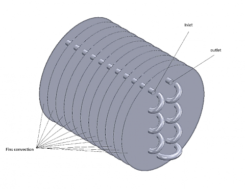
The models were designed using the SolidWork program, version 2022, SolidWorks is a 3D computer-aided design (CAD) software used for creating models and designs for mechanical, electrical, and architectural engineering projects. It allows designers and engineers to create detailed 3D models, simulate movement and performance, and generate technical documentation for production. SolidWorks is widely used in industries such as aerospace, automotive, defense, and manufacturing. Its features include sketching, 3D modeling, assembly design, sheet metal design, and rendering. The fins were designed with a diameter of 200 mm and a thickness of 0.5 mm, and then a tube with a diameter of 9.53 mm and a length of 2200 mm, twisting back and forth to obtain the best heat transfer to the fins, as shown in Figure 1.
Figure 1. Design geometry
2.3 Mesh generation
Generally, unstructured matrices are effective for complex calculations, so for the above reason, the unstructured tetrahedron frameworks was utilized in the ongoing review.
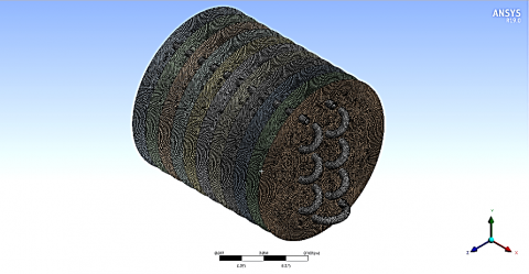
With just one phase from the user, ANSYS can generate solid geometry meshes and three-dimensional models. In this investigation, there were cells extracted from a total of (1383929) tetrahedron element, and sizing of element 1mm see Figure 2.
Figure 2. Mesh generated
An accurate mesh must be created in order to solve the equations because the simulation process depends on complicated algorithms to work on the matrices present in the domain. After that, use the mesh's dependability to find a remedy and bring the outcomes to a stable condition. It is important to create more than one mesh and more than one mesh dependability due to the variety of models that have been simulated. The value of the element was 1383929 when the total heat transfer reached 339.3 W as in Table 1.
Table 1. Mesh independency
|
Case |
Element |
Node |
Total Heat Transfer (W) |
|
1 |
725469 |
512319 |
349.6 |
|
2 |
1125660 |
724528 |
341.7 |
|
3 |
1206789 |
956654 |
339.9 |
|
4 |
1383929 |
1174637 |
339.3 |
2.4 Conditions of the boundary
A range of water flow speeds of 0.1, 0.5, and 1 m/s was used, and the dimensions of the fins were reduced in a manner commensurate with the nature of thermal energy transfer and to reduce the manufacturing cost, as in Figure 3.
Figure 3. Boundary conditions
Pinch Analysis is a method employed by process engineers inter alia to enhance the layout and run of heat exchange networks. It plays an effective role in the terms of reduction of the energy use while and costs are cut down and efficiency of processes is enhanced. The gist is gathering the process data, defining the problem statement, creating a heat exchanger network, determining the pinch points, conducting analytical simulations, implementing numerical simulation software, collecting the results and make a sensitivity analysis, optimizing the network, implementing the suggested changes, and later monitoring and maintaining the network. Our objective lies on getting the most energy efficiency, operating at a cost-friendly side, and a feasible manner. The methodology is not only composed of sensitivity analysis, but also it is used in order to estimate the influence of deviations in process parameters, on the effectiveness of the network. The process of implementing the given changes in the factories process is the vital part if the factory is to be efficient and reliable.
In this paragraph, we will review all the results obtained through the simulation program regarding the temperatures transferred and the cooling process of the fins, as well as the amount of heat transferred through the fins.
(a)
(b)
(c)
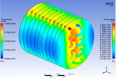
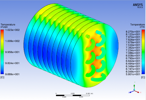
Figure 4. Temperature contour of fully volume fins at different velocity. (a) 0.1 m/s, (b) 0.5 m/s, (c) 1 m/s
3.1 Effect of fluid velocity
The velocity of liquid in a cylinder with blades fundamentally impacts the temperature conveyance. It influences heat move rates, limit layer improvement, disturbance and blending, temperature angles, and consistency of temperature form. Higher liquid speeds improve the convective intensity move coefficient, prompting lower temperatures. The thickness and qualities of the limit layer likewise assume a part. Choppiness can advance better blending and uniform temperature conveyance, while temperature slopes can be more extreme in specific locales. Upgrading liquid speed is pivotal for accomplishing wanted warm execution and successful cooling or warming in applications including finned tubes.
From Figure 4, which shows the transfer of temperatures through the fins at different fluid flow speeds, it is noted that the increase in the fluid flow speed increases the transfer of thermal energy through the fins through temperatures. At a flow speed of 0.1 m/s, the exit temperature of the pipe reached 88 degrees Celsius, while at speed 0.5 m/s it was 96 degrees Celsius, while at speed 1 it reached 97 degrees Celsius. This gives a clear understanding of the transfer of thermal energy during slow speeds.
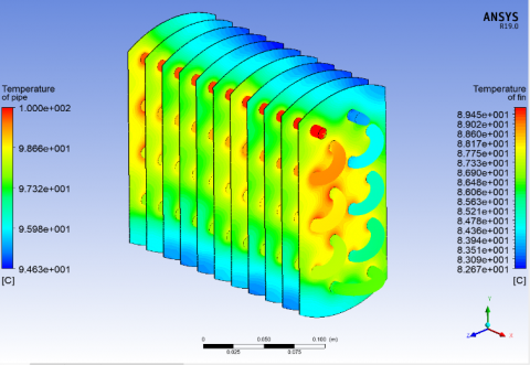
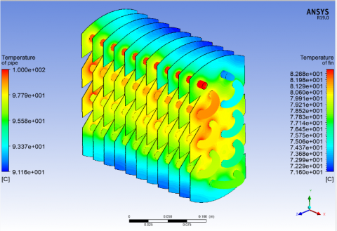
3.2 Effect of the length of fins
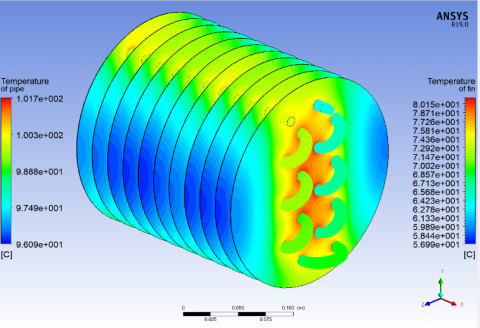
The length of balances in a cylinder containing blades is a vital plan boundary that influences the temperature form inside the framework. Longer balances give a more noteworthy surface region to warm exchange, upgrading the intensity move rate and considering more effective cooling or warming. They additionally influence heat conduction along the blades, prompting varieties in temperature along the balance surfaces. The length of blades likewise influences temperature dispersion, with locales with longer balances showing more uniform temperature appropriations. The ideal blade length relies upon the particular application, wanted warm execution, and other plan contemplations. In addition, the length acquaints extra warm obstruction with heat move. Legitimate balance length choice is fundamental for accomplishing wanted temperature profiles and streamlining warm execution.
From Figure 5, which shows the temperatures distributed in the fins, it is evident in the first figure that the amount of heat in the tube exit area reached 88 degrees Celsius, or in the second figure, it rose to 94 degrees Celsius due to the decrease in the length of the fin. Moreover, in the third figure despite the decrease in the size of the fins. It gained a larger surface area for thermal discharge, and thus the temperature reached 91 degrees Celsius.
3.3 Total heat transfer
Liquid speed in a cylinder with balances essentially influences the exchange of nuclear power between the liquid and blades. The convective intensity move coefficient (h) is affected by liquid speed, which can be expanded to further develop heat move. The thickness of the limit layer on balance surfaces additionally relies upon liquid speed. Choppiness, a consequence of higher liquid speeds, can improve heat move by lessening protection from heat stream. The dissemination of the convective intensity move coefficient along the cylinder's length can likewise be affected by liquid speed. Nonetheless, expanding liquid speed can bring about higher strain drop, which can influence siphoning power and tension drop. Thusly, a compromise between boosting heat moves and limiting tension drop is fundamental.
The analysis points to the concept of life cycle cost analysis (LCCA) which provides the total ultimate cost of ownership during the due product lifespan inclusive of the initial capital expenditure, operating costs, maintenance expense, and end of life arrangements. Comparison of designs will be undergone in the next work, which starts from the economic aspect of each design, to the sensitivity analysis, risk assessment, and decision aid tools. The analysis needs to be based on criteria including the maximum initial investment required, updated operational costs, and design of the system, which may affect its ability to perform optimally and sustainably. The report discovery can help the stakeholders to develop evidence-based arguments and the overall decision-making process for heat exchanger recovery systems.
(a)
(b)
(c)
Figure 5. Temperature contour of velocity 0.1 m/s at different shape. (a) Shape 1, (b) Shape 2, (c) Shape 3
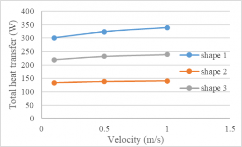
Figure 6 shows the amount of energy transferred through the group of shapes and with different flow speeds. It can be seen from shape 1 that the amount of heat transferred reached 340 W at a speed of 1 m/s. In the second shape, it decreased to 144 W due to a decrease in the size of the fins. As for the third shape, it decreased. It reached 240 W, and this indicates an increase in the surface area and a reduction in the amount of fins in terms of the financial cost of manufacturing.
Figure 6. Total heat transfer of shapes
From Table 2, it is clear that the decrease in volume does not indicate a decrease in the surface area for transfer. Here lies the benefit of SHAPE 3, as it indicates a reduction in size, which is in favor of the financial cost, and at the same time obtains a higher surface area for transfer, and thus the amount of heat transfer reached 218 W. A paper that has looked in to the geometry of fins for heat exchangers show different shapes, for example - rectangle, triangle, a trapezium, the so-called helical, pins and wavy fins. The shape chooses to use decides thermal transfer efficiency and possibly manufacturing cost too. Rectangular fins holding traction in terms of simplicity in the design and manufacturing department are commonly used. Tricontave fins, however, are easier to produce and create less resistance to fluid flow, thus leading to easy and comfortable movement of the prosthetic limb. Simplicity and the better flow of Q are provided by the Hexagonal fins. By using spiral fins more effective heat transfer is ensured but at the cost of increased cost in manufacturing them. Pin fins provide the highest surface area density per unit of fin volume but may be difficult to manufacture compared with other kinds of fins. Fin profile may be sinusoidal or wavy, this geometric effect has the capacity to create much higher surface area, hence heat transfer efficiency is potentially enhanced. The result suggests that there is an advantage in choosing different designs for the heat exchanger.
Table 2. Total heat transfer with volume and area
|
Shape |
Total Heat Transfer (W) |
Volume (cm3) |
Area (m2) |
Cost ($) |
|
1 |
301.12 |
166.00 |
0.67 |
36.88 |
|
2 |
132.97 |
99.00 |
0.20 |
21.99 |
|
3 |
218.68 |
94.00 |
0.38 |
20.88 |
The Pinch Analysis is one of the approaches developed to obtain what total heat transfer takes place in a heat-exchange network. It consists in using simulators which are using numerical and analytical techniques to model the network and control process limits to be met. Finally, the value for the entire heat transfer is computed by adding together the heat transferred in each of the heat exchangers. The reconciliation yields a trial balance; hence checks are made to confirm that its evidence is accurate. Optimization is among the ways used to tighten the network and ensure that heat recovery is optimum and is offered under any process limits. The effectiveness of the improved heat exchanger network is assessed by measuring the total heat transfer, taking into account metrics like energy efficiency, affordability, and running a system long term.
The results are summarized as follows:
1. The study demonstrates that the transfer of thermal energy through fins increases with fluid flow speed. At 0.1 m/s, the pipe's exit temperature reached 88 degrees Celsius, while at 0.5 m/s it reached 96 degrees Celsius. The fins' temperature distribution also varies, with heat reaching 88 degrees Celsius, 94 degrees Celsius due to fin length changes, and 91 degrees Celsius despite fin size changes.
2. The study analyzed energy transfer through various shapes and flow speeds. Shape 1 transferred 340 W at 1 m/s, while shape 2 decreased to 144 W due to fin size reduction. Shape 3 increased surface area and fin size, but not volume. SHAPE 3 reduced fin size, reducing cost but achieving a higher surface area, resulting in 218 W heat transfer.
3. The results show that the heat transfer through the pipes is increased by the speed of fluid van flows and that more heat is absorbed at the end of the pipe: 88 degrees Celsius at (0.1 m/s), 96 degrees Celsius at (0.5 m/s) and 97 degrees Celsius at a speed of (1 m/s). Through the third fin at the heat distribution is visible three figures with the first figure showing 88 degrees Celsius, the second figure 94 degree Celsius, and figure three only 91 degree Celsius is visible. The heat transmission amount varies through different shapes and flow speeds, the first shape at 1m/s giving off 1340 W, the second shape 360 W, and the third shape at 2 m/s 240 W.
Recommendation:
1. Use larger heat exchanger dimensions to simulate the pinch process.
2. Conduct experimental analyzes to reach results close to the numerical aspect.
3. Working on new algorithms to obtain better comparative results to balance thermal performance and cost-effectiveness, including but not limited to particle swarm optimization, genetic algorithms.
[1] Nemati, H., Moghimi, M.A., Sapin, P., Markides, C.N. (2020). Shape optimisation of air-cooled finned-tube heat exchangers. International Journal of Thermal Sciences, 150: 106233. https://doi.org/10.1016/j.ijthermalsci.2019.106233
[2] Shadlaghani, A., Farzaneh, M., Shahabadi, M., Tavakoli, M.R., Safaei, M.R., Mazinani, I. (2019). Numerical investigation of serrated fins on natural convection from concentric and eccentric annuli with different cross sections. Journal of Thermal Analysis and Calorimetry, 135: 1429-1442. https://doi.org/10.1007/s10973-018-7542-y
[3] Pan, C., Vermaak, N., Romero, C., Neti, S., Hoenig, S., Chen, C.H. (2017). Efficient optimization of a longitudinal finned heat pipe structure for a latent thermal energy storage system. Energy Conversion and Management, 153: 93-105. https://doi.org/10.1016/j.enconman.2017.09.064
[4] Dastmalchi, M., Sheikhzadeh, G.A., Arefmanesh, A. (2017). Optimization of micro-finned tubes in double pipe heat exchangers using particle swarm algorithm. Applied Thermal Engineering, 119: 1-9. https://doi.org/10.1016/j.applthermaleng.2017.03.025
[5] Ahmed, H.E. (2016). Optimization of thermal design of ribbed flat-plate fin heat sink. Applied Thermal Engineering, 102: 1422-1432. https://doi.org/10.1016/j.applthermaleng.2016.03.119
[6] Wang, Z., Lim Y. (2016). Layer pattern thermal design and optimization for multistream plate-fin heat exchangers - A review. Renewable and Sustainable Energy Reviews, 53: 500-514. https://doi.org/10.1016/j.rser.2015.09.003
[7] Hung, T.C., Chen, H.C., Lee, D.S., Fu, H.H., Chen, Y.T., Yu, G.P. (2015). Optimal design of a concentric heat exchanger for high-temperature systems using CFD simulations. Applied Thermal Engineering, 75: 700-708. https://doi.org/10.1016/j.applthermaleng.2014.09.079
[8] Iqbal, Z., Syed, K.S., Ishaq, M. (2015). Fin design for conjugate heat transfer optimization in double pipe. International Journal of Thermal Sciences, 94: 242-258. https://doi.org/10.1016/j.ijthermalsci.2015.03.011
[9] Iqbal, Z., Syed, K.S., Ishaq, M. (2013). Optimal fin shape in finned double pipe with fully developed laminar flow. Applied Thermal Engineering, 51(1-2): 1202-1223. https://doi.org/10.1016/j.applthermaleng.2012.10.036
[10] Iqbal, Z., Ishaq, M., Syed, K.S. (2012). Optimization of laminar convection on the shell-side of double pipe with triangular fins. Arabian Journal for Science and Engineering, 39: 2307-2321. https://doi.org/10.1007/s13369-013-0751-6
[11] Kim, T.H., Do, K.H., Kim, D.K. (2011). Closed form correlations for thermal optimization of plate-fin heat sinks under natural convection. International Journal of Heat and Mass Transfer, 54(5-6): 1210-1216. https://doi.org/10.1016/j.ijheatmasstransfer.2010.10.032
[12] Kim, D.K., Jung, J., Kim, S.J. (2010). Thermal optimization of plate-fin heat sinks with variable fin thickness. In 2010 14th International Heat Transfer Conference, Washington, DC, USA, pp. 517-522. https://doi.org/10.1115/IHTC14-22728
[13] Kundu, B. (2009). Analysis of thermal performance and optimization of concentric circular fins under dehumidifying conditions. International Journal of Heat and Mass Transfer, 52(11-12): 2646-2659. https://doi.org/10.1016/j.ijheatmasstransfer.2008.12.017
[14] Kundu, B. (2007). Performance and optimization of flat plate fins of different geometry on a round tube: A comparative investigation. Journal of Heat and Mass Transfer, 129(7): 917-926. https://doi.org/10.1115/1.2717255
[15] Kundu, B., Das, P.K. (2007). Performance analysis and optimization of elliptic fins circumscribing a circular tube. International Journal of Heat and Mass Transfer, 50(1-2): 173-180. https://doi.org/10.1016/j.ijheatmasstransfer.2006.06.043
[16] Kundu, B., Das, P.K. (1999). Performance analysis and optimization of eccentric annular disk fins. Journal of Heat and Mass Transfer, 121(1): 128-135. https://doi.org/10.1115/1.2825925
[17] Yu, L.T., Chen, C.K. (1999). Optimization of circular fins with variable thermal parameters. Journal of the Franklin Institute, 336(1): 77-95. https://doi.org/10.1016/s0016-0032(97)00021-5
[18] Reda, S., Majdi, H. (2023). Evaluation of double pipe heat exchanger performance with right angle turbulator. Al-Rafidain Journal of Engineering Sciences, 1(1): 58-65. https://doi.org/10.61268/91tf8086
[19] Majel, B.M., Kamal Hasan, W. (2023). Heat transfer augmentation in fin and tube heat exchanger embedded with vortex generators. Al-Rafidain Journal of Engineering Sciences, 1(1): 42-50. https://doi.org/10.61268/qk2k0g77
[20] Yee, T.F., Grossmann, I.E. (1990). Simultaneous optimization models for heat integration—II. Heat exchanger network synthesis. Computers & Chemical Engineering, 14(10): 1165-1184. https://doi.org/10.1016/0098-1354(90)85010-8
[21] Zhang, D., Lv, D.H., Yin, C.F., Liu, G.L. (2020). Combined pinch and mathematical programming method for coupling integration of reactor and threshold heat exchanger network. Energy, 205: 118070, https://doi.org/10.1016/j.energy.2020.118070
[22] Tewari, K., Agrawal, S., Arya, R.K. (2015). Generalized pinch analysis scheme using MATLAB. Chemical Engineering & Technology, 38(3): 530-536. https://doi.org/10.1002/ceat.201400475