Khawla Dib![]() | Youcef Zennir*
| Youcef Zennir*![]() | Hichem Bounezour
| Hichem Bounezour![]() | Seif El Islam Bouasla
| Seif El Islam Bouasla![]()
© 2024 The authors. This article is published by IIETA and is licensed under the CC BY 4.0 license (http://creativecommons.org/licenses/by/4.0/).
OPEN ACCESS
Reformer heater tubes operate in a complex environment involving high temperatures, pressure, and corrosive atmospheres. Depending on the operating conditions, several mechanisms can occur, such as creep, oxidation, high-temperature hydrogen attack, and carburization. This paper aims to evaluate the degradation degree of catalytic reformer heater tubes made of ferritic alloy-steel A 335 grade P22 based on a combination of inspection techniques, including visual inspection, microstructure observation, metallographic analysis, and mechanical properties testing. The results show severe oxidation and scaling occurring on the outer surface of the heater tube due to operating the tubes above recommended levels. Several recommendations are suggested to reduce the risk of thermal oxidation and prevent similar damages from reoccurring in the future.
damage, failure, heater tubes, ferritic alloy-steel, oxidation, preventive maintenance
Reformer heaters are widely used in the petroleum and petrochemical industries to obtain reformate used for blending. Radiant tubes are the most critical components of a reformer heater that operate under high temperatures and pressure for extended periods [1]. Tubes can experience deterioration both internally and externally. Several damage mechanisms can occur in catalytic reformer heater tubes, such as creep, external oxidation, and high temperature hydrogen attack (HTHA), carburization, and metal dusting, caused by abnormal operation, low flow, high temperature, or flame impingement, which may lead to a reduction in its structural integrity and eventual damage that might cause fire when loss of containment occurs [2-5].
A leak or failure in a piping system can range from a minor inconvenience for low-consequence fluids to a potential source of a process safety incident for higher-consequence fluids, depending on the temperature, pressure, contents, and piping location [6]. The identification of credible damage mechanisms and failure modes of tube heaters is essential for the quality and effectiveness of the risk analysis [7]. Understanding damage mechanisms is important for the probability of failure analysis, the selection of appropriate inspection (intervals, locations, and techniques), and the ability to make decisions [8]. One of the main objectives of maintenance strategy is the minimization of hazards, both to humans and to the environment, caused by the unexpected failure of the equipment. Preventive maintenance is one method used to prevent failure. It is widely used in process industries to reduce its frequency in fixed equipment, such as piping, which is prone to equipment damage in petrochemical plants [9-11]. Metallurgical properties, such as strength, ductility, toughness, and corrosion resistance, can change while a component is in service due to microstructural changes caused by thermal aging at elevated temperatures [12].
At high temperatures, metal components can slowly and continuously deform under load below the yield stress. This time-dependent deformation of stressed components is known as creep. During the inspection of fired heater tubes, various methods are employed to detect creep. Visual testing (VT) is utilized to identify external abnormalities such as bulging, blistering, cracking, sagging, bowing, or rubbing wear, although it may not reveal internal creep damage. Ultrasonic testing (UT) is employed to measure wall thickness in selected tubes where wall losses are expected, aiding in the identification of potential areas for further examination, though it doesn't detect creep damage. Dimensional inspection using straps or gauges helps detect diametric growth due to creep, highlighting significant deformations that warrant further investigation but don't address internal creep damage. Additionally, wall thickness and diameter growth measurements are conducted, although these methods are limited in their ability to detect internal creep damage, necessitating further non-destructive evaluation (NDE) as needed. Overall, these inspection techniques serve as proactive measures to ensure the integrity and reliability of fired heater tubes in industrial settings [2, 3].
Oxygen reacts with C-Steel and C-Cr-Steel at high temperatures, converting the metal to oxide scale. It is most often present as oxygen in the surrounding air (20%) used for combustion in fired stages is difficult. However, if process-side surfaces are accessible, hardness testing and field metallography (replication) can be utilized, although they carry risks such as brittle fracture initiation or limited effectiveness when used alone. Advanced stages of carburization, where cracking.
In situations where oxidizing and reducing conditions alternate, metal dusting can occur. During the heaters and boilers. Radiographic testing (RT) serves as a method to measure the remaining thickness when oxidation affects the external surface of a component. Alternatively, if oxidation is present, the oxide layer can be removed using a has initiated, may require radiographic testing (RT), ultrasonic testing (UT), and magnetic techniques, often combined for improved effectiveness, flapper wheel, enabling ultrasonic testing (UT) to measure the remaining wall thickness accurately. When oxidation affects the internal surface, UT can be employed to measure the remaining thickness [2, 3].
Carburization is an increase in the carbon content of steel. result in higher strength and hardness and reduce the remaining sound metal wall thickness. Because strength is in most cases directly linked to the carbon content, any change in the carbon concentration will have an effect on the mechanical properties of the steel. Detecting carburization presents several challenges in inspection processes. Visual testing (VT) proves ineffective for this purpose, while detecting carburization in its early reducing period, carburization takes place to a limited depth at breaks in the protective oxide scale. After switching to the oxidizing situation, the carbon is burned out and the metal is oxidized, leaving a shallow pit. The final metal oxide powder is taken downstream by the gas flow. Metal dusting, often detected only after failure and significant metal loss, presents challenges in identification. Destructive testing remains the most accurate method, involving sampling for chemical or physical evidence to confirm metal dusting. Visual testing (VT) can be effective if internal surfaces are accessible, revealing severe metal waste characterized by rounded pits, uniform thinning, and thru-wall perforations. Radiographic testing (RT) techniques are also valuable, enabling the detection of pitting, cracking, and wall thinning associated with metal dusting [2, 3].
High-temperature hydrogen attack (HTHA) results from the exposure of steels to hydrogen gas at elevated temperatures and pressures. Dissociated hydrogen atoms react with carbon and carbide in the steel to form CH4. High-temperature hydrogen attack (HTHA) results from the exposure of steels to hydrogen gas at elevated temperatures and pressures. Dissociated hydrogen atoms react with carbon and carbide in the steel to form CH4. Various inspection techniques, such as Penetrant Testing (PT), Visual Testing (VT), and Focused Microwave Radiometry (FMR), can aid in detection, although FMR is not typically primary. Non-Destructive Examination (NDE) methods like Automated Ultrasonic Backscatter Testing (AUBT), Angle Beam Spectral Analysis (ABSA), Time-of-Flight Diffraction (TOFD), and Phased Array Ultrasonic Testing (PAUT) show promise, while traditional methods like Magnetic Particle Testing (MT) or Liquid Penetrant Testing (PT) are generally not effective unless significant cracking has occurred [2, 3].
A 321 stainless steel charge heater tube in a refinery processing heavy crude oil failed, prompting an investigation. It was found that long-term aging and localized deposition of salts and coke from the crude oil caused sensitization of the tube surface, leading to sulfidation of internal grain boundaries, groove formation, and eventual cracking. Initially intergranular, the cracking transitioned to transgranular. The primary cause was chloride stress corrosion cracking catalyzed by sulfur-bearing species. Recommendations included improving desalter operations and implementing regular decoking and scale removal, especially in the convection section, to prevent future failures and enhance refinery safety.
Jin Shi's study, "Failure Analysis of High-Temperature Reformer Tube of Incoloy 800H in Synthetic Ammonia Installation," investigated a cracked Incoloy 800H reformer tube operating at 580℃ in an ammonia installation. Utilizing microstructure observation, fracture analysis, mechanical properties testing, and finite element analysis, the research identified stress relaxation cracking (SRC) during operation as the main cause of repeated cracking. It was found that assembling malposition significantly impacted SRC by elevating local stress, with greater restrained malposition correlating with earlier cracking [13].
Bonaccorsi's research, titled "Damage Analysis in Fe-Cr-Ni Centrifugally Cast Alloy Tubes for Reforming Furnaces," examined damage in reformer furnace tubes composed of cast austenitic Fe-Cr-Ni alloys like HP grades, operating at temperatures nearing 1000°C. Employing in-situ laser optic measurements to evaluate internal diameter and creep deformation, the study analyzed samples from both as-cast material and the most deformed tubes. Metallographic observations, including microscopy and chemical analysis, were conducted to examine the local composition. The investigation suggested a conservative criterion for deciding the substitution of components based on a measured limit value of 1.5% of tube diameter growth [1].
Archisman's study, "Damage Mechanism of Service Exposed Reformer Tubes in Petrochemical Industries," employed laboratory experiments to assess reformer tube longevity using stress/accelerated creep rupture tests and creep tests. Microstructural analysis revealed voids known as creep cavitations, formed due to high temperatures and stresses, and investigated alloy element effects like carbide precipitation. Findings underscored creep cavitations' role in tube deterioration and highlighted alloy strategies, such as carbide precipitation, in enhancing tube strength and ductility [14].
Shalaby's study [15], "Failure of 321 Stainless Steel Heater Tube in Heavy Crude Oil," investigated the failure of a 321 stainless steel charge heater tube in a refinery processing heavy crude oil. Long-term aging and localized deposition of salts and coke from the crude oil caused sensitization of the tube surface, leading to sulfidation of internal grain boundaries, groove formation, and eventual cracking. Initially intergranular, the cracking transitioned to transgranular, with chloride stress corrosion cracking catalyzed by sulfur-bearing species identified as the primary cause. Recommendations included improving desalter operations and implementing regular decoking and scale removal, especially in the convection section, to prevent future failures and enhance refinery safety.
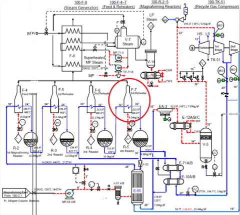
The reforming unit (Unit 100M) is a catalytic reforming process that utilizes four reactor beds with an ascending reactor inlet temperature profile. The lead reactors contain less catalyst and require less hydrogen to promote the dehydrogenation of naphtha to aromatics, while the lag reactors contain more catalyst and require higher hydrogen content to limit catalyst coking rates. Naphtha is fed to the unit from a naphtha hydrotreater stripper, passing through filters and a combined feed exchanger before entering the feed heater. The reactor effluent then flows through multiple re-heaters, where the temperature is raised to the desired inlet temperature for each reactor. This process aims to achieve a target aromatic content, or octane number, in the reformate stream [16]. The process flow diagram for reforming unit U100, refinery of Skikda [17] is represented in Figure 1.
The heater is designed to operate at a pressure of 16.6 bar and a temperature of 566℃; these conditions are known as the design pressure and design temperature. However, during operation, the actual pressure and temperature may vary. The operating pressure is 10.08 bar, and the operating temperature is 537.6℃. The heater is designed with a corrosion thickness of 1.6 mm, which means the material used in the construction of the heater is thick enough to withstand corrosion. This feature helps to maintain the integrity of the heater and prolongs its service life. The heater has 54 passes, which refers to the number of times the fluid (preheated naphtha) flows through the heater tubes.
As the reformer, tubes are usually used in harsh environments of high pressure and temperature, heat-resistant alloys with good mechanical properties and corrosion resistance are required. Based on these considerations, materials of high standards and special requirements have been selected for tube manufacturing [13].
The heater tubes are made of seamless ferritic alloy-steel A335 Grade P22, intended for high-temperature service. Its chemical composition is given in Table 1, which is provided by the ASTM designation A335/A335M-19, the standard specification for seamless ferritic alloy steel pipes for high-temperature service.
Table 1 aids in assessing the EDS results against the standard specifications outlined by ASTM. This comparison verifies any deviations between the actual chemical composition revealed by EDS and the typical composition expected according to ASTM standards, ensuring that the elemental composition of the material adheres to the prescribed values.
Table 1. Chemical composition of the heater tubes [18]
|
Grade |
UNS Designation |
|
Composition % |
|
P 22 |
K21590 |
Carbon |
0.05-0.15 |
|
Manganese |
0.30-0.60 |
||
|
Phosphorus |
025 max |
||
|
Sulfur |
0.025 max |
||
|
Silicon |
0.50 max |
||
|
Chromium |
1.90-2.60 |
||
|
Molybdenum |
0.87-1.13 |
The tubes have a diameter of 4 inches and a thickness corresponding to Schedule 40. The information regarding the tube material and the operating conditions of the heater is provided in Table 2.
Those process parameters enable us to assess the suitability of the chosen material (seamless ferritic alloy-steel A335 grade P22) for these operating conditions. It can be stated that the material selection was ideal for withstanding high temperatures and offering good resistance to corrosion and creep.
Figure 1. Process flow diagram of the reforming unit
Table 2. Tube material and heater operating conditions of the heater [19]
|
Equipment |
Type |
Service |
T(°C) |
P (kg/cm2) |
Tube Material |
|
Fired heater |
Box |
Heating (H2+HC vapor) |
Operation 537.6 |
Operation 10.08 |
4’’xA335/P22x/ Sch 40 (6.02AW) |
|
Design 566 |
Design 16.6 |
The casing of the heater is made of carbon steel, which is a common material used in the construction of heat exchangers and industrial equipment. Carbon steel is known for its strength, durability, and resistance to corrosion. This material is suitable for high-temperature and high-pressure applications.
Overall, the reformer heater is reliable and efficient industrial heating equipment that is designed to meet the demanding conditions of various process applications.
This study examines the degradation and life prediction of engineering equipment in a reforming plant, specifically focusing on catalytic reformer heater tubes. The equipment operates in a complex environment involving high temperatures, pressure, and a corrosive atmosphere, which can lead to degradation over time.
To conduct this study, several inspection techniques have been implemented: visual inspection, energy dispersive spectrometer (EDS) analysis was used to characterize the microstructure and chemical composition of the scale fragment samples taken from the tubes, metallographic examination was implemented using replica testing, hardness testing was used to evaluate the mechanical strength of the tubes, and the and the outer diameter of the tubes was measured to calculate the bulging rate [20].
There are a variety of inspection or testing methods for heater tubes. In assessing the state of furnace tubes, we have used an optimal combination of methods, as individual methods cannot detect any potential damage.
Visual inspection forms the initial stage, allowing for direct observation of the tubes' external condition. Furthermore, energy dispersive spectrometer (EDS) analysis was used to characterize the microstructure and chemical composition of the scale fragment samples extracted from the tubes.
Figure 2. Methodology steps
In addition to visual and chemical analysis, metallographic examination has been conducted through replica testing to identify any signs of degradation, such as cracks or structural changes. Furthermore, the tubes have been subjected to hardness testing to assess their mechanical strength and the material's resistance to deformation and ability to withstand mechanical stresses during operational conditions.
To complement these analytical techniques, measurements of the outer diameter of the tubes have been taken to calculate the bulging rate, revealing potential structural weaknesses or deformations in the tubes' geometry.
The methodology steps are summarized in Figure 2.
2.1 Visual inspection
One of the most basic forms of corrosion inspection is visual inspection. This method involves using the naked eye to look for signs of corrosion, such as discoloration, rust, or pitting on the metal surface. Visual inspection is a simple and inexpensive method that can be used to identify surface corrosion, but it may not be able to detect corrosion that is hidden beneath a coating or in a crevice.
2.2 Energy dispersive X-ray spectroscopy
As one of the most widely used analytical methods for the elemental composition analysis of solid matter, energy dispersive X-ray spectroscopy (EDS) has recently gained significant importance regarding its application to the chemical analysis of nanoparticles [21]. The method relies on the generation of characteristic X-rays that reveal the identity of the elements present in the sample [22].
Typically, this technique is used in conjunction with scanning electron microscopy [23]. The X-ray emissions from the prepared nanoparticles at different wavelengths are measured by a photon energy-sensitive detector. These X-rays are characteristic of each element and allow the determination of the nanoparticle elemental composition [24].
2.3 Replica test
Another method of corrosion inspection is the replica test and carburization of the outer surface. This method involves taking a replica of the metal surface and then analyzing it to identify signs of corrosion. The replica is made by applying a thin layer of plastic or other material to the metal surface and then peeling it off. This method can be used to detect corrosion that is not visible to the naked eye, such as pitting or crevice corrosion. It is a non-destructive sampling procedure that records and preserves the topography of a metallographic specimen as a negative relief on a plastic film [25].
The replica test is one of the methods used to evaluate degradation (residual life). It is a method that evaluates the possible damage initiation and its degree, which may not be detected by the non-destructive method. Thus, the method described in ASTM (Designation E 1351-01) evaluates the degradation of the facility and its remaining macro-residual life, as well as the damage initiation causes.
In degradation evaluation by the replica method, the overall evaluation is performed based on the changes in the microstructure and the damage state obtained from the microstructure replica of the objective surface. The degradation is divided into levels (Grade A~F). They are described in Table 3.
Table 3. Evaluation of a degree of degradation
|
Grade |
Condition |
Residual Life |
Condition |
|
A |
Early stage |
100% |
Recheck after 5 years |
|
B |
Progress step between A and C |
80% |
Recheck after 3 years |
|
C |
Intergrade |
60% |
Recheck after 2 years |
|
D |
Progress step between C and E |
40% |
Recheck after 2 years |
|
E |
The last period |
20% |
Recheck in a year Decision repair or replacement time |
|
F |
Destruction |
0% |
Immediately repair or replacement |
In our study, we have applied the replica test to two radiant tubes, A-37 and B-37.
2.4 Hardness test and wall thickness measurements
Hardness testing and wall thickness measurement are other methods of evaluating the metal surface condition. Hardness testing involves measuring the metal resistance to indentation and can be used to determine the mechanical strength of the metal, while wall thickness measurement involves using a micrometer or other tool to measure the thickness of the metal wall and can be used to detect corrosion that is causing the metal to be too thin.
2.5 Outer diameter measurement
The outer diameter measurement is a corrosion inspection technique that allows us to calculate the bulging rate and detect any changes in the heater tube diameter. A decrease in diameter indicates a sign of corrosion and possible pipe weakening.
3.1 Visual inspection
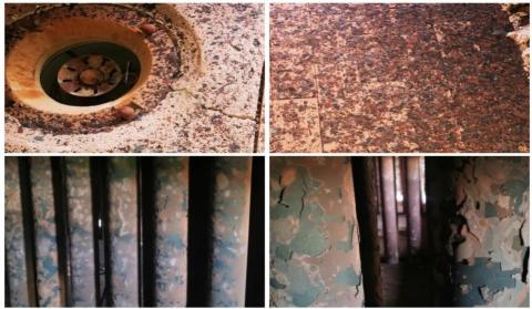
Visual inspection revealed that the radiant heater tubes have severe scale layers and are fragmented by thermal oxidation. It is illustrated in the photograph in Figure 3, taken from different areas of the fired heater.
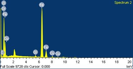
3.2 Energy dispersive X-ray spectroscopy (EDS)
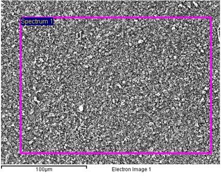
The Figure 4 represents the dark-scale fragment samples that have been taken from reforming unit heater tubes at the Skikda refinery in Algeria. Sample A corresponds to the outer surface of the scale, while sample B corresponds to the inner surface of the scale.
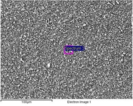
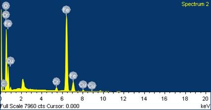
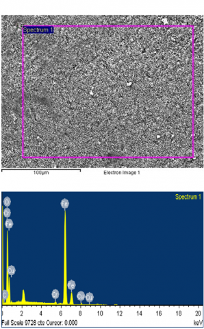
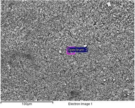
An energy-dispersive X-ray spectrum representative of the sample material is shown in Figures 5, 6, 7, and 8.
Figure 3. Inspected radiant tubes
Figure 4. Dark scale fragment samples taken from the heater tubes
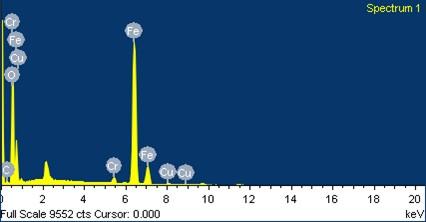
Figure 5. Energy dispersive spectrometer results from sample A of spectrum 1
Figure 6. Energy dispersive spectrometer results from sample A of spectrum 2
Figure 7. Energy dispersive spectrometer results from sample B of spectrum 1
Table 4. Chemical composition of samples A of spectrum 1
|
Spectrum Element |
Spectrum 1 |
|
|
Weight% |
Atomic% |
|
|
C |
2.64 |
6.83 |
|
O |
28.07 |
54.57 |
|
Cr |
1.72 |
1.03 |
|
Fe |
66.54 |
37.06 |
|
Cu |
1.04 |
0.51 |
|
Totals |
100 |
|
Figure 8. Energy dispersive spectrometer results from sample B of spectrum 2
The Tables 4, 5, 6, and 7 illustrate the results of quantifying the spectral data (chemical composition of samples A and B).
Table 5. Chemical composition of samples A of spectrum 2
|
Spectrum Element |
Spectrum 2 |
|
|
Weight% |
Atomic% |
|
|
C |
2.78 |
7.16 |
|
O |
28.32 |
54.74 |
|
Cr |
1.56 |
0.93 |
|
Fe |
65.69 |
36.37 |
|
Cu |
1.64 |
0.80 |
|
Totals |
100 |
|
Table 6. Chemical composition of samples B of spectrum 1
|
Spectrum Element |
Spectrum 1 |
|
|
Weight% |
Atomic% |
|
|
C |
2.82 |
7.32 |
|
O |
27.68 |
53.95 |
|
Cr |
0.99 |
0.59 |
|
Fe |
66.87 |
37.33 |
|
Cu |
1.73 |
0.80 |
|
Totals |
100 |
|
Table 7. Chemical composition of samples B of spectrum 2
|
Spectrum Element |
Spectrum 2 |
|
|
Weight% |
Atomic% |
|
|
C |
2.44 |
6.34 |
|
O |
28.15 |
54.97 |
|
Cr |
0.91 |
0.55 |
|
Fe |
66.77 |
37.33 |
|
Cu |
1.63 |
0.85 |
|
Totals |
100 |
|
For the two samples (a) and (b), we observe that five (05) peaks correspond to the existing elements (C, O, Cr, Fe, and Cu), of which we notice the appearance of a peak with a high intensity, which refers to the main element (Fe), whose mass percentage is between 66.54% and 66.77%, which aligns with the expected composition for ferritic alloy steel.
The second element in the quality of importance in mass percentage is oxygen (O), whose values revolve around 28, with a slight difference between sample (a) and sample (b) and between the same sample spectra. Oxygen is not explicitly listed in the ASTM Grade composition; its presence in the EDS analysis likely originates from the oxide layer formed on the surface of the material.
The carbon content is higher than the range specified by ASTM in the area that corresponds to the spectrum of the sample (a), with a value of 2.64 in mass percentage and lower values in the other spectra, suggesting potential contamination or variations in carbon content due to factors such as processing conditions or environmental exposure.
The EDS results indicate lower percentages of chromium and copper compared to the ASTM standard (about 1%). This could suggest variations in the alloying elements' distribution within the material or potential surface contamination.
3.3 Replica test and carburization of outer surface as per ASTM E 1351
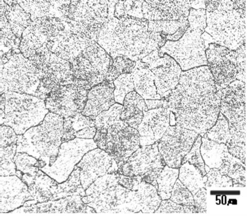
Microstructures showing the degradation degree and carburization of the heater are represented in Figures 9 and 10.
Figure 9. Microstructure of the tube A-37
Figure 10. Replica test results of the tube B-37
Transformed large spheroidal Fe3C carbide participates are observed in the above microstructure. Fe3C carbides in grain boundaries are coarsened. The degradation degree of tube A-37 is evaluated as being in grade D. We can observe that there is no detection of creep cavities, micro-cracks, inclusion, or segregation. The tube is not carburized.
The above microstructure shows structures mixed of ferrite and pearlite phases. Fe3C carbides decomposed into small particles and precipitated in grain boundaries. The degradation degree of tube B-37 is evaluated to be in grade C. There is no detection of creep cavities, micro-cracks, inclusion, or segregation. The tube is not carbonized. We can conclude that the radiant heater tubes are not carburized. The degradation degree is in grades C and D. The residual life is 40~60%.
3.4 Hardness test and wall thickness measurements
The hardness and wall thickness measurement results are represented in Table 8.
Based on the previous inspection data provided, the thickness measurements of the heater tube in the previous three years are, respectively, 4.72 mm, 4.70 mm, and 4.69 mm. The heater tube has a thickness of around 4.70 mm. A slight decrease in thickness is observed.
The hardness measurement values of the tubes from the previous three years are, respectively, 113 HB, 117 HB, and 124 HB. By comparing these results with the limit value provided by ASTM (171HB), it is concluded that the tubes still meet the specifications of the standard.
According to the obtained results, the hardness values of the heater tubes meet the specifications. The present wall thickness, considering the corrosion rate of 0.01~0.06 mm/year and the corrosion allowance of 1.6 mm, according to 30 years’ operation, is safe.
Table 8. Hardness and wall thickness measurement test results
|
Tube No. |
Wall Thickness (mm) (Design Ave. 6.02) |
Hardness (HB.) (ASTM A335 Gr. P22 Spec.171 HB.) |
|
A-8 |
5.04 |
143 |
|
A-17 |
5.46 |
128 |
|
A-26 |
4.44 |
123 |
|
A-35 |
4.72 |
137 |
|
A-37 |
5.38 |
126 |
|
A-43 |
5.05 |
126 |
|
A-50 |
4.20 |
130 |
|
B-8 |
4.70 |
122 |
|
B-17 |
4.18 |
131 |
|
B-26 |
4.89 |
124 |
|
B-35 |
4.97 |
131 |
|
B-37 |
4.09 |
109 |
|
B-43 |
4.36 |
123 |
|
B-50 |
4.24 |
124 |
|
Average |
4.69 |
127 HB. |
3.5 Outer diameter
The results of the measured outer diameter and calculated deformation rate are represented in Table 9.
Bulged tubes were not observed in the visual inspection, and after measuring the outer diameter, the deformation rate (bulging rate) satisfied the measuring error within ±1% as well. Therefore, the outer diameter of the heater tubes in each item is normal. It is assumed that creep cavities start forming when the deformation rate (bulging rate) exceeds 2.0%.
Table 9. Outer diameter results of the heater tube
|
Location |
Results |
||||
|
Tube No. |
Replica No. |
0° (mm) |
Deformation Rate (Bulging Rate), % |
90° (mm) |
Deformation Rate (Bulging Rate), % |
|
A 37 |
R14 |
113.3 |
-0.87 |
112.65 |
-1.44 |
|
B 37 |
R15 |
112.7 |
-1.40 |
113.00 |
-1.14 |
There are various inspection and testing methods available for assessing the condition of heater tubes. However, it's important to recognize that each technique used has its limitations and may not be able to detect all forms of damage effectively. By solely relying on one technique, we risk overlooking certain types of damage or issues. Therefore, to ensure a comprehensive evaluation of furnace tubes, we have adopted an optimized combination of methods. This approach allows us to overcome the limitations of individual techniques and obtain more accurate and thorough results.
After analysis, energy dispersive X-ray spectroscopy revealed the presence of copper, indicating its penetration during combustion and pointing to pure thermal oxidation. Additionally, the results of the replica test have shown that the heater tubes are not carbonized, and no signs of creep have been observed. The mechanical properties were evaluated through hardness and wall thickness measurements, confirming that the values met the required specifications. Moreover, these findings provided no indication of carburization or metal dusting. No bulged tubes were detected during the visual inspection.
Moreover, upon measuring the outer diameter, it was found that the deformation rate (bulging rate) falls within the acceptable margin. Consequently, the outer diameter of the heater tubes in each instance appears to be within normal parameters. This indicates that there are no indications of creep occurring.
The results of this study indicate that the radiant heater tubes are damaged by thermal oxidation. Experimental results show that the tube was exposed to excessive temperatures, which led to corrosion of the external surface. The high temperature and the presence of excess oxygen in the atmosphere contributed to the oxidation of the tube, which extended over the entire length of the tube, and it can be accelerated by over-firing or internal fouling of the tubes. Under these conditions, oxide scale accumulates on the heater tubes, reducing their efficiency and increasing the risk of tube failure. The build-up of scale acts as an insulator, reducing heat transfer and increasing the surface temperature of the tubes, leading to reduced thermal efficiency.
Based on the results of the study, the suggested recommendations are provided in order of priority to prevent this type of damage:
By implementing these recommendations, it is possible to reduce the risk of thermal oxidation and prolong the lifespan of the heater tubes, ensuring safe and efficient heater operation and improving efficiency.
[1] Bonaccorsi, L., Guglielmino, E., Pino, R., Servetto, C., A., Sili, A. (2014). Damage analysis in Fe–Cr–Ni centrifugally cast alloy tubes for reforming furnaces. Engineering Failure Analysis, 3: 65-74. https://doi.org/10.1016/j.engfailanal.2013.09.020
[2] American Petroleum Institute. (2021). API Recommended Practice 573: Inspection of Fired Boilers and Heaters, 4thedition. https://store.accuristech.com/standards/api-rp-573?product_id=2204992.
[3] American Petroleum Institute. (2020). API recommended practice 571: Damage mechanisms affecting fixed equipment in the refining industry, 3rd edition. https://inspectioneering.com/tag/api+rp+571.
[4] Ghasemi, H. (2011) High-temperature sulfidation of carbon steel heater tubes in gas condensate containing sulfur compounds. Engineering Failure Analysis, 18(3): 980-998. https://doi.org/10.1016/j.engfailanal.2010.11.017
[5] Ray, A.K., Roy, N., Raj, A., Roy, B.N. (2016). Structural integrity of service exposed primary reformer tube in petrochemical industry. International Journal of Pressure Vessels and Piping, 137: 46-57. https://doi.org/10.1016/j.ijpvp.2015.10.003
[6] American Petroleum Institute. (2016). API recommended practice 570: Inspection practices for piping system components, 4th edition. https://www.academia.edu/93214191/API_570_Piping_Inspection_Code_In_service_Inspec_2016?uc-g-sw=8136590.
[7] American Petroleum Institute. (2016). API recommended practice 580: Risk-based Inspection, 3rd ed, American Petroleum Institute.
[8] American Society of Mechanical Engineers. ASME PCC-3 – 2017: Inspection planning using risk-based methods, December 2017. https://www.scribd.com/doc/278126818/99186464-ASME-PCC-3-2007-Inspection-Planning-Using-Risk-Based-Methods.
[9] Naubnome, V., Haryadi, G., Ismail, R., Kim, S. (2016). Rısk analysis for pressure vessel with external corrosion using RBI method based on API. AIP Conference Proceedings, 1725: 020052. https://doi.org/10.1063/1.4945506
[10] Tien, S.W., Hwang, W.T., Tsai, C.H. (2007). Study of a risk-based piping inspection guideline system. ISA Transactions, 46(1): 119-126. https://doi.org/10.1016/j.isatra.2006.06.006
[11] Khan, FI., Haddara, M.M. (2003). Risk-based maintenance (RBM): A quantitative approach for maintenance/inspection scheduling and planning. Journal of Loss Prevention in the Process Industries, 16(6): 561-573. https://doi.org/10.1016/j.jlp.2003.08.011
[12] American Petroleum Institute, American society of mechanical engineers, API 579-1/ASME FFS-1 2021: Fitness-for-service, 2021 edition. https://www.asme.org/codes-standards/find-codes-standards/ffs-1-fitness-service/2021/drm-enabled-pdf.
[13] Shi, J., Han, Z.Y., Zhuang, F.K., Xu, M., Xie, G.S., Tu, S.T., Wang, W.Z. (2021). Failure analysis of high-temperature reformer tube of Incoloy 800H in synthetic ammonia installation. Engineering Failure Analysis, 121: 105122. https://doi.org/10.1016/j.engfailanal.2020.105122
[14] Ray, A., Goswami, B., Kumar, S.B., Krishna, G., Roy, N., Ray, A.K. (2015). Damage mechanism of service exposed reformer tubes in petrochemical industries. International Journal of Engineering and Technical Research, 33(3): 454-4698. https://doi.org/10.1515/htmp-2013-0040
[15] Shalaby, H.M., Ravindranath, K., Tanoli, N., Al-Wakaan, B. (2017). Failure of 321 stainless steel heater tube in heavy crude oil. Case Studies in Engineering Failure Analysis, 9: 1-8. https://doi.org/10.1016/j.csefa.2017.04.004
[16] Park, K., Choi, P., Shin, H. (2013). Operating manual of reforming unit U100. Refinery of Skikda, 1-7. https://www.scribd.com/document/470349106/Manuel-operatoire-U100-OK-pdf.
[17] Park, K., Choi, P., Koh, C. (2011). Process flow diagram for reforming unit U100. Refinery of Skikda, 1-14.
[18] American Society for Testing and Materials. (2019) Standard Specification for Seamless Ferritic Alloy-Steel Pipe for High Temperature Service, Designation: A335/A335M – 19.
[19] Park, K., Choi, P., Shin, H., Koh, C. (2013). Process datasheet for feed heater, 1st/2nd/3rd re-heater, steam generator, item no: 100-f-4/5/6/7/8, U100 refinery of Skikda, 3-7.
[20] IštvanKucora, I., Radovanović, L. (2014). Pyrolysis furnace tube damaging and inspection. ACTA TEHNICA CORVINIENSIS – Bulletin of Engineering Tome, Fascicule 3, 2014.
[21] Hodoroaba, V.D. (2019). Chapter 4.4 - Energy-dispersive X-ray spectroscopy (EDS). Characterization of Nanoparticles, 397-417. https://doi.org/10.1016/B978-0-12-814182-3.00021-3
[22] Scimeca, M., Bischetti, S., Lamsira, H.K., Bonfiglio, R., Bonanno, E. (2018). Energy dispersive X-ray (EDX) microanalysis: A powerful tool in biomedical research and diagnosis. European Journal of Histochemistry, 62(1): 89-99. https://doi.org/10.4081/ejh.2018.2841
[23] Rades, S., Hodoroaba, V.D., Salge, T., Wirth, T., Lobera, M.P., Labrador, R.H., Natte, K., Behnke, T., Gross, T., Unger, W.E.S. (2014). High-resolution imaging with SEM/T-SEM, EDX, and SAM as a combined methodical approach for morphological and elemental analyses of single engineered nanoparticles. RSC Advances, 4: 49577-49587. https://doi.org/10.1039/c4ra05092d
[24] Hodoroaba, V.D., Rades, S., Unger, W.E.S. (2014). Inspection of morphology and elemental imaging of single nanoparticles by high-resolution SEM/EDX in transmission mode. Surface and Interface Analysis, 46(10-11): 945-948. https://doi.org/10.1002/sia.5426
[25] American Society for Testing and Materials. (2001) Standard practice for production and evaluation of field metallographic replicas, designation E 1351 – 01, vol 1. https://www.scribd.com/document/368846316/E1351.